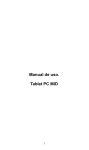
1
USER MANUAL microADSB-IP receiver v.4 =BULLION= www.microADSB.com JAN 2014 -0- Table of Contents What is New in version 4. .................................................................................................. - 2 About microADSB-IP receiver ........................................................................................... - 2 1 Terms Of Use: .................................................................................................................... - 3 2 Introduction ...................................................................................................................... - 3 3 Antenna .............................................................................................................................. - 4 4 Microadsb-Receiver ....................................................................................................... - 4 5 adsbPIC-Decoder ........................................................................................................... - 4 6 TCP/IP converter ............................................................................................................... - 4 7 Installation .......................................................................................................................... - 5 7.1 Connecting the Hardware..................................................................................... - 7 - 7.2 Configuring Your Computer ................................................................................. - 7 - 7.3 Configuration Tool ................................................................................................... - 10 7.3.1 Network Configuration ....................................................................................... - 11 7.3.2 Serial Configuration ............................................................................................ - 15 7.3.3 Option Configuration........................................................................................... - 16 8 PC-Software .................................................................................................................... - 17 8.1 ADSBscope ............................................................................................................ - 17 8.1.1 Installation ......................................................................................................... - 17 8.1.2 Start the Software .......................................................................................... - 17 8.1.3 Connect ADSBscope to receiver BULLION.................................................. - 19 8.1.4 RAW data Client ............................................................................................... - 20 - 8.1.5 Server (decoded data) ................................................................................ - 20 8.2 Planeplotter ........................................................................................................... - 21 9 Glossary .......................................................................................................................... - 23 10 Schemes ..................................................................................................................... - 24 - -1- What is New in version 4. New metal box with very good seal (IP65) with through holes for mounting. New IP controller, high speed 100MB/s, messages with greater intensity and minimum errors. Special tool to adjust the network part using MAC address. Replacing the switching regulators of supply with parametric regulator in order to reduce noise at the receiver. PoE supply voltage limited 7-9V, DC. Antenna connector is soldered directly to the board. Ability to work in USB connection mode and firmware upgrade. About microADSB-IP receiver Low cost IP receiver Affordable coverage & redundancy Up to 250 Nm range High accuracy independent of distance High Update rate Provides Identity of the aircraft Supports Cockpit Display of Traffic Information Cooperative Finally there is a quality virtual radar receiver at a price you can afford, substantially lower than other receivers on the market but with all the performance you need. The microADSB radar receives real time transmissions from commercial aircraft and through the ADSBScope or PlanePlotter software displays them on your PC, it is like having air traffic control in your living room! You can watch flights in your local area in real time within a practical range up to 250 Nm with typical 1st floor window sill antenna position, greater if you have an ideal antenna position. Identify those airliners you see flying over, and even watch them stacking at your local airport! Most large civil aircraft such as commercial airline flights carry equipment that transmits information over a system known as ADS-B. ADS-B contains information like the name of the flight, the ICAO number of the aircraft, the aircraft's current position, speed and direction, and how fast the aircraft is descending /acceding. This information is received by the microADSB receiver whit ADS BScope or PlanePlotter software decodes this placing the aircraft on a ma p of your local area. -2- 1 Terms Of Use: We present to your attention/some open-sources connected with this project from our point of view. Our developer’s experience has been gained from the links listed below or similar: http://www.sprut.de/electronic/pic/projekte/adsb/adsb.htm http://www.mikrocontroller.net/articles/1090_MHz-ADS-B-Receiver http://miniadsb.web99.de/ http://www.coaa.co.uk/planeplotter.htm http://www.microADSB.com http://www.anteni.net 2 Introduction This User Manual is based on: Decoder adsbPIC hardware - version 4, firmware 14 An ADS-B-receive system can be used as virtual radar to generate a live picture of the air traffic. It is build up from 5 main stages: Antenna Receiver Decoder Network (TCP/IP & UDP) interface PC-software Fig.1: ADS-B receiver 1.The antenna has to receive the 1090 MHz radiation and to convert it into an electric UHF-signal. 2.The receiver selects, amplifies and demodulates the received signals and generates an analog signal. 3.The decoder converts analog into digital and detects ADS-B transmissions inside digital signal. The ADS-B signals are then forwarded to a PC via: 4.ETERNET connection. 5.The PC decodes the ADS-B information and generate the virtual radar display. It may support the exchange of ADSB-data via the internet. This handbook is mainly focused on the microADSB-IP and the PC-software ADSBScope or PlanePloter, run under WINDOWS OS. -3- 3 Antenna For better performance antenna with vertical polarization, 50 Ohms impedance, tuned to 1090 MHz has to be used. We offer model MS10905 (http://microadsb.com) 5db gain which is included in Option 3 of the BULLION microADSB-IP receiver. The antenna has to be placed as high as possible at a location with a good ”view” into all directions. The antenna input is N connector. 4 Microadsb-Receiver The microadsb is a small and simple direct detection receiver for 1090 MHz. 5 adsbPIC-Decoder The decoder converts the analog signal (from the receiver) into a digital signal, detects the ADS-B-frames in the signal, and sends them to the PC. Fig.2: Decoder block- d iagram The heart piece of the adsbPIC-decoder is a PIC18F2550 microcontroller. It converts the analog signal into a digital signal by use of an internal comparator. Then it tries to detect ADS-B messages inside the digital signal. The received ADS-B messages are then transferred by serial interface to the TCP/IP & UDP converter in the Ethernet controller. 6 TCP/IP converter Represents the converter from serial interface to TCP/IP. It is built based on WIZ108SR modul. Converts a serial interface to Ethernet 100mb/s. Fig.3: TCP/IP converter -4- For more information, visit the website at http://www.wiznet.co.kr Attention! Ethernet output is not automatically crossover-ed. 7 Installation At the receiver is mounted N male coaxial connector for the antenna connection. For ETHERNET connection is mounted RJ45. Two pairs of cables carrying power supply PoE. Since the input is Bridge Rectifier, the polarity does not matter. Fig.4: View of microADSB-IP BULLION v.4 Power over Ethernet or PoE technology described as a system to pass electrical power safely, along with data, on Ethernet cabling. The IEEE standard for PoE requires Category 5E cable or higher for high power levels. Power is supplied in common mode over two of the differential pairs of wires found in the Ethernet cables and comes from a power supply within a PoE-enabled networking device such as an Ethernet can be injected into a cable run with a power supply. Fig.5: Power injector Passive Power over Ethernet: Pair 4,5 -one pole Pair 7,8 -return Polarity does not matter. Voltage is 7 to 9V DC. Current is about 300mA. By the 4-position switch on the PCB (Fig.5.1) several additional modes can be set: -5- Fig.5.1: Default mode of the 4-position switch 1 position ON - only the data from aircrafts with position is decoded and processed 2 position ON – add a time stamp to the RAW data massages 3 position ON (4 position OFF) - the receiver works in IP mode and sends data through Ethernet 4 position ON (3 position OFF) – the receiver works in USB mode (no data via Ethernet). With USB cable connected to the 4 pin connector (shown on schematics in Chapter 10) the receiver works just as microADSB-USB receiver. In this mode the firmware of the receiver can be updated. PC/Hub/Switch Standart Eternet Cable 8v DC max100m Injector Fig.6: Connecting the microADS-IP BULLION receiver -6- 7.1 Connecting the Hardware Shut down your PC and any other equipment before connecting it to the receiver. To connect your receiver: 1. Verify that the receiver’s power supply is in the Off. Verify that any PCs and other LAN devices you will attach (such as hubs or switches) are turned off. 2. Use the standard patch cable to connect the RJ45 of the receiver 3. Use the Power injector to connect your computer to the other side of cable. Either a crossover or a straight-through ethernet cable can be used: the router determines the type of signal required. 4. Connect the cylindrical power plug into the POWER connector. Plug the AC/DC adapter (Not supplied in the box) into a wall outlet or a power strip. We recommend 7-9V DC, at least 350mA. 5. Turn on your PC and any other LAN devices, such as hubs or switches. 6. Turn on the receiver. 7. Verify that the some of receiver's LEDs are illuminating. 7.2 Configuring Your Computer Before you can access the receiver over the LAN you have to configure your PC's TCP/IP address to be 192.168.1.x (where x is any number between 12 and 254), with a subnet mask of 255.255.255.0. Your receiver's default IP address is 192.168.1.11. If you know the version of Windows that you use, go to the appropriate section below to learn how to set the IP address of your PC. To determine the version of Windows running on your PC, click on the Windows Start button, then click on Run... in the Start menu. Type winver in the Open selection box and click on OK. Fig.7: Windows Run Dialog The Windows version is displayed. -7- Fig.8: Windows Version Windows XP 1. In the Windows task bar, click on the Start button, and then click on Settings, Network Connections. Fig.9: Path to Network Connection 2. Double-click on the Network Connections icon. 3. In the LAN or High-Speed Internet window, right-click on the icon corresponding to your network interface card (NIC), and select Properties. (Often this icon is labeled Local Area Connection). The Local Area Connection dialog box displays with a list of currently installed network items. 4. Ensure that the check box to the left of the item labeled Internet Protocol (TCP/IP) is checked, and click on Properties. -8- Fig.10: Network Connections (Windows XP) Fig.11: Local Area Connection Properties (Windows XP) 5. In the Internet Protocol (TCP/IP) Properties dialog box, click on the radio button labeled Use the following IP address. Type an address between 192.168.1.12 and 192.168.1.254 in the IP Address field (192.168.1.20 is shown here as an example) and 255.255.255.0 in the Subnet Mask field. -9- Fig.12: TCP/IP Properties (Windows XP) 6. Click on OK twice to confirm your changes, and close the Control Panel. 7. To check the connection between the computer and the receiver use the ping command. In the Windows task bar, click on the Start button, and then click put cmd command. Then in the window, type the command ping 192.168.1.11 Fig.13 Command Prompt The responses show that there is a connection between the two devices. 7.3 Configuration Tool As previously mentioned the IP address of microADSB-IP BULLION receiver by default is 192.168.1.11. To lower the probability to match your home or internet network we recommend to change network parameters by special program called - 10 - Configuration Tool from the Resource CD: For Installation, start setup.exe This will install the program to: "C:\Program Files (x86)\WIZnet\Configuration Tool (ver 1.4.4.0)\" 7.3.1 Network Configuration. Fig.14: WIZ108SR Configuration Tool (Network Configuration Page) 1) Search The Search function is used to search all devices existing in the same LAN or in WAN. By using UDP broadcast as shown in Fig.15, all connected devices in the same subnet will be found. If the TCP unicast method is checked, the specified IP address must be given as shown on Fig.16. The founded device will be listed in the “Serial to Ethernet” tree with its MAC address. Please, note that the identification code must be input if the device has been configured with one identification code. - 11 - Fig.15: Searching with UDP broadcast method Fig.16: Searching with TCP unicast method 2) Setting This function is to complete the configuration change. If you select the MAC Address from the “Serial to Ethernet” tree, the default configuration value of the module will be displayed. Change the configuration and click “Setting” button to complete the configuration. The module will re-initialize with the changed configuration. Changed value is saved in the EEPROM of the module. Thus, the value is not removed even though power is disconnected. 3) Upload Firmware will be uploaded through network (only network controller firmware) Programing of the receiver is made using USB connection only 4) Reset Reset and restart the selected module if you select the MAC Address from the tree and click “Reset” button. 5) Factory All value is initialized to Factory default value if you select the MAC Address from the tree and click “Factory” button. 6) Ping Popup the Simple Ping application program, you can test the ping operation. - 12 - Fig.17: Simple Ping Test Program 7) Firewall Popup the Windows Firewall setup program. 8) Exit Close the configuration Tool Program. 9) Search window If you click “Search” button, all the MAC address on a same subnet, will be displayed this area. You can see the basic information such as Model name, Firmware version Etc. 10) Network Setting Method Select IP setting mode, you can select one of Static, DHCP. (PPPoE mode is not supported in the WIZ108SR) - Using the follow IP Address (Static) This is option for setting ETHERNET MODUL module’s IP with static IP address. Firstly, select MAC address which you wanted to set as static IP in the board list. Then “Device IP, Subnet, Gateway box” will be enabled. Input Static IP address and click “setting” button. Then set the IP address as you want. - DHCP Set this option to use DHCP mode. Firstly, check ‘DHCP’ and click ‘Setting’ button. If IP address is successfully acquired from DHCP server, the MAC address will be displayed on the configuration window. (It takes some time to acquire IP address from DHCP server) When a module on the board list is selected, IP address, Subnet mask and Gateway are displayed. If module could not acquire network information from DHCP server, IP address, Gateway Address and Subnet mask will be initialized to 0.0.0.0. 11) Network Operation Mode Client / server / mixed: This is to select the communication method based on TCP. TCP is the protocol to establish the connection before data communication, but UDP just processes the data communication without connection establishment. The Network mode of ETHERNET MODUL can be divided into TCP Server, TCP Client and Mixed mode according to the connection establishing method. At the TCP server mode, ETHERNET MODUL operates as server on the process of connection, and waits for - 13 - the connection trial from the client. ETHERNET MODUL operates as client at the TCP Client mode on the process of connection, and tries to connect to the server’s IP and Port. Mixed modes supports both of Server and Client. The communication process of each mode is as below. <TCP server mode Communication> At the TCP Server mode, ETHERNET MODUL waits for the connection requests. TCP Server mode can be useful when the monitoring center tries to connect to the device (where ETHERNET MODUL is installed) in order to check the status or provide the commands. In normal time ETHERNET MODUL is on the waiting status, and if there is any connection request (SYN) from the monitoring center, the connection is established (ESTABLISH), and data communication is processed (Data Transaction). Finally connection is closed (FIN). In order to operate this mode, Local IP, Subnet, Gateway Address and Local Port Number should be configured first. The Data transmission proceeds as follows, 1. The host connects to the ETHERNET MODUL which is configured as TCP Server mode. 2. As the connection is established, data can be transmitted in both directions – from the host to the ETH ERNET MODUL, and from the ETHERNET MODUL to the host <TCP client mode Communication> If ETHERNET MODUL is set as TCP Client, it tries to establish connection to the server. To operate this mode, Local IP, Subnet, Gateway Address, Server IP, and Server port number should be set. If server IP had domain name, use DNS function. In TCP Client mode, ETHERNET MODUL can actively establish a TCP connection to a host computer when power is supplied. The Data transmission proceeds as follows: 1. As power is supplied, ETHERNET MODUL board operating as TCP client mode actively establishes a connection to the server. 2. If the connection is complete, data can be transmitted in both directions – from the host to the ETHERNET MODUL and from ETHERNET MODUL to the host <Mixed mode Communication> In this mode, ETHERNET MODUL normally operates as TCP Server and waits for the connection request from the peer. However, if ETHERNET MODUL receives data from the serial device before connection is established, it changes to the client mode and sends the data to the server IP. Therefore, at the mixed mode, the server mode is operated prior to the client mode. As like TCP Server mode, the Mixed mode is useful for the case that the monitoring center tries to connect to the serial device (in which ETHERNET MODUL is used) to check device status. In addition to this, if any emergency occurs in the serial device, the module will change to Client mode to establish the connection to the server and deliver the emergency status of the device. <Use UDP mode> UDP is not a connection oriented protocol. But the communication port should also be defined well. If the UDP mode is selected, the data from serial interface can be defined where to delivery via the “Sever IP Address” and “Port”, and the ETHERNET MODUL can also be defined where to receive Ethernet data from via the “Remote Peer IP Address” definition. If the data - 14 - destination and source are the same, the two IP address will also be the same. Please note the destination and source are using the same port. 12) DDNS Setting DDNS function is not supported in the ETHERNET MODUL. 7.3.2 Serial Configuration. The serial settings used by BULLION are shown on the Fig.18. These settings should not be changed. If you have command Factory these settings must be reentered again manually. Fig.18: Default serial settings of BULLION ☞ By clicking the “Setting” button, changed value can be applied. - 15 - 7.3.3 Option Configuration Fig.19: ETHERNET MODUL Configuration Tool (Option Configuration Page) 1) Timer interval - Inactivity Timer: The connection holding period when no data transmission. - Reconnection Interval: The connection retry interval (client mode only) When the connection is established, if there is not data transmission within the time defined in Inactivity time, the connection is closed automatically. The default value is ‘0’. If ‘0’ is set, this function is not activated. In this default setting, the connection is maintained even though there is no data transmission. In order to close the connection, the ‘Close’ command should be given. This function can be used for more than two or more systems to connect to the ETHERNET MODUL. If one system holds the connection to the ETHERNET MODUL, other systems cannot connect to the module. If there is no data transmission during the time defined in Inactivity time, the connection will be closed for other system to be connected. Inactivity Time also can be useful for the case when the server system is unexpectedly shut down. In this status, if there is not any data communication during the time defined in the - 16 - Inactivity time, ETHERNET MODUL will close the connection and enter into waiting status. 2) Search identification code For the security issues, ETHERNET MODUL can have its own password for searching. The password is stored in the EEPROM of ETHERNET MODUL, and it can be modified via this configuration tool. The password can be any alphabet or number. Its length can be variable and its maximum length is 8 bytes. The password is case sensitive. 3) Connection password This function is available only when ETHERNET MODUL works in server mode. If this function is enabled, the remote client should send the password to ETHERNET MODUL before data transmission. Please, note the password is case sensitive. 4) Network protocol settings.There are two kinds of data transmission protocol: one is raw data transmission, and the other is using Telnet (RFC2217). But in current version, only the raw data transmission is supported. If the ‘Keep alive’ function is enabled, ETHERNET MODUL will send keep alive packet in every user set minutes if no reply received after the user set period. 8 PC-Software There is a variety of software applications that can use the data from the receiver and displays them (AVR format). Here we will explain how to get the receiver to work with two of the most popular programs: ADSBScope and PlanePlotter. 8.1 ADSBscope The software AdsbScope is exchange data via LAN or internet. AdsbScope is a Win32-application. It is developed and tested under Windows-XP and Win7. To use it at Windows-Vista it may be necessary to use the compatibility mode of these operating systems. 8.1.1 Installation The software is part of the resource CD. Also you can download the latest version from: http://www.sprut.de/electronic/pic/projekte/adsb/adsb_fix.zip Create a directory and copy the software into this directory. 8.1.2 Start the Software To start the software double-click the executable file: adsbscope26f3_256.exe. AdsbScope will open its program window centered at the monitor, check out the subdirectories and load some data files. If a default program state was saved, then this will be loaded, and adsbScope will use the saved coordinates, zoom-value, window size and open street map background picture. - 17 - Fig.20: Program window The program window contains: a menu to control the program a graphic display a text box for raw data a text box for decoded data a table for detected aircraft a decoder control area an information field If no default program state is available, then it will use the starting position: 6 deg east 51 deg north (and no OSM picture) as start point. Use the mouse to move to your home destination or load a program state with the coordinates of your home. All incoming adsb-information is listed in the upper text box. Fig.21: Typical RAW data At high frame rates the RAW-data zips through this window toо fast for the human eye. A simple mouse click on the window interrupts the list of RAW-data. A second click activates the list of data again. If the box has collected more then 20000 lines, then it will be erased - 18 - to save memory space. The decoded content of the information is listed in the lower text box. If the box has collected more then 20000 lines, then it will be erased to save memory space. Fig.22: Typical decoded data Data of detected aircraft is shown in the table between both text boxes. The picture on the left side of the program window shows position, track history and additional information of aircraft with known position. The software counts the number of ADS-B frames (data packets) per minute and displays it in the lower right corner of the program window and in the program status bar. Behind this value is shown (in parenthesis) the average number of frames received from one aircraft per minute. 8.1.3 Connect ADSBscope to receiver BULLION The software can distribute decoded data and received raw data via network/internet. The default network settings can be changed via the Network window. (Menu: other - Network - network setting). Fig.23: Network setting Screen - 19 - Fig.24: Network setup 8.1.4 RAW data Client The software can receive raw decoder data via network. You can connect to an active RAW-data-server via the menu point other Network - RAW-data client active or by a click on the grey RAWdata Client button right of the server buttons. Of course you can choose any other RAW-data-server, e.g. receivers with adsbScope-Software. You can change the IPaddress and the port number of the used RAW-data-server via the network-setup. Connections to other RAW-data severs have no time limit. 8.1.5 Server (decoded data) The software contains a server at port 30003. Via this server the received and decoded information can be forwarded to multiple clients. The output format is (hopefully) compatible to RadarBox and SBSBasestation. However, We was not able to test this in details. To start the server one can click the left of the both gray networkserver-icons (right of the OSM icon). The server is started, a - 20 - comment is written in the upper log-window and the icon gets colors. Now clients can connect the server at port 30003. To deactivate the server just click on the icon again. To test the running server you can start your internet-browser on the same computer and type in http://localhost/30003/. This server is enabled when sending data to Flightradar24. Description of how it works can be found at: http://www.flightradar24.com/software 8.2 Planeplotter Since version 6.2.3.7x of the PlanePlotter is the possible inclusion of ADSB-IP receiver directly. You can download the latest version from: http://www.coaa.co.uk/planeplotter.htm To use the IP-receiver with Planeplotter as Mode-S-Receiver one hast to choose "AVR receiver TCP”. Fig.25: Login Screen - 21 - Fig.26: Login Screen Select the Mode-S receiver, the AVR receiver and Setup TCP client. Fig.27: Login Screen Enter the IP address and port of the receiver. Activate the processing of the software with a click on the button with the green circle. - 22 - 9 Glossary ADS-B Automatic Dependent Surveillance-Broadcast. This is a cooperative surveillance technique for air traffic control. An ADS-B-equipped aircraft determines its own position and periodically broadcasts this position and other relevant information to the potential ground stations and t o t h e other aircrafts with ADS-B in equipment. (http://en.wikipedia.org) AVR This is a family of microcontrollers. (also known as Atmelmicrocontrollers). Such microcontrollers are used in some decoders. Comparator It converts the analog video signal from the receiver into a digital video signal. Decoder Detects ADSB-data (frames) inside the digital video signal from the comparator and send it to the computer. DF This is the type of an ADS-B-frame. Frame ADSB-data is radiated in small packages. Such a package is called a frame. There are different types of frames radiated. The type is called DF (download format). The most valuable frame type is DF17, it contains aircraft coordinates. Frames contain 56 bits (DF0 ... DF15) or 112 bits (DF16 ... DF31) of information. Every aircraft radiates some hundred frames per minute. Normally every flying aircraft radiates two DF17-frames per second. Knots Knots is the common unit to measure speed in aeronautic and shipping. One knot is equal to one nautical mile per hour or 1.8 kilometers per hour. NM Nautical mile (NM) is the common unit to measure distances in aeronautic and shipping. One NM is equal to 1.8 kilometers. One nautical mile is the length of one longitude-minute at the equator. Consequently the circumference of the earth is 21600 NM (360 x 60). OSM OSM stands for open street map. It’s a free collaborative project to create detailed maps of the earth for free use. - 23 - PWM Pulse Width Modulation is used in my decoder to generate a reference voltage for the comparator. RAW-data This is the unprocessed data that the decoder delivers to the computer. Normally this is the received frame-data as textstrings. Receiver It converts the 1090 MHz-electric signal from the antenna into an analog video signal. TAG (timeTAG) Here: the precise time tags, which decoders can generate. It makes it possible to measure the time of arrival of every dataframe with a precision of fractions of microseconds. 10 Schemes - 24 - - 25 - 1 0k 1n 22 u USB 39 p TA1 090 EC 39 p 22n Ba 033 01 01 01 39 p TA 023 2A 2,2u 01 2,7p 2 ,7p 2 ,2 u зелен 10 1 0 01 1k 5 ,6 k 1n 01 AD8 31 3 1n син 4 ,7 k 01 1k 01 1k 1k 4 7k A DM4 88A RZ 2 2u -DF17- -TIME- -IP/USB- -USB_R- червен 22 u PIC 18 F2 550 22 p 22p 2 0MHz 470 n 4 ,7 u 4 7k 1 0k 4 ,7 u 4 ,7 u Programing DB1 06 S 78 M05 - 26 - - 27 - 1 2 3 4 micro ADSB-IPv4 receiver A A www.microADSB.com 1nF 100nF C4 C5 bead B1 2.2uF L1 82nH C20 B E C2 TA1090EC A C D 10k 4 F 1 SAW Filter U4 TA0232A 3 5 2 2 5 6 3 4 7 8 * C7 2.7pF C10 R4 10R C19 AD8313 1 GND D1 bead B2 R6 5.6K LL4148 GND R5 4.7K 4 2 L2 8,7nH C8 * GND GND GND C6 39pF 39pF R1 GND GND 1nF GND 1 BGM1013 6 U2 100nF R3 10R C9 100nF C21 7 GND U1 SAW Filter 39pF C1 2.2uF 8 U3 2.7pF 78M05 1 3 6 C3 22nF antenna 50om C22 100nF C12 100nF 5 1nF C11 GND R10 GND 20MHz Q1 OSC2 1 2 3 4 RA0 RA1 RA2 RA3 RB0 RB1 RB2 RB3 RB4 RB5 RB6 RB7 10 USB P? Vss GND GND +5v OSC1 100n 2 C 9 ADR-R D3 D4FRM-Y C13 47K Vin C26 C23 C27 4,7u 22u 0.1 Vout U9 GND 2 C18 22u C16 GND 2 3 4 5 21 22 23 24 25 R11 26 27 28 Remote rs232 Time DF17 C24 0.1 C14 22pF GND GND C15 22pF GND GND B G1 +5v 4 3 2 1 5 6 7 8 ADM488ARZ 1 U5 SW DIP-4 2 5 4 3 2 1 P1 programing 3,3v GND U7 8 5 6 3 PoE 1 2 GND 7 GND GND GND C28 22u 47k GND GND GND GND C25 4.7u C17 GND 470nF PIS4 ICD1 4 GND WIZ108SR 1 2 3 4 5 6 7 8 C RJ45 GND GND Title D D ADS-B IP-v4 LZ2RR Size A4 Date: File: 1 3,3v 3 DB106S SMD YJ 4.7u MCLR RC0 U6 RC1 RC2 PIC18F2550 RC3 RC4 RC5 RC6/TX RC7/RX RA4 RA5 8,19 D2 1 comp-G 1 11 12 13 14 15 16 17 18 6 7 R2 1K * Vcc LL4148 R12 GND 1 2 3 4 5 6 7 8 9 10 11 12 10K 20 D5 3x1k R8 R9 1 GND B R7 BA033T 3 Vin U8 Vout GND 2 2 3 Number Revision BULLION 24.1.2014 г. Sheet of D:\0_PROJECTS\..\ADSB_IP_V4.SCHDOCDrawn By: 4