1
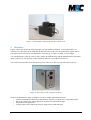
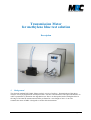
Figure 7: Peristaltic pump at housing. The flow cell
with the connected tubes is mounted a the right side.
The peristaltic pump is integrated in a UV-stable aluminium housing so that it can be used directly in the
illumination chamber. There are screws at the housing to mount the flow cell. The pump is powered by a
wall power supply.
Notes:
(1) Especially when you replace the tubes it can happen that air is getting into them. Please make
sure that air is not accumulating at the transmission window of the flow cell where it would
distort the measurement. The elimination of air is easier if you turn the flow cell in an upright
position as shown in figure 3. If an air bubble is fixed to the transmission window (i.e. in a
stream burble), you can try to resolve and remove it by snapping with your finger and actively
moving the tubes.
(2) Please take care to keep the transmission window in a clean state.
(3) If the flow cell is wetted with methylene blue or other dyes you should recirculate it with distilled
water in order to avoid a dry coating.
5.3. Sample container
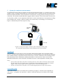
Figure 8 shows the example of a sample container which can be integrated into a closed loop. For an easy
performance of a continuous measurement we have equipped the container (diameter: 80 mm, height: 45
mm) with a top frame which carries tube connectors and a UV transmitting glass cover. The container
accepts samples with an area of 50x50 mm².
Note: The absorption of the chosen UV glass cover at a wavelength of 365 nm is about 11%.
The test solution in the container can be circulated through a flow cell by means of a peristaltic pump to
which the bracket for the transmission measurement can be connected. We have selected tubes which do
not absorb methylene blue and which are stable against UV illumination.
Transmission meter user manual
version 2 – 25.04.2013
page 6 of 8