1
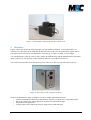
Figure 3: Combination of mounting bracket with flow cell
4.
Electronics
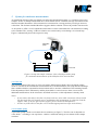
Figure 4 shows the front side of the electronic box with different elements. At the bottom there are
connectors for the cables of the LED and the photo-diode as well as for the transmission signal output.
The signal can be read out by any multimeter. Alternatively, it can be recorded on a data logger.
Two potentiometers at the top can be used to adjust the LED intensity and the amplification of the photodiode, respectively. The function of the saturation indicator is described in section 4.1.
The on/off switch and the connection for the power cable are on the rear side of the electronic box.
Figure 4: Electronics of the transmission meter
We have implemented a couple of features in order to enable stable measurements:
•
Current stabilization of the LED (compensation of power variations due to temperature drift)
•
Electronic chopper for offset suppression against room and ambient light
•
Electronic noise suppression
•
Coloured glass filter (Schott OG530) for suppression of ambient light
Transmission meter user manual
version 2 – 25.04.2013
page 3 of 8