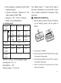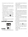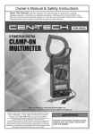
1
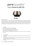
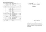
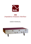
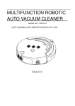
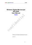
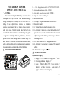
INSULATION TESTER
INSTUCTION MANUAL
一、GENERAL
This instrument adopts the DC Voltage convertor of low
consumption and high converter ratio inductance energy
storage, to change the 9V Voltage to 250V/500V/1000V DC
Voltage. It uses digital bridge to make the insulation
resistance measurement had the features of user-friendly,
high extent range, backlight display, data hold and auto
power off. The whole instrument is stylish and superior grade
in appearance and high stable in performance, it can be
operated by both hands through using a shoulder strap. It is
most suitable for the needs of insulation resistance check,
such as electric, cable, electrical and mechanical equipment,
telecommunication equipment and electrical facilities.
二、FRONT PANEL DESCRIPTION
M
15
1、2、3、4、Voltage selection switch(AC750V/500V/250V/1000V).
5、Resistance Range selection switch(RANGE).
6、Power switch:auto-lock power switch(POWER).
7、High voltage indicator:LED display.
8、Measurement button.
9、LCD display:Display the measured data and units。
10、Instrument model.
11、L: Terminal for connecting the measured circuit.
12、G:Terminal for protection, connect the electrode wire of
protection loop to “G” terminal when the measured
object is required to add the protection loop to eliminate
the leakage effect.
13、ACV: Input terminal of AC Voltage measurement.
14、E:Terminal for connecting the ground of the measured
object.
15、Terminal of AC adaptor(
)
。
三、TECHNIC PROPERTY
1、General Property
(1)Display:84.8×59.8mm LCD display, max.“1999”
。
(2)Over range indicator:display“1”
。
(3)Power:5# battery LR6 (1.5V) ×6 (or external AC
adaptor), no battery indicator 。 Auto power off
(approx. 15miutes after turning on)
-1-
(4)Power consumption:consumption is less than 300mw
at unload measurement.
( 5 ) Operation environment : Temperature 0C — 40C.
Relative humidity 30%RH—85RH.
(6)Dimension:175(L) ×110(W) ×70(D) mm。
(7)Weight:630 g (including batteries).
2、Technical property
Measured
250V±20%
500V±20%
1000V±20%
▇
0.1MΩ—
0.1MΩ—
0.1MΩ—
20MΩ
50MΩ
100MΩ
▃
20MΩ—
50MΩ—
100MΩ—
500MΩ
1000MΩ
2000MΩ
Note:Median resistance——to ensure that the voltage of
both sides of measurement is not less than 90% of lower
limit of resistance measurement of measurement voltage
normal value
四、OPERATION DESCRIPTION:
1、Open the battery case and set up 6pcs of 5# batteries
(see the following pictures), note the polarity of
batteries.
voltage
RANGE
Accuracy
±(4% of reading ± 2 digits)
Shot current
1.8mA
1.8mA
1.6mA
Median
2 MΩ
2MΩ
5MΩ
2、Press the button of“POWER”.
resistance
Terminal
L .
E
position
ACV750V Accuracy:±(1.0% of reading + 6 digits).
Terminal position:ACV G
Input impedance: 1MΩ。
Frequency response:
(50~200)Hz
3、Select the right voltage (250V/500V/1000V/AC750V) according
to the requirement of measurement.
4、Select the right range (RANGE) (except AC750V), according to
the requirement of measurement.
5、Connect the electrode of the measured object to the relative
terminal of the instrument.
-2-
6、When measuring cable, connect G Terminal to the protection
loop.
7、Press the button of measurement and start it, turn the
knob right to lock the button; when the value is stable,
get the reading from LCD.
8 、 Connect the input line “E” to the ground of the
measured object, and “L” to the circuit of the
measured object; require line “L” to hang in the air.
9、2000MΩ。When “1” is displayed, over range is indicated,
and should turn to the higher range to get reading;
When the range button is in “
“position, it
expresses that the insulated resistance exceeds
2000MΩ.
10、Hang the instrument on your neck to save your hands
to make measurement.
五、METHOD TO MEASURE THE INSULATED RESISTANCE:
六、SAFETY NOTES:
1、When voltage measurement selection button does not be
pressed, it is possible to appear the high voltage at the
output voltage terminal.
2、When measuring, first check the measurement voltage
selection and if the indication of the measurement
voltage on LCD is in accordance with the voltage
needed
3、To ensure the safety of operation, the operation cannot be
done until the measured object removed from the power
supplied by the electricity grid system, and should be
discharged fully to testify that the measured object does
not have any danger of power.
4、When measuring, it is not allowed to handle the terminal
of measurement to make sure the accuracy of reading
and personal safety.
5、Keep the instrument away from the high temperature
place, and from the direct sunshine to avoid affecting
the life of the LCD.
6、 When low battery symbol of “
” appears, please
replace the batteries in time. Take the batteries out
when storage to avoid the leakage of batteries to
damage the instrument.
7、When unload, reading is normal, it won’t affect the
measurement.
-3-
8、When measuring MΩ, if the reading is unstable, it is
likely caused by the interference of surrounding and
unsteadiness of the insulated materials, it will make the
reading stable to connect the “G” terminal to the shield
side of the measured object
9、To ensure the safety of measurement and reduce the
interference, the test leads adopt silicone rubber
materials, please do not change the leads at will.
10、When the external AC adaptor supplies the power, the
inside batteries are disconnected and the batteries can’t
be charged at the time. Note: please select (
)
power supply method.
七、SETS OF INSTRUMENT
1、Digital Insulation Tester
1pc
2、10A test leads
1set
3、5# battery(1.5V)×6
6pcs
4、Operation Manual
1copy
5、Shoulder strap
1pc
八、FAULT ELIMINATION
If the instrument can’t work properly, the below
methods can help you to solve the general problems quickly.
If the fault still can’t be eliminated, please contact the
maintenance centers or distributors.
Fault
Solution
●
No display
Power off-please turn on the
power
symbol
●
Replace the batteries
●
Replace the batteries
●
Replace the batteries
appearance
Error value
The instruction manual is subject to change without notice.
The contents in the instruction manual are considered to be
correct, if the user find any errors or pretermissions, etc.,
please contact the manufacturer.
The manufacturer hereby will not be responsible for any
accident and damage caused by the improper operation.
The functions described in this instruction manual do not be
the reason for special usage.
MB-60B+-50
-4-