1
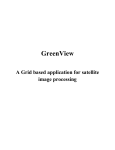
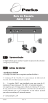
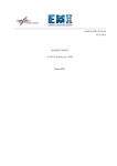
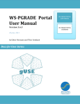
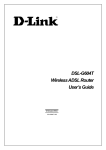
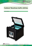
PACKAGE CONTENTS
» Scanner unit
» QIG
» User’s manual » TV- out cable
» USB 2.0 cable
» SD card (4G)
» Gel shovel
» Gel cutting knife
» A/C adapter (12V, 1.5A, DC)
» Sample tray (in box)
» Amber filter board (in box)
» Black plastic board (in box)
Upper lid
Card reader/Standalone
LCD display
Up/Down, Left/Right menu button
SD/SDHC card slot
Blue Light/White Light selection switch
SCANNER COMPONENTS
Front (Figure 1):
» Up/Down, Left/Right menu button
» SD/SDHC card slot
» Scan button
» Blue Light/White Light selection switch
» Card Reader/Standalone (Regular operation mode)
» LCD display
» Upper lid
Back (Figure 2):
» DC power
» USB 2.0 port
» TV-Out port
Inside (Figure 3):
» Upper lid
» Lighting area
Figure 1
Scan button
Upper lid
Lighting area
DC power
USB 2.0 port
TV-Out port
Figure 2
Figure 3
1
SETUP
1. Remove all tapes used to hold items in place
for shipping.
2. Place scanner unit on flat surface.
3. Insert SD/SDHC card (up to 32GB).
4. Connect power source (see Figure 2) –
connect AC adapter to back of unit then
plug into electrical outlet.
5. The Menu Mode icon will be displayed on
the top left side of the display (Figure 4).
6. Wet the gel and place gel at the center of the
sample tray (Figure 5)
7. Place sample tray into the Lighting area
of the system (Figure 6). Caution: Do not
place the gel directly on the surface of the
Lighting area. Fail to do so may lead LED
damage caused by buffer leakage.
8. Start to adjust the image condition and scan.
Menu mode icon
Figure 4
Lighting area
Sample tray
Figure 5
Place the gel at center of the sample tray
2
Figure 6
Place sample tray into the Lighting Area
of the system
SCANNING GEL
1.
2.
3.
4.
5.
6.
7.
8.
In “Scanning Mode”
, lift scanner lid and take the
sample tray out of the scanner.
Wet the gel and place the gel at the center of the sample
tray.
Place the sample tray back to the Lighting area of the
scanner. Caution: Do not place the gel directly on the
surface of the Lighting Area. Failing to use the tray may
cause buffer leakage and damage the LED(Figure 6).
Slide the black plastic board into the groove of the white
backlight to block the white light on the lid* (Figure 7).
Close the scanner lid.
Slide the Light Selection Switch on the front side of the
scanner to choose blue light source for scanning stained
gel.
Set and adjust the desired image quality through the
Functional Menu if necessary (Please check “Functional
Descriptions” section for the details of all functions).
Press SCAN button, green LED will flash and “CAPTURING”
will be displayed on the screen. The scanned image will
automatically save to SD card.
Black plastic board
Scanning of the gel sample is now complete.
(*: it is suggested to slide the black plastic board to block the white backlight on
the lid for fluorescent stained gel scanning. For colorimetric gel scanning, leave
the white backlight unblocked on the lid.)
White backlight
Figure 7
Slide the black plastic board to avoid the
background light for fluorescent stained
gel scanning. For colorimetric gel
scanning, leave the white backlight
unblock on the lid.
3
SCANNING WESTERN BLOT/COLORIMETRIC STAINED GEL:
1. In “Scanning Mode”
, lift scanner lid and take the sample tray out of the scanner.
2. Place the blot membrane at the center of the tray for which the signal side of the membrane
is facing toward the bottom of the tray.
3. Place the sample tray back into the Lighting area of the scanner.
4. Slide the black plastic board into the groove of the white backlight to block the white light on
the lid*.
5. Close the scanner lid.
6. Slide the Light Selection Switch on the front side of the scanner to select the white light
source for stained gel scanning.
7. Set “Transmitted” or “Epi* item through Functional Menu (Please check “LED Lighting” of
“Functional Descriptions” section for details of turn-on of “Transmitted” or “Epi” application ).
8. Adjust the desired image quality through the Functional Menu if necessary (Please check
“Functional Descriptions” section for the details of all functions).
9. Press SCAN button, green LED will flash and “CAPTURING” will be displayed on the screen.
The scanned image will automatically be saved to SD card.
Scanning of the blot is now complete.
*: “Transmitted” mode is to scan the gel stained with colorimetric stain such as the SDS-PAGE gel
stained with coomassie blue stain.
4
BROWSE SCANNED IMAGES/DELETE SCANNED IMAGES
Examine Scanned Images
a. When
icon displays on top left corner of the screen, press “OK” to get into
functional options.
b. When “Scan Mode” icon is highlighted
, press “OK” again to get into “Play Mode”.
c. The “Play Mode” icon
will display on top left corner of screen. The captured
images can then be reviewed one by one by pressing right arrow button.
Delete Scanned Images
a. When viewing the image that needs to be deleted, press “OK” to get into
Function Descriptions II.
b. Press right arrow button to choose “Edit Mode”
.
c. Press up/down arrow button to choose “Delete”. Press right arrow button to select (yes/no)
to delete the file.
d. Press up/down arrow button to select “Yes”. Press “OK” to save the setting. The image
is thus deleted.
5
INSTALLATION OF AMBER FILTER BOARD
Filter board hanging tab
Glite 900 BW is equipped with an amber filter
board for blue light protection and gel cutting
purposes. Open the lid and install the filter board
so the gel cutting task may be conducted.
1. Open the lid
2. Lift the lid to its maximum open angle
3. Position the amber filter board with the hole
for hanging on lid in front (Figure 8).
4. Place the amber filter board onto the filter
board hanging tab so the filter board may
hang as shown in Figure 9.
5. When hanging on the lid, make sure the two
small rods on the filter board are placed
closely against the lid.
6. The installation is completed. One may turn
on blue LEDs for further gel cutting purpose
by using the provided gel cutting knife.
Amber Filter Board
Figure 8
Small rod
Figure 9
6
ACCESS STORED SCANNED IMAGE FILES WITH COMPUTER
The files stored on the SD/SDHC card can be accessed by a computer.
1. Connect the provided USB cable to the computer USB port.
2. Connect the other end of the cable to the USB port on the back of the scanner.
3. Switch Card reader/Standalone to Card Reader mode.
4. Through the operating system on PC, the contents of the SD/SDHC card will
be available as removable media.
5. Copy the files to PC’s hard drive for storage or for further use.
DISPLAY SCANS ON TV
The display from the scanner can be displayed on a television rather than the built in scanner
preview screen using the AV video port.
1. Set the television to AV mode (see TV documentation for details).
2. Connect the included TV-Out cable to the video port on the TV.
3. Connect the other end of the cable to the TV port on the back of the scanner.
4. Video output from the scanner can now be seen on the connected TV including the full menu
interface.
7
Functional Menu: When image display on screen in yellow border, press “OK” button so the
functional icon will show on the left upper corner.
A. Function Descriptions I:
Scan Mode: The object is able to be scanned in this mode.
LED Lighting Mode: To select the white light application for
Transmitted/Epi image scan, respectively (Note: this mode is available only when
white light application is selected.)
Exposure Mode: To adjust the exposure time frame in this mode.
8
B/W Switch Mode: To scan/display the image in colorimetric/monochrome and
normal/invert mode. Default setting: monochrome (black & white)
Set Up Mode: To set up the following parameters:
a. LCD: Dark, Normal, Bright
b. Display: NTSC, PAL (NTSC = USA, PAL = Europe)
c. Quality: S. Fine, Fine, Normal (JPEG Compression)
d. Size: 12M, 9M, 5M, 1M (Megapixels, “9M” is default setting)
e. Power Save: 1 min, 3 min, 5 min, 10 min, off (Power shut off)
f. Language: English, 繁體中文, 日本語
g. Format: Yes, No. (Format SD card)
h. Reset: Yes, No. (Reset all current settings back to factory default)
Functional Menu:
B.
Function Descriptions II:
Play Mode: To play the captured images. To examine the captured image.
Auto Play Mode: To automatically play the captured images one by one.
Edit Mode: To edit the captured images (such as to rotate or to delete the captured
image, etc…)
Preview Mode: To preview the captured images in a multi image thumbnail panel.
Set Up Mode: Same as the “Set Up Mode” functions in Function Descriptions I.
9
Function Descriptions I:
“Scan Mode”
When
icon displays on top left corner of the screen, the object is ready to be scanned.
“LED Lighting Mode”
*
a. When in “Scan Mode”, press “OK” to get into functional option list.
b. Press right arrow button to choose “LED Lighting Mode”
. ”
c. Press up or down arrow button to choose light source (Transmitted & Epi1).
d. Press “OK” to save the setting.
*: “LED Lighting Mode” Is only available when switching to white light application.
1: “Transmitted” mode is to scan the gel stained with colorimetric stain such as the SDS-PAGE gel
stained with coomassie blue stain.
10
“Exposure Mode”
a. When
option list.
icon displays on top left corner of the screen, press “OK” to get into functional
b. Press right arrow button to choose “Exposure Mode”
.
c. Press up or down arrow button to choose the desired exposure level.
d. When the desired exposure level is selected, press “OK” to get back to “Scan mode”.
“B/W Switch Mode”
a. When
option list.
icon displays on top left corner of the screen, press “OK” to get into functional
b. Press right arrow button to choose “B/W Switch Mode”
.
c. Press up or down arrow button to choose to select the desired display mode (color or B & W;
color invert or B & W invert).
d. Press “OK” again to return to “Scan Mode”.
*: The default setting of the scanner is Black & White.
11
“Set Up Mode”
a. When
icon displays on top left corner of the screen, press “OK” to get into functional
option list.
b. Press right arrow button to choose “Set Up Mode”
.
C. Press down arrow button to get into “Setup Menu” and select the desired setting item.
d. Press right arrow button to get into setting mode. Then press up and down arrow button
to select the desired setting. Press “OK” to save the setting.
e. Press down arrow button to select other setting mode; or press “OK” again to return to
“Scan Mode”.
Setup Menu and related setting items:
a. LCD: Dark, Normal, Bright
b. Display: NTSC, PAL (NTSC = USA, PAL = Europe)
c. Quality: S. Fine, Fine, Normal (JPEG Compression)
d. Size: 12M, 9M, 5M, 1M (Megapixels, “9M” is default setting)
e. Power Save: 1 min, 3 min, 5 min, 10 min, off (Power shut off)
f. Language: English, 繁體中文,日本語
g. Format: Yes, No. (Format SD card)
h. Reset: Yes, No. (Reset all current settings back to factory default)
12
Function Descriptions II:
“Play Mode”
a. When
icon displays on top left corner of the screen, press “OK” to get into
functional options.
b. When “Scan Mode” icon is highlighted
, press “OK” again to get into “Play Mode”.
c. The “Play Mode” icon
will display on top left corner of screen. The captured
images can then be reviewed one by one by pressing right arrow button.
d. Press “OK” twice to get back to “Scan Mode” (It will take few seconds to complete
the process.)
“Auto Play Mode”
a. When in “Play Mode”
, press “OK” to get into functional option list.
b. Press right arrow button to choose “Auto Play Mode”
, then press “OK”.
c. The captured image will automatically display on LCD screen one by one.
13
“Edit Mode”
a. When in “Play Mode”
, press “OK” to get into functional option list.
b. Press right arrow button to choose “Edit Mode”
.
c. Press down arrow button to get into “Edit Menu” (Rotate/Delete) and select the
desired setting item.
d. Press right arrow button to get into setting mode:
Rotate: Right 900
Delete: No
0
Left 90
Yes
1800
Flip H.
Flip V.
e. Press up and down arrow button to select the desired setting. Press “OK” to save the setting.
f. Repeat step e. for “delete mode” setting or press “OK” again to return to “Play Mode”.
14
“Preview Mode”
a. When in “Play Mode”
, press “OK” to get into functional option list
b. Press right arrow button to choose “Preview Mode”
.
.
c. Press down arrow button to get into “Preview Menu” (1 X 1, 2 X 2, 3 X 3) and select the
desired setting item.
Preview Mode: 1 X 1 Display 1 image at a time
2 X 2 Display 4 images at a time
3 X 3 Display 9 images at a time
d. Press “OK” button to save the setting.
e. The captured images will display on the screen based on the selected preview format setting.
“Set Up Mode”
Same as the “Set Up Mode” described in “Function Descriptions I” on page 9.
15
16