1
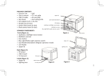
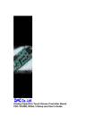
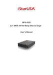
User’s Manual
FAS-BG LED BOX
PACKAGE CONTENTS
» Scanner unit
» User’s manual
» A/C power adapter (12V, 4.16A, DC)
» Amber filter board (included)
» Black plastic board (included)
» Gel tray w/o stopper (included)
Upper lid
Power Button
LCD display
Up/Down, Left/Right menu button
USB 2.0 Port
SCANNER COMPONENTS
Cyan Light/White Light selection switch
Front (Figure 1):
» Up/Down, Left/Right menu button
» USB 2.0 Port
» Scan button
» Cyan Light/White Light selection switch
» Power On/Off Button
» LCD display
» Upper lid
Scan button
Upper lid
Lighting area
Back (Figure 2):
» DC power
» USB 2.0 port
» VGA port
Inside (Figure 3):
» Upper lid
» Lighting area
» Lid Sensor
Figure 1
Lid Sensor
DC power
USB 2.0 port
VGA Our Port
Figure 2
Figure 3
2
SETUP
1.
2.
3.
4.
5.
6.
7.
8.
Remove all tapes used to hold items in place for shipping.
Place FAS-BG LED BOX unit on flat surface.
Connect power source – connect AC power adapter to back of unit then plug into electrical outlet.
Push power button.
Insert USB flash drive.
The Menu Mode icon will be displayed on the top left side of the display (Figure 4).
Place gel tray directly on the surface of the Lighting area (Figure 5).
Adjust the image condition and scan.
Sample Tray
Lighting Area
Menu icon
Figure 4
Figure 5
3
SCANNING FLUORESCENCE-STAINING GEL
1. In “Scanning Mode”
, lift the lid to open the
scanner.
2. Slide the black plastic board into the groove of the
white backlight to block the white light on the lid*
(Figure 7).
3. Close the scanner lid.
4. Slide the Light Selection Switch on the front side of
the scanner to choose cyan light source for scanning
stained gel.
5. Set and adjust the desired image quality through the
Functional Menu if necessary (Please check
“Functional Descriptions” section for the details of all
functions).
6. Press SCAN button, green LED will flash and
“CAPTURING” will be displayed on the screen. If
thermal printer had connected with FAS-BG LED BOX,
“Printing Yes/No” will be displayed on the screen. The
scanned image will automatically save to USB flash
drive.
Black plastic board
White backlight
Figure 7
Slide the black plastic board to avoid the background light for
fluorescent stained gel scanning.
Scanning of the gel sample is now complete.
(*: it is suggested to slide the black plastic board to block the white backlight on
the lid for fluorescent stained gel scanning.)
4
SCANNING WESTERN BLOT/COLORIMETRIC STAINED GEL:
1. In “Scanning Mode”
, lift the lid to open scanner.
2. Place the sample to the center of the viewing area. Close the lid.
3. Slide the Light Selection Switch on the front side of the scanner to select the white light
source for stained gel scanning.
4. Set “White Epi” or “White Back Light” item through Functional Menu (Please check “LED
Lighting” of “Functional Descriptions” section for details of turn-on of “White Epi” or “White
Back Light” application ).
5. Adjust the desired image quality through the Functional Menu if necessary (Please check
“Functional Descriptions” section for the details of all functions).
6. Press SCAN button, green LED will flash and “CAPTURING” will be displayed on the screen. If
thermal printer had connected with FAS-BG LED BOX, “Printing Yes/No” will be displayed on
the screen. The scanned image will automatically be saved to USB flash drive.
Scanning of the blot is now complete.
*: “White Back Light” mode is to scan the SDS-PAGE gel stained with coomassie blue and
preserved in a transparent media.
5
BROWSE SCANNED IMAGES/DELETE SCANNED IMAGES
Examine Scanned Images
a. When
icon displays on top left corner of the screen, press “OK” to get into
functional options.
b. When “Scan Mode” icon is highlighted
, press “OK” again to get into “Play Mode”.
c. The “Play Mode” icon
will display on top left corner of screen. The captured
images can then be reviewed one by one by pressing right arrow button.
d. Press Upper/down arrow button, the image can be zoomed in/out and be removed
upward/downward and leftward/rightward.
Delete Scanned Images
a. When viewing the image that needs to be deleted, press “OK” to get into Function Descriptions II.
b. Press right arrow button to choose
“Edit Mode”
c. Press up/down arrow button to choose “Delete”. Press right arrow button to select (yes/no)
to delete the file.
6
d. Press up/down arrow button to select “Yes”. Press “OK” to save the setting. The image is deleted.
INSTALLATION OF AMBER FILTER BOARD
Filter board hanging tab
FAS-BG LED BOX is equipped with an amber filter
board for cyan light protection and gel cutting
purposes. Open the lid and install the filter board
so the gel cutting task may be conducted.
1. Open the lid, cyan light will auto turn off
2. Lift the lid to its maximum open angle
3. Position the amber filter board with the hole
for hanging on lid in front (Figure 8).
4. Place the amber filter board onto the filter
board hanging tab so the filter board may
hang as shown in (Figure 9).
5. When hanging on the lid, make sure the two
small rods on the filter board are placed
closely against the lid.
6. The installation is completed. One may turn
on cyan LEDs by “Scan button” for further gel
cutting purpose.
Amber Filter Board
Figure 8
Small rod
Figure 9
DISPLAY SCANS ON Monitor or Projector
The display from the scanner can be displayed on a television rather than the built-in scanner
preview screen using the VGA port.
1. Set the television to VGA mode (see monitor documentation for details).
2. Connect the included VGA cable to the video port on the monitor.
3. Connect the other end of the cable to the VGA port on the back of the scanner.
4. Video output from the scanner can now be seen on the connected monitor including the full
menu interface.
8
Functional Menu: When image display on screen in yellow border, press “OK” button so the
functional icon will show on the left upper corner.
A. Function Descriptions I:
Scan Mode: The object is able to be scanned in this mode.
LED Lighting Mode: To select the white light application for
White Epi/White Back Light image scan, respectively (Note: this mode is available
only when white light application is selected.)
Exposure Mode: To adjust the exposure time frame in this mode.
BW/Color Switch Mode: To scan/display the image in B&W/B&W invert mode.
Default setting: monochrome (black & white)
9
Set Up Mode: To set up the following parameters:
a. LCD: Dark, Normal, Bright
b. Display: LCD, VGA
c. Video Output: 800x600, 1024x768
d. Filename: Setup/Filename
e. Save Format: TIF, JPG, BMP, (“JPG” is default setting)
f. Quick View: 1 sec, 2sec, 3 sec, off (“2sec” is default setting)
g. Slide Show Cycle: 2 sec, 3sec, 5 sec, 10 sec (“2sec” is default setting)
h. Power Save: 1 min, 3 min, 5 min, 10 min, off (“1 min” is default setting)
i. Language: English, Japanese
j. Date: setup date yyyy/mm/dd
k. Time: setup time hh/mm/ss
l. Reset: Yes, No. (Reset all current settings back to factory default)
m. About: product name, S/W version, F/W version, Update FW, CWD Version
10
Functional Menu:
B.
Function Descriptions II:
Play Mode: To play the captured images. To examine the captured image. Press
Upper/down arrow button, the image can be zoomed in/out and be moved
upward/downward and leftward/rightward.
Auto Play Mode: To automatically play the captured images one by one.
Edit Mode: To edit the captured images (rotate, delete, and flip)
Preview Mode: To preview the captured images in a multi image thumbnail panel
(1 x 1, 2 x 2, 3 x 3).
Set Up Mode: Same as the “Set Up Mode” functions in Function Descriptions I.
11
Function Descriptions I:
“Scan Mode”
When
icon displays on top left corner of the screen, the object is ready to be scanned.
“LED Lighting Mode”
*
a. When in “Scan Mode”, press “OK” to get into functional option list.
b. Press right arrow button to choose “LED Lighting Mode”
. ”
c. Press up or down arrow button to choose light source (White Epi or White Back Light 1).
d. Press “OK” to save the setting.
*: “LED Lighting Mode” Is only available when switching to white light application.
1: “White Back Light” mode is to scan the SDS-PAGE gel stained with coomassie blue and preserved in a
transparent media.
“Exposure Mode”
a. When
option list.
icon displays on top left corner of the screen, press “OK” to get into functional
b. Press right arrow button to choose “Exposure Mode”
.
c. Press up or down arrow button to choose the desired exposure level.
d. When the desired exposure level is selected, press “OK” to get back to “Scan mode”.
“BW/Color Switch Mode”*
a. When
option list.
icon displays on top left corner of the screen, press “OK” to get into functional
b. Press right arrow button to choose “BW/Color Switch Mode”
.
c. Press up or down arrow button to choose to select the desired display mode (B&W;
B&W invert).
d. Press “OK” again to return to “Scan Mode”.
*: The default setting of the scanner is Black & White.
13
“Set Up Mode”
a. When
icon displays on top left corner of the screen, press “OK” to get into functional
option list.
b. Press right arrow button to choose “Set Up Mode”
.
C. Press down arrow button to get into “Setup Menu” and select the desired setting item.
d. Press right arrow button to get into setting mode. Then press up and down arrow button
to select the desired setting. Press “OK” to save the setting.
e. Press down arrow button to select other setting mode; or press “OK” again to return to
“Scan Mode”.
Setup Menu and related setting items:
a. LCD: Dark, Normal, Bright
b. Display: LCD, VGA
c. Video Output: 800x600, 1024x768d.
d. Filename: Setup/Filename
e. Save Format: TIF, JPG, BMP, (“JPG” is default setting)
f. Quick View: 1 sec, 2sec, 3 sec, off (“2sec” is default setting)
g. Slide Show Cycle: 2 sec, 3sec, 5 sec, 10 sec (“2sec” is default setting)
14
Setup Menu and related setting items (cont’d):
h. Power Save: 1 min, 3 min, 5 min, 10 min, off (“1 min” is default setting)
i.
Language: English, Japanese
j.
Date: setup date yyyy/mm/dd
k. Time: setup time hh/mm/ss
l.
Reset: Yes, No. (Reset all current settings back to factory default)
m. About: product name, S/W version, F/W version, Update FW, CWD Version
15
Function Descriptions II:
“Play Mode”
a. When
icon displays on top left corner of the screen, press “OK” to get into
functional options.
b. When “Scan Mode” icon is highlighted
, press “OK” again to get into “Play Mode”.
c. The “Play Mode” icon
will display on top left corner of screen. The captured
images can then be reviewed one by one by pressing right arrow button.
d. Press Upper/down arrow button, the image can be zoomed in/out and be removed
upward/downward and leftward/rightward.
e. Press “OK” twice to get back to “Scan Mode” (It will take few seconds to complete
the process.)
16
“Auto Play Mode”
a. When in “Play Mode”
, press “OK” to get into functional option list.
b. Press right arrow button to choose “Auto Play Mode”
, then press “OK”.
c. The captured image will automatically display on LCD screen one by one.
d.. Press “OK” to get into functional option list again.
17
“Edit Mode”
a. When in “Play Mode”
, press “OK” to get into functional option list.
b. Press right arrow button to choose “Edit Mode”
.
c. Press down arrow button to get into “Edit Menu” (Rotate/Delete) and select the
desired setting item.
d. Press right arrow button to get into setting mode:
Delete: No
Rotate: Right 900
Yes
Left 900
1800
Flip: Horizontal
Flip: Vertical
e. Press up and down arrow button to select the desired setting. Press “OK” to save the setting.
f. Repeat step e. for “delete mode” setting or press “OK” again to return to “Play Mode”.
18
“Preview Mode”
a. When in “Play Mode”
, press “OK” to get into functional option list
b. Press right arrow button to choose “Preview Mode”
.
.
c. Press down arrow button to get into “Preview Menu” (1 X 1, 2 X 2, 3 X 3) and select the
desired setting item.
Preview Mode: 1 X 1 Display 1 image at a time
2 X 2 Display 4 images at a time
3 X 3 Display 9 images at a time
d. Press “OK” button to save the setting.
e. The captured images will display on the screen based on the selected preview format setting.
“Set Up Mode”
Same as the “Set Up Mode” described in “Function Descriptions I” on page 11.
19
Hardware Specifications
I. Image Capturing
Unit
Sensor
CMOS Sensor
Resolution
9M Pixels
Exposure Time
0.2~ 10.1 sec (21 Scales)
Image Storage
USB flash drive
View Area
16 x 10.5cm (Fixed Lens)
VI. Interface
Display Panel
Output
Build-in 2.7” TFT LCD
1. USB 2.0 port x2
(Thermal printer and
USB flash drive )
2. VGA out
( 800x600, 1024x768)
II. Lens and Filter
Filter Turret
Emission Filter
Manual-Driven, 2
position
518nm Amber Filter
III. Lighting
Blue Light
510 nm cyan LED Light
Epi White Light
LED White Light
White Back Light LED White Light Panel
V. General Info
Power
Dimension
(WxHxD)
Gel Tools
Weight
Certification
AC Adaptor, 12V/4.16A
207x229x254mm
( 8.14 x 9.02 x 10 inch)
Amber View Shield
Gel Tray
3.2Kg (7.05 lb)
CE, FCC
20
User’s Manual
FAS-BG LED BOX
Made in Taiwan
NIPPON Genetics Co.Ltd
Koraku Mori Bldg.18F, 4-14 Koraku 1-Chome,
Bunkyo-ku Tokyo 112-0004, Japan
Phone: +81 (0)3-3813-0961
fax: +81 (0)3-3813-0962
e-mail: [email protected]
web: http://www.genetics-n.co.jp
21