1
ÎÎ
GE Fanuc Automation
Programmable Control Products
Hand-Held Programmer
for Series 90 -30/20/Micr o
Programmable Controllers
t
User’s Manual
GFK-0402G
Februar y 1996
GFL–002
Warnings, Cautions, and Notes
as Used in this Publication
Warning
Warning notices are used in this publication to emphasize that
hazardous voltages, currents, temperatures, or other conditions that
could cause personal injury exist in this equipment or may be
associated with its use.
In situations where inattention could cause either personal injury or
damage to equipment, a Warning notice is used.
Caution
Caution notices are used where equipment might be damaged if care is
not taken.
Note
Notes merely call attention to information that is especially significant to
understanding and operating the equipment.
This document is based on information available at the time of its publication. While
efforts have been made to be accurate, the information contained herein does not
purport to cover all details or variations in hardware or software, nor to provide for
every possible contingency in connection with installation, operation, or maintenance.
Features may be described herein which are not present in all hardware and software
systems. GE Fanuc Automation assumes no obligation of notice to holders of this
document with respect to changes subsequently made.
GE Fanuc Automation makes no representation or warranty, expressed, implied, or
statutory with respect to, and assumes no responsibility for the accuracy, completeness,
sufficiency, or usefulness of the information contained herein. No warranties of
merchantability or fitness for purpose shall apply.
The following are trademarks of GE Fanuc Automation North America, Inc.
Alarm Master
CIMPLICITY
CIMPLICITY 90–ADS
CIMPLICITY PowerTRAC
CIMSTAR
GEnet
Genius
Genius PowerTRAC
Helpmate
Logicmaster
Modelmaster
ProLoop
PROMACRO
Series One
Series Three
Series Five
Copyright 1990 - 1996 GE Fanuc Automation North America, Inc.
All Rights Reserved
Series Six
Series 90
VuMaster
Workmaster
restart lowapp ARestart oddapp: ARestarts for autonumbers that do not restart in
each chapter. figure bi level 1, reset table_big level 1, reset chap_big level 1, reset1
Lowapp Alwbox restart evenap:A1app_big level 1, resetA figure_ap level 1, reset
table_ap level 1, reset figure level 1, reset table level 1, reset these restarts
oddbox reset: 1evenbox reset: 1must be in the header frame of chapter 1. a:ebx, l 1
resetA a:obx:l 1, resetA a:bigbx level 1 resetA a:ftr level 1 resetA c:ebx, l 1 reset1
c:obx:l 1, reset1 c:bigbx level 1 reset1 c:ftr level 1 reset1 Reminders for
autonumbers that need to be restarted manually (first instance will always be 4)
let_in level 1: A. B. C. letter level 1:A.B.C. num level 1: 1. 2. 3. num_in level 1: 1. 2.
3. rom_in level 1: I. II. III. roman level 1: I. II. III. steps level 1: 1. 2. 3.
Chapter
1 Introduction to the Hand-Held Programmer
1
The major features of the Hand-Held Programmer (catalog number IC693PRG300) for
the Series 90-30, 90-20 and Micro Programmable Logic Controllers include:
D
D
D
D
Creating a Statement List program, including insert, edit and delete functions.
D
D
D
D
D
D
D
D
D
Monitoring reference data or I/O point status while viewing the logic program.
D
Starting or stopping the PLC from any mode of operation.
Making on-line program changes.
Searching a logic program for instructions and/or machine references.
Performing optional dual use checking of discrete output references when
instructions are entered.
Monitoring reference data in table form in binary, hexadecimal, or decimal format.
Monitoring register reference data in timer/counter format.
Making on-line reference data changes.
Four PLC access privilege levels
Using the OEM protection key.
Configuring I/O modules.
Viewing PLC scan time, firmware revision code, and current logic memory usage.
Loading, storing, and verifying program logic and configuration from/to/with the
Series 90 Memory Card or EEPROM.
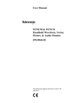
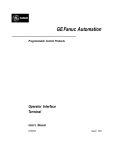
Keypad
The keypad on the Hand-Held Programmer consists of 42 keys, arranged as a matrix of
six keys across by seven keys down. The keypad is color-coded for easier identification
of the different keys. Becoming familiar with the programmer keys and their functions
will increase your programming efficiency.
Some of the keys have multiple uses, depending on the current operating mode and
function. A description of the valid keys and their usage is included in chapter 2,
Operation, and also in the beginning of each chapter of this manual.
GFK-0402G
1-1
1
LCD Screen
Information is displayed on an LCD screen which is two lines by sixteen characters in
size. The contents of the screen depends on the current operating mode and function.
The intensity of the screen can be increased or decreased by inserting a Phillips-head
screwdriver into the small square opening on the right side of the programmer and
turning it to the right or left, accordingly.
PLC Communications
The Hand-Held Programmer communicates with an attached PLC through an RS-422
compatible port. The cable connection supplies power to the Hand-Held Programmer
and indicates to the PLC that a Hand-Held Programmer is attached. Please refer to
chapter 2, Operation, for cable connection information.
Memor y Card Interface
An interface to a removable memory card is provided. This removable memory card is a
Series 90 Memory Card (catalog number IC693ACC303). The interface is used for
storage and/or retrieval of program logic and configuration data. Detailed information
on using the memory card to read, write, and verify data can be found in chapter 2.
Operating Modes
The Hand-Held Programmer supports four major operating modes:
Mode 1. Program Mode:
Program mode is used to create, alter, monitor, and debug Statement List (SL) logic
programs. Interaction (Read, Write, and Verify) with a Series 90 Memory Card or
EEPROM is also possible in program mode. Please refer to chapter 5, Program Edit, for
additional information on using program mode.
Mode 2. Data Mode:
Data mode enables you to view and alter values in various reference tables. Numerous
display formats are also supported. Please refer to chapter 6, Reference Tables, for
additional information on using data mode.
Mode 3. Protection Mode:
Protection mode enables you to control access to (protect) a programmable logic
controller, including program logic, reference data, and configuration information. The
use of this mode is optional. Additional information on protection mode can be found in
chapter 7, PLC Control and Status.
Mode 4. Configuration Mode:
In configuration mode, you can define the makeup of I/O modules in the PLC, including
both those I/O modules already installed as well as those to be installed at a later time.
Additional information on configuration mode can be found in chapter 3, PLC
Configuration, and chapter 4, I/O Configuration.
1-2
Hand-Held Programmer for Series 90-30/20/Micro Programmable Controllers User’s Manual – February 1996
GFK-0402G
1
Several functions may be performed independent of the current mode of operation.
These functions include mode selection and starting or stopping the PLC. Please refer to
chapter 7, PLC Control and Status.
References
The data used in an application program is stored as either register or discrete
references. When entering a statement list program you must assign references to data
in the PLC system. A reference specifies both a memory type and a precise location
within that memory type. For example: %I0001 specifies address 1 in discrete input
memory and %R0256 specifies address 256 in register memory.
The %I symbol is used by the PLC to distinguish machine references from nicknames
(the % symbol is not entered or displayed on the HHP).
The valid register and discrete references that are used with the Series 90-30 and Series
90-20 programmable logic controllers are described in the following two tables.
Table 1-1. Register References
Type
Description
%R
The prefix %R is used to assign system register references, which will store program data such as the
results of calculations.
%AI
The prefix %AI represents an analog input register. This prefix is followed by the register address of the
reference (for example, %AI0015). An analog input register holds the value of one analog input or other
value.
%AQ
The prefix %AQ represents an analog output register. This prefix is followed by the register address of
the reference (for example, %AQ0056). An analog output register holds the value of one analog output or
other value.
Note
All register references are retained across a power cycle to the CPU.
GFK-0402G
Chapter 1 Introduction to the Hand-Held Programmer
1-3
1
Table 1-2. Discrete References
Type
%I
Description
The %I prefix represents input references. This prefix is followed by the reference’s address in the
input table (for example, %I0121). %I references are located in the input status table, which stores the state
of all inputs received from input modules during the last input scan.
A reference address is assigned to discrete input modules using the Logicmaster 90-30/90-20
configuration software or the Hand-Held Programmer. Until a reference address is assigned, no data
will be received from the module.
%Q
The %Q prefix represents physical output references. The dual use coil checking function of the HHP
checks for multiple uses of %Q references with relay coils or outputs on functions. Beginning with
Release 3 of Series 90-30 and Release 2 of Series 90-20 firmware, you can select the level of coil
checking desired (SINGLE, WARNMULTIPLE, or MULTIPLE). Refer to Chapter 3 for more information
about this feature.
The %Q prefix is followed by the reference’s address in the output table (for example, %Q0016). %Q references are located in the output status table, which stores the state of the output references as last set by the
application program. This output status table’s values are sent to output modules at the end of the
program scan.
A reference address is assigned to discrete output modules using the Logicmaster 90-30/20/Micro
configuration software or the Hand-Held Programmer. Until a reference address is assigned, no data is
sent to the module. A particular %Q reference may be either retentive or non-retentive.
%M
The %M prefix represents internal references. The dual use coil checking function of the HHP software
checks for multiple uses of %M references with relay coils or outputs on functions. Beginning with
Release 3 of Series 90-30 and Release 2 of Series 90-20 firmware, you can select the level of coil checking desired (SINGLE, WARNMULTIPLE, or MULTIPLE). Refer to Chapter 3 for more information about
this feature. A particular %M reference may be either retentive or non-retentive.
%T
The %T prefix represents temporary references. These references are never checked for multiple coil
use and can, therefore, be used many times in the same program even when coil use checking is
enabled.
Because this memory is intended for temporary use, it is never retained through power loss or
RUN-to-STOP-to-RUN transitions and cannot be used with retentive coils.
%S
The %S prefix represents system status references. These references are used to access special PLC
data, such as timers, scan information, and fault information. System references include %S, %SA,
%SB, and %SC references.
%S, %SA, %SB, and %SC can be used on any contacts.
%SA, %SB, and %SC can be used on retentive coils -(M)-.
%S can be used as a word or bit-string input reference to functions or function blocks.
%SA, %SB, and %SC can be used as a word or bit-string input or output reference to functions and
function blocks .
%G
The %G prefix represents global data references. These references are used to access data shared
among several PLCs. %G references can be used on contacts and retentive coils because %G memory
is always retentive. %G cannot be used on non-retentive coils.
Transitions and Overrides
The %I, %Q, %M, and %G user references have associated transition and override bits.
%T, %S, %SA, %SB, and %SC references have transition bits, but not override bits. The
CPU uses transition bits for counters and transitional coils. Note that counters do not
use the same kind of transition bits as coils. Transition bits for counters are stored within
the locating reference.
1-4
Hand-Held Programmer for Series 90-30/20/Micro Programmable Controllers User’s Manual – February 1996
GFK-0402G
1
In the Series 90-30 model 331, 340, 341, and 351 CPU, override bits can be set. When
override bits are set, the associated references cannot be changed from the program or
the input device; they can only be changed on command from the programmer. Neither
the Series 90-30 model 311 or 313 CPU nor the Series 90-20 model 211 CPU supports
overriding discrete references.
Retentiveness of Data
Data is said to be retentive if it is saved by the PLC when the PLC is stopped. Unless
otherwise stated for a particular model of CPU, the Series 90 PLCs preserve program
logic, fault tables and diagnostics, overrides and output forces, word data (%R, %AI,
%AQ), bit data (%I, %S (%SC is retentive: not %SA or %SB), %G, fault bits and reserved
bits), %Q and %M data (unless used with non-retentive coils), and word data stored in
%Q and %M. %T data is not saved.
%Q and %M references are non-retentive (that is, cleared at power-up when the PLC
switches from STOP to RUN) whenever they are used with non-retentive coils.
Non-retentive coils include coils -( )-, negated coils -( / )-, SET coils -( S )-, and RESET
coils -( R )-.
When %Q or %M references are used with retentive coils, or are used as function block
outputs, the contents are retained through power loss and RUN-to-STOP-to-RUN
transitions. Retentive coils include retentive coils -( M )-, negated retentive coils -(/M)-,
retentive SET coils -(SM)-, and retentive RESET coils -(RM)-. The last use of a %Q or
%M reference on a coil instruction determines its retentive state.
Table 1-3. Range and Size of User References for the Series 90-30 PLC
Models 311/313/331/340/341 CPUs
Model311/313 CPU
Reference Type
User program memory
Reference Range
Not applicable
Model331/340/341CPU
Size
3K words
Reference Range
Not applicable
Size
8K words (model 331)
40K words (model 341)
16K words (model 340)
Discrete inputs [
%I0001 - %I0512
512 bits
%I0001 - %I0512
512 bits
Discrete outputs [
%Q0001 - %Q0512
512 bits
%Q0001 - %Q0512
512 bits
Discrete globals
%G0001 - %G1280
1280 bits
%G0001 - %G1280
1280 bits
Internal coils
%M0001 - %M1024
1024 bits
%M0001 - %M1024
1024 bits
Temporary coils
%T0001 - %T0256
256 bits
%T0001 - %T0256
256 bits
System status references
%S0001 - %S0032
32 bits
%S0001 - %S0032
32 bits
%SA001 - %SA032
32 bits
%SA001 - %SA032
32 bits
%SB001 - %SB032
32 bits
%SB001 - %SB032
32 bits
%SC001 - %SC032
32 bits
%SC001 - %SC032
32 bits
%R0001 - %R0512
512 words
%R0001 - %R2048
2048 words (model 331)
%R0001 - %R9999
9999 words (model 340/341)
System register references
Analog inputs
%AI001 - %AI064
64 words
%AI001 - %AI128
%AI001 - %AI1024
128 words (model 331)
1024 words (model 340/341)
Analog outputs
%AQ001 - %AQ032
32 words
%AQ001 - %AQ064
%AQ001 - %AQ256
64 words (model 331)
256words(model340/341)
System registers ]
%SR001 - %SR016
16 words
%SR001 - %SR016
16 words
[ The actual number of physical discrete inputs and outputs depends on the baseplate and modules installed.
Unused references can be used as internal references in your program.
] For reference table viewing only; can not be referenced in a user logic program.
GFK-0402G
Chapter 1 Introduction to the Hand-Held Programmer
1-5
1
Table 1-4. Range and Size of User References for the Series 90-30 PLC
Model 351 CPU
Model 351 CPU
Reference Type
User program memory
Discrete inputs
Discrete outputs
Discreteglobals
Internal coils
Temporary coils
System status references
System register references
Analoginputs
Analogoutputs
System registers [
Reference Range
Notapplicable
%I0001 - %I2048
%Q0001 - %Q2048
%G0001 - %G1280
%M0001 - %M4096
%T0001 - %T0256
%S0001 - %S0032
%SA001 - %SA032
%SB001 - %SB032
%SC001 - %SC032
%R0001 - %R9999
%AI001 - %AI2048
%AQ001 - %AQ0512
%SR001 - %SR016
Size
40K words
2048 bits
2048 bits
1280 bits
4096 bits
256 bits
32 bits
32 bits
32 bits
32 bits
9999 words
2048 words
512 words
16 words
[ For reference table viewing only; can not be referenced in a user logic program.
Table 1-5. Range and Size of User References for the Series 90-20 PLC
Reference Type
User program logic
Discrete inputs
Discrete inputs, internal
Discrete outputs
Discrete outputs, internal with LED indicators
Discrete outputs, internal
Discreteglobals
Discrete internal coils
Discretetemporary coils
System status references
System register references
Analog and High Speed Counter inputs
Analogoutputs
System registers [
Reference Range
Notapplicable
%I001 - %I016
%I017 - %I048
%Q0001 - %Q0016
%Q013 - %Q016
%Q017 - %Q048
%G0001 - %G1280
%M0001 - %M1024
%T0001 - %T0256
%S0001 - %S0032
%SA001 - %SA032
%SB001 - %SB032
%SC001 - %SC032
%R0001 - %R0256
%AI001 - %AI016
%AQ001 - %AQ016
%SR001 - %SR016
Size
1K words
16 bits
32 bits
12 bits
4 bits
32 bits
1280 bits
1024 bits
256 bits
32 bits
32 bits
32 bits
32 bits
256 words
16 words
16 words
16 words
[ For reference table viewing only; can not be referenced in a user logic program.
1-6
Hand-Held Programmer for Series 90-30/20/Micro Programmable Controllers User’s Manual – February 1996
GFK-0402G
1
Table 1-6. Range and Size of User References for the Series 90 Micro PLC
Reference Type
User program logic
Discrete inputs
Discrete inputs, internal
Discrete outputs
Discrete outputs, internal with LED indicators
Discrete outputs, internal
Discreteglobals
Discrete internal coils
Discretetemporary coils
System status references
System register references
Analog and High Speed Counter inputs
Analogoutputs
System registers [
Reference Range
Notapplicable
%I001 - %I016
%I017 - %I048
%Q0001 - %Q0016
%Q013 - %Q016
%Q017 - %Q048
%G0001 - %G1280
%M0001 - %M1024
%T0001 - %T0256
%S0001 - %S0032
%SA001 - %SA032
%SB001 - %SB032
%SC001 - %SC032
%R0001 - %R0256
%AI001 - %AI016
%AQ001 - %AQ016
%SR001 - %SR016
Size
1K words
16 bits
32 bits
12 bits
4 bits
32 bits
1280 bits
1024 bits
256 bits
32 bits
32 bits
32 bits
32 bits
256 words
16 words
16 words
16 words
[ For reference table viewing only; can not be referenced in a user logic program.
Using the Hand-Held Programmer
When power is applied to the PLC, the Hand-Held Programmer begins diagnostic tests
on its hardware. Once these tests are successfully completed, the Hand-Held
Programmer can interact with the PLC.
Initially, you must select an operating mode: program mode, protection mode, data
mode, or configuration mode. When setting up a new system, you will normally want
to select configuration mode first, in order to configure the I/O modules to be used in the
system. In configuration mode, you can identify which PLC backplane slots contain I/O
modules, and the size (number of Input or Output points) for each module. Based on
the size of each module, a range of discrete input and output references can either be
assigned automatically by the Hand-Held Programmer, or optionally specified by the
user. The configuration of these I/O modules can be changed at any time.
After configuring the I/O modules, the next step is to program the actual logic
program. Program mode is selected for this. Once in program mode, you can create,
modify, and monitor the execution of program logic instructions. The optional Series
90 Memory Card or EEPROM can be used at any point to save or recall a particular
version of the program.
While attempting to debug a logic program, you may need to view and modify data in
one or more reference tables. Selecting data mode allows you to accomplish this. Once
in data mode, you can view any of the PLC reference tables in binary, hexadecimal, or
signed decimal format. Only the system register (%R) table can be viewed in
timer/counterformat.
GFK-0402G
Chapter 1 Introduction to the Hand-Held Programmer
1-7
1
Once a system has been properly configured and its logic program is functioning
correctly, you may want to protect parts of the system from any changes. Selecting
protection mode allows you to password-protect certain types of changes. A special
OEM protection feature can also be enabled to prevent unauthorized access.
a43409
GE Fanuc
LCD
SCREEN
(TWO LINES –
16 CHARACTERS
PER LINE)
SERIES 90–30
PROGRAMMABLE
CONTROLLER
HAND HELD PROGRAMMER
LD
D
OUT
E
AND
A
KEYPAD
I
AI
SETM
RSTM
TMR
SET
RST
ONDTR
NOT
BLK
OUTM
F
OR
B
Q
AQ
C
UPCTR
DNCTR
MODE
RUN
M
T
G
S
FUNC
DEL
#
SRCH
7
8
9
R
4
5
6
WRITE
1
2
3
SLOT
FOR
MEMORY
CARD
INS
READ
0
HEX
DEC
VRFY
CLR
ENT
ÎÎÎÎÎÎ
ÎÎÎÎÎÎ
ÎÎÎÎÎÎ
Î
ÎÎ
Î
ÎÎÎÎÎ
ÎÎ
Î
Î
CABLE TO PLC
IC693CBL303
6 FEET (2 METERS)
Figure 1-1. Series 90-30/20/Micro Hand-Held Programmer
1-8
Hand-Held Programmer for Series 90-30/20/Micro Programmable Controllers User’s Manual – February 1996
GFK-0402G
Chapter
2
2 Operation
section level 1 1
figure bi level 1
table_big level 1
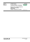
The setup and installation of the Hand-Held Programmer is easy. The Hand-Held
Programmer connects to a Series 90-30, 90-20, or Micro Programmable Logic Controller
through a cable attachment. The cable (catalog number IC693CBL303, 6 feet (2 meters)
long) attaches to both the Hand-Held Programmer and the programmable controller
through a latching connector (one on each end of the cable).
Power is supplied to the Hand-Held Programmer from the PLC through a connection in
the cable. The cable connection also provides an indication to the PLC that a Hand-Held
Programmer is attached as the programming device rather then a different programmer,
since this is the same connection for the Logicmaster 90-30/20/Micro programmer.
ÎÎÎ
ÎÎÎ
ÎÎÎ
ÎÎÎ
ÎÎÎ
a43107
Hand-held
Programmer
ÎÎ
ÎÎ
ÎÎ
ÎÎ
Î
ÎÎ
ÎÎ
ÎÎ
Î
ÎÎ
ÎÎ
ÎÎ
ÎÎ
Î
ÎÎ
ÎÎ
ÎÎ
Î
ÎÎ
ÎÎÎ
Î
Î
ÎÎ
ÎÎ
ÎÎ
ÎÎ
Î
ÎÎ
ÎÎ
ÎÎ
Î
ÎÎ
Î
Î
ÎÎ
ÎÎ
ÎÎ
ÎÎ
ÎÎ
Î
ÎÎÎ
ÎÎÎ
Î
ÎÎ
Î
Î
ÎÎ
ÎÎÎ
Series 90–30 PLC
Cable
(IC693CBL303)
C
P
U
Figure 2-1. Hand-Held Programmer Connection to a Series 90-30 PLC
ÎÎÎ
ÎÎ
ÎÎÎ
ÎÎ
ÎÎÎ
ÎÎÎ
ÎÎÎ
a44549
Series 90–20 PLC
ÎÎ
ÎÎÎÎ
Hand-held
Programmer
Cable (IC693CBL303)
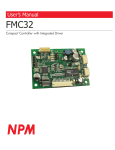
Figure 2-2. Hand-Held Programmer Connection to a Series 90-20 PLC
a45438
Hand-held
Programmer
(IC693PRG300)
Series 90
Micro PLC
Cable (IC693CBL303)
Figure 2-3. Hand-Held Programmer Cable Connection to a Series 90 Micro PLC
GFK-0402G
2-1
2
Powering up the Hand-Held Programmer
The Hand-Held Programmer may be connected to a programmable logic controller
which is powered up, or it may be connected prior to power-up. When connected
during power-up, the Hand-Held Programmer momentarily displays the following
messages on the screen if no power-up diagnostic problems are found.
ROM CHECK OK
RAM CHECK OK
Following this momentary display, the screen will display CONFIGURING SYSTEM. The
amount of time this is displayed can be as long as 7 seconds if there are intelligent
modules plugged into the I/O slots. The initial screen displayed depends upon what
was last displayed when the Hand-Held Programmer was powered down. If the last
display was a data table in data mode, that same data table will be the first screen
displayed when power is restored. If any other display in a different mode was
displayed, the Mode Selection screen will be displayed when the Hand-Held
Programmer is powered up again.
The following example shows the Hand-Held Programmer screen viewing the register
(%R) table in timer/counter display format in data mode, with %R4 as the top reference
displayed, when the unit was powered down.
T/C R0004 0 0
0
0
<R
The same display returns after restoring power.
In the next example, the Hand-Held Programmer was viewing instruction step #0015 in
program mode when the system was powered down.
#0015
<R
LD NOT S0001
In this case, the mode selection screen is displayed after restoring power.
_ 1. PROGRAM
2. DATA
<R
Disconnecting the Hand-Held Programmer
The Hand-Held Programmer can be disconnected from the PLC while power is still
applied. If this occurs in the middle of a modification operation, such as inserting a new
logic instruction step, the operation is automatically canceled. The protection access
level will be set to its default state. Refer to chapter 7, PLC Control and Status, for more
information on password protection.
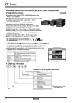
Keypad
The keypad consists of 42 keys, arranged as a matrix of six keys across by seven keys
down, as shown in the following illustration.
2-2
Hand-Held Programmer for Series 90-30/20/Micro Programmable Controllers User’s Manual – February 1996
GFK-0402G
2
a43047
GE Fanuc
SERIES 90–30
PROGRAMMABLE
CONTROLLER
HAND HELD PROGRAMMER
LD
D
OUT
SETM
RSTM
TMR
OUTM
SET
RST
ONDTR
E
AND
A
42-KEY
KEYPAD
I
F
OR
B
Q
UPCTR
NOT
C
MODE
BLK
M
G
AI
AQ
T
S
7
8
9
R
4
5
6
WRITE
1
2
3
DNCTR
RUN
FUNC
DEL
#
SRCH
INS
READ
HEX
0
DEC
VRFY
CLR
ENT
Figure 2-4. Hand-Held Programmer Keypad
The keypad on the Hand-Held Programmer is color-coded for easier identification of the
different keys. Becoming familiar with the programmer keys and their functions will
increase your programming efficiency.
Note
Several keys provide access to two instructions. To access the instruction
printed on the lower half of the key, press the key twice.
GFK-0402G
Chapter 2 Operation
2-3
2
Edit and Display Control Keys
The blue Edit and Display Control keys are located on the right side of the keypad. The
CLR key is red. A description of these keys is provided in the following table:
Table 2-1. Edit and Display Control Keys
Key
MODE
RUN
Description
Select an HHP operating mode.
Start or stop the PLC.
Delete an instruction step in program mode.
DEL
Delete configuration of currently displayed slot in I/O configuration mode.
Delete password at specified access level in protection mode.
SRCH
INS
Search for a given target or initiate a program check in program mode.
Begin an instruction step insertion operation in program mode.
Move between instruction steps in program mode.
Move view window around currently displayed table in data mode.
Select an I/O slot for viewing in configuration mode.
Enter a lower or higher access level in protection mode.
Move between function parameters in program mode.
Invoke or abort a reference table contents change in data mode.
Display a different PLC parameter, or position different binary bit for change in
PLC configuration mode.
Display a different module parameter or field in I/O configuration mode.
Display password for lower or higher access level; view/modify OEM key in
protection mode.
Move between subroutines when in Subroutine Declaration mode.
2-4
ENT
Complete an operation or user input.
CLR
Abort or cancel the current operation or user input.
Hand-Held Programmer for Series 90-30/20/Micro Programmable Controllers User’s Manual – February 1996
GFK-0402G
2
Ladder Logic Keys
The gray Ladder Logic keys are located on the upper portion of the keypad. These keys
are used to enter the program elements that make up the user’s program. A description
of these keys is provided in the following table:
Table 2-2. Ladder Logic Keys
Key
LD
D
AND
Description
OUT
SETM
RSTM
OUTM
SET
RST
Program a boolean logic instruction in program mode.
F
E
OR
NOT
BLK
FUNC
Program a function or function block instruction in program mode.
Program TMR, ONDTR, UPCTR, DNCTR function blocks in program mode.
TMR
UPCTR
ONDTR
DNCTR
A I
BQ
CM
AI
AQ
T
G
S
R
A I
BQ
CM
AI
AQ
T
D
AND
F
E
OR
NOT
Change data mode display format to timer/counter; automatically select
register table if not displayed in data mode. (This does not apply to the
FUNC key.)
Specify a memory reference type in program and data mode.
I/AIandQ/AQ and G specify module types in configuration mode.
Specify a binary, decimal (possible signed) or hexadecimal value in program
and data mode.
Specify a slot number, reference address, point count or PLC parameter
value; value format may be either binary, signed decimal, or hexadecimalin
configuration mode.
Specify the alpha characters of a 1 - 4 digit hexadecimalpasswordvalue.
Specify an instruction step in program mode.
#
Override, or cancel the override on, a discrete reference in data mode.
Indicate a new rack/slot number (GOTO) in configuration mode.
Zoom into or out of subroutine logic.
GFK-0402G
Chapter 2 Operation
2-5
2
Numeric Keys
The white Numeric keys are located on the lower left side of the keypad. They include
the keys for the numerals 0 through 9, the –/+ key, and the HEX/DEC key. A
description of these keys is provided in the following table:
Table 2-3. Numeric Keys
Key
Description
0
1
2
3
Specify a binary, decimal (possible signed), or hexadecimal value in
program and data mode.
4
5
6
7
Specify a slot number, reference address, point count, or PLC parameter
value; value format may be either binary, signed decimal, or hexadecimal in configuration mode.
8
9
–+
Specify a 1 - 4 digit hexadecimal password value in protection mode.
Specify a binary, decimal (possible signed), or hexadecimal value in
program and data mode.
Toggle PLC configuration parameter setting in configuration mode.
Toggle between run and stop mode in any mode.
Specify a signed decimal or hexadecimal constant in program mode.
HEX
Change display format between binary, signed decimal, and hexadecimal
in data mode.
DEC
Change display format between decimal, hexadecimal, and 8-bit binary in
configurationmode.
Program Transfer Keys
The Program Transfer keys are located in the blue shaded area in the lower right portion
of the keypad. They include the READ/VERIFY and WRITE keys.
Table 2-4. Program Transfer Keys
Key
READ
VRFY
Description
Read or verify the memory card or system EEPROM in program mode.
Read configuration of module currently installed in slot.
WRITE
2-6
Write the memory card or system EEPROM in program mode.
Hand-Held Programmer for Series 90-30/20/Micro Programmable Controllers User’s Manual – February 1996
GFK-0402G
2
Power-Up Key Sequences
The key sequences listed below can be used during power-up to provide additional start-up
instructions for the PLC, or to override the previous configuration. When used to override
the previous configuration these keys must be depressed simultaneously while the ROM
CHECK OK & RAM CHECK OK screen is being displayed and held depressed until the
mode screen is displayed on the HHP. (The keys must be pressed simultaneously until the
ROM CHECK OK, RAM CHECK OK message is removed from the screen.)
During power-up, the PLC may be instructed to totally clear all data stored within it. This
includes program logic, data tables, configuration, passwords, and the OEM key. To do this,
press and hold the CLR and M/T keys simultaneously while the PLC is powering up. A
ROM CHECK OK or RAM CHECK OK message is displayed on the Hand-Held
Programmer screen upon receiving power. Double key strokes must be held until after the
ROM CHECK OK and RAM CHECK OK message is cleared. Note that power-up sequences
from the HHP are not processed for warm start powerups.
Caution
Do not press the CLR and M/T keys to clear memory if an OEM program
is in RAM memory. All configuration data and logic will be lost.
The PLC can be configured to download a logic program during start-up from EEPROM
(located in the EEPROM socket on the baseplate of the Model 311 and in the CPU module
in a Model 331) to RAM, instead of running from the existing program in RAM. You can
override this option when testing changes to the program so that the program in RAM is
retained, and not overwritten by the program in EEPROM. To use RAM memory
regardless of the configuration, press LD and NOT keys simultaneously while the PLC is
powering up.
The PLC can be configured to power up in RUN or STOP mode, or in the same mode it
was powered down in. This configured state can be overridden to ensure that the PLC will
power up in STOP mode, regardless of the configuration. To do this, press NOT and RUN
simultaneously during power-up until the RAM CHECK OK, ROM CHECK OK message is
displayed on the screen.
Table 2-5. Power-Up Options
Key Sequence
CLR
CM
T
F
LD
NOT
NOT
RUN
F
GFK-0402G
Chapter 2 Operation
Description
Totally clears all data stored within the PLC, including program logic, data
tables, configuration, passwords, and the OEM key. Do not use this function if an OEM program is in RAM memory, as all configuration data and
logic will be lost.
Prevents the PLC during power-up from downloading a program from EEPROM to RAM and puts the CPU in the STOP mode. Use RAM
memory regardless of the configuration.
Ensures that the PLC powers up in the STOP mode.
2-7
2
Special Key Sequences
Table 2-6. Special Key Sequences
Key Sequence
#
SRCH
– +
9
Description
9
9
DEL
#
– +
1
Clear all program logic instruction steps from memory without affecting
any other memory, such as data or configuration (only when in program
mode, will not work in program insert mode).
Begin the program check function (only when in program mode, will not
work when in program insert mode).
ENT
Selecting an Operating Mode
In general, most functions are available only in a single mode of operation. To interact
with a particular function, the correct mode of operation must first be selected.
1.
Press the MODE key to select a new mode of operation. After pressing MODE, the
following initial screen will be displayed:
_ 1. PROGRAM
2. DATA
2.
Use the Up and Down cursor keys to scroll the menu selection display in order to
view other possible selections. Each press of the Up cursor key scrolls the menu up
one position; each press of the Down cursor key scrolls the menu down one
position. Possible selections include:
1.
2.
3.
4.
2-8
<S
PROGRAM
DATA
PROTECT
CONFIG
3.
To select an operating mode, enter the single digit corresponding to the desired
mode. The name of that mode does not have to be currently displayed on the menu
display in order for that mode to be selected.
4.
Press the ENT key to invoke the new mode.
5.
One alternate method of selecting the operating mode is to use the Up and Down
cursor keys to display the desired mode at the top of the screen and press the ENT
key to execute the selection. If the desired mode is already displayed at the top of
Hand-Held Programmer for Series 90-30/20/Micro Programmable Controllers User’s Manual – February 1996
GFK-0402G
2
the screen, simply press the ENT key. Pressing the ENT key with no mode value
entered will execute the current top menu selection.
Modes 1, 2, 3, and 4 are currently the only modes supported. If any other number is
entered on the mode selection screen, it will be ignored.
To cancel a mode change request, press the CLR key or press the desired new number.
Read/Write/V erify Functions
Support is provided for the storage of data in a secondary storage device. The secondary
storage device may be either an EEPROM installed in the PLC backplane or a Series 90
Memory Card inserted into the Hand-Held Programmer. For either secondary storage
device, the following PLC data is always stored:
D
D
D
D
D
Program logic Statement List instructions.
Registers.
Slot configuration data.
Passwords.
OEM key.
Functionality is provided for writing, reading, and verifying this data with either an
EEPROM or Series 90 Memory Card. This functionality is available only in program
mode, when the PLC is stopped and not scanning I/O.
Series 90-30 CPU models 340, 341, and 351, and the Series 90 Micro PLC can have data
written to flash memory. During a write to flash, there is no in progress indication. Other
CPU models, that use EEPROM as a storage device, do have an in progress indication
during a write operation.
Starting/Stopping the PLC
The PLC may be started or stopped while in the Mode Selection screen, or in any of the
four major operating modes (program, data, protection, or configuration).
Selecting RUN/STOP Mode from Mode Selection Screen
The initial mode selection screen indicates that the PLC sweep is in the STOP mode as
shown by the <S in the upper right corner of the display screen.
_ 1. PROGRAM
2. DATA
Initial display:
<S
To select the RUN mode:
Press the
RUN
key:
PRESS <–/+>KEY <S
After exiting the RUN/STOP Sweep Mode function, the HHP will return you to the
Mode Select menu.
GFK-0402G
Chapter 2 Operation
2-9
2
Selecting RUN/STOP Mode from an Operating Mode
Before the PLC’s operating state may be changed, a minimum access level of 2 must first
be selected. If the access privilege is only level 1, the change mode request will be
refused and a PROTECT error message will be displayed. See Chapter 7 for more
information on PROTECTION.
Before the PLC’s operating state is changed from stopped to running, the program is
first checked to ensure that no syntax errors exist in the program. If an error is found,
the request to execute the program is refused and an indication of the problem is
displayed by an error message. By exiting the start/stop function and entering program
mode if not already in that mode, you may view the instruction step containing the
error. It is possible that the program may contain multiple errors; but only the first error
detected, beginning with the start of the program, is displayed.
When making a mode change from STOP to RUN the following screen may be
displayed:
CLEAR FAULTS? <S
<ENT>=Y <CLR>=N
This indicates that there is a fault in the CPU. Check the fault indicator system tables SA,
SB, and SC. A fatal fault will not allow you to proceed into the run mode until it is
removed and cleared. A diagnostic fault must be cleared. To clear faults, press the ENT
key again. Press the CLR key to return to the stop mode and check tables for faults.
A change in the PLC operating state is first initiated by pressing the RUN key. The
desired state, run mode or stop mode, is then selected. The –/+ key is used to toggle
between the run mode and stop mode states. Pressing the –/+ key initially selects run
mode; pressing the –/+ key again toggles the selection to stop mode. Each time you
press the –/+ key, the mode is toggled. When the desired operating mode is displayed
on the screen, press the ENT key.
In the following example, the current operating state of the PLC in the configuration
mode is changed from run mode to stop mode.
1.
If protect mode is selected, the initial display screen would appear as:
LEVEL3
<R
This screen indicates that the PLC is running (executing) a program, as shown by the
<R in the PLC state field (upper right corner) of the display screen.
2.
Press the RUN key to initiate a change in the PLC operating state:
PRESS <+/–>KEY <R
3.
Press the –/+ key to initially select run mode:
RUN MODE
2-10
<R
Hand-Held Programmer for Series 90-30/20/Micro Programmable Controllers User’s Manual – February 1996
GFK-0402G
2
4.
Press the –/+ key again to toggle the selection to stop mode:
STOP MODE
<R
Each time the user presses the [–/+] key, the mode is toggled. When the desired
operating mode is displayed on the screen, the user initiates the change by pressing
the [ENT] key.
5.
Then, press the ENT key:
LEVEL3
<S
This screen indicates that the PLC is now stopped, as indicated by the <S in the PLC
state field of the display screen.
Canceling a Mode Change
The CLR key may be used to cancel an operating mode change before activating it.
Press the CLR key twice to exit from the mode change screen and return to the currently
entered function.
User PROM Option
Application programs are normally developed in the CPU’s RAM memory and executed
from RAM memory. If additional program integrity is desired, or operation of the PLC
without a battery is desired, an optional EEPROM or EPROM can be installed in a spare
socket (labeled PROGRAM PROM) on the Model 311 backplane or in a socket on the
Model 331 CPU module. EEPROMs can be written to and read from. EPROMS can be
read when installed in the PLC, however they must be written to using an external
PROM burning device. Non-removable flash memory performs this function on the
Model 340, 341, and 351 CPUs.
A typical scheme for using these devices is to develop programs using an EEPROM.
When the program in RAM has been developed and debugged, it is saved to EEPROM.
The EEPROM can then be removed from the PLC and used as a master to make backup
or multiple copies of the program to EPROM memory. The EPROM can then be
installed in the socket provided in the CPU and used as a non-volatile memory for
battery-less operation, or to run the same program in multiple PLCs. The Model 331 CPU
has a jumper (JP1) located next to the EEPROM/EPROM socket to let you select between
EEPROM or EPROM.
Jumper
3-2
2-1
Selects
EEPROM
EPROM
When the EEPROM or EPROM is installed, the application program stored in the device
is automatically loaded into RAM memory whenever the CPU is powered-up. However,
this only happens, if EEPROM is selected as the Program Source parameter during
configuration with the Hand-Held Programmer or Logicmaster 90 configuration
software.
GFK-0402G
Chapter 2 Operation
2-11
2
Caution
If EEPROM is selected and a PROM is not in the socket or a blank
PROM is in the socket, on a power-up cycle a blank program will be
placed into the RAM memory, therefore the program in RAM will be lost.
EEPROM and EPROM memory chips are available from GE Fanuc. Catalog numbers for
these devices are listed in the following table.
Table 2-7. EEPROM and EPROM Memory Catalog Numbers
GE Fanuc
PROM
Part Number
Third Party Source
Vendor
Part Number
Catalog Number
Description
IC693ACC305 (Qty 4)
28C256 EEPROM, 350ns
44A725999-000
XICOR
XICOR
X28C256P or
X28C256-25
IC693ACC306 (Qty 4)
32Kx8 UV EPROM, 150ns
44A723379-000
NEC
PD27C256AD-15
Atmel
AT27C256-15DC1
Toshiba
TC57256AD-15
Hitachi
HN27C256AG-15
AMD
AM27C256-150DC
Intel
TD27C256A-1
Installing a Blank EEPROM/EPROM
Use the following procedure for installing a blank EEPROM or EPROM in a Series 90-30
or Series 90-20 PLC.
Caution
You must be careful when installing a blank EEPROM or EPROM in
the PROM socket of the CPU in a Series 90-30 or Series 90-20 or the
program in RAM memory will be lost.
1.
Configure the CPU to
PRG SRC RAM
and
REG SRC RAM
(see NOTE at end of this procedure)
2-12
2.
Remove power from the PLC.
3.
Remove the CPU from its socket on the baseplate.
4.
Remove the faceplate and LED lens cover from the CPU. The PROM socket is now
accessible at the bottom of the CPU board.
5.
Turn the screw at the center top of the socket counter clockwise so that the slot lines
up with the O. This allows an EEPROM or EPROM to be inserted.
Hand-Held Programmer for Series 90-30/20/Micro Programmable Controllers User’s Manual – February 1996
GFK-0402G
2
6.
Insert the EEPROM or PROM into the socket with the notch facing the screw.
7.
Turn the screw clockwise so that the slot lines up with the C. The EEPROM or
EPROM is now locked into the socket.
8.
Set the jumper plug at the bottom of the socket for EEPROM (3-2) or PROM (2-1), as
required.
9.
Replace the faceplate.
10. Insert the CPU into its connector in the baseplate.
11. Turn-on power to the PLC.
12. The CPU can now be configured to
PRG SRC EEPROM
and
REG SRC EEPROM
Note
If not configured for Program (PRG) and Register (REG) from RAM
when power is applied after a blank EEPROM is inserted, the contents
of the blank PROM will be loaded into the RAM memory. The CPU can
be forced to load Program and Registers from RAM, if on power-up
using the Hand-Held Programmer the LD and NOT keys are depressed
simultaneously and held depressed during power-up until the MODE
selection menu is displayed.
Series 90 Memory Card
In addition to EEPROM a Series 90 Memory Card inserted into the Hand-Held Programmer
may be used to save, retrieve or verify program logic data and configuration data contained
on it versus the actual PLC contents. The Series 90 Memory Card is not supported by the
Model 351 CPU.
If the memory card or EEPROM has not been properly inserted before attempting a write,
read, or verify operation, the absence of the card or EEPROM will be detected as an error
and an error message will be displayed.
The PLC must also be stopped and must not be scanning I/O before you can perform a
memory card or EEPROM operation. If you attempt to write, read, or verify data when the
PLC is running, a RUNNING error message will be displayed on the screen. You must first
stop the PLC before attempting the desired operation again. Also, when the CPU is
configured for DO I/O, a DO I/O error message will be displayed on the screen. Change the
CPU configuration STOP MD DO I/O to STOP MD NO I/O.
It is possible that a communications error between the Hand-Held Programmer and the
memory card may occur during a write, read, or verify operation. If this occurs, the
operation will be canceled and a COMM ER error message will be displayed. Make sure
that the memory card is properly seated in the Hand-Held Programmer slot, before
attempting the operation again.
The following screen format is used to write, read, or verify the memory card or EEPROM.
Table 2-8. Read/Write/V erify Series 90 Memory Card or EEPROM
Operation
Device
<S
Device Address
GFK-0402G
Chapter 2 Operation
2-13
2
Operation:
The operation field indicates the particular operation which is to be performed on the
destination device, MEM CARD or EEPROM. Its modes of operation are listed below,
along with a description of each.
MODE OF OPERATION
—————————————————
READ
WRITE
VERIFY
DESCRIPTION
————————————————————————————————————————————————————————
Read the contents of the memory card or EEPROM into RAM.
Write the contents of RAM to the memory card or EEPROM.
Verify contents of the memory card or EEPROM with RAM.
Device:
This field identifies the destination device, which in this case, is the Series 90
Memory Card or EEPROM. This field may also function as an error
message window if you attempt a read, write, or verify operation without a
memory card or EEPROM properly inserted.
<S:
<S indicates that the PLC is currently stopped. The PLC must be in STOP
NO I/O before you can perform a read, write, or verify operation. <R
displayed in this field would indicate that the PLC is currently running
(executing a program). If you attempt an operation with the PLC running
or in STOP DO I/O, an error message is displayed on the screen and the
operation will not be performed.
Device Address: This number is continuously updated while the device is being
read/written to indicate that the operation is in progress.
Loading RAM from the Memory Card or EEPROM
To read (load) the contents of a previously programmed Series 90 Memory Card or
EEPROM into RAM memory, follow this procedure:
1.
In program mode, press the READ/VERIFY key:
READ MEM CARD <S
If EEPROM is desired, press the –/+ key to toggle the selection to EEPROM.
2.
Then, press the ENT key twice to complete the read operation (see Reading Program
Logic Only for selective read). The above screen will be displayed while the transfer
is taking place. This time is approximately 1:35 (one minute, 35 seconds) for an OK
program in a Model 311.
READ OK
2-14
<S
Hand-Held Programmer for Series 90-30/20/Micro Programmable Controllers User’s Manual – February 1996
GFK-0402G
2
Storing RAM to the Memory Card or EEPROM
To store (write) a copy of the contents of RAM memory into a Series 90 Memory Card or
EEPROM, follow this procedure: (Note: for the Model 340 or 341, use steps 1, 2, an 3; for all
other models use only steps 1 and 3)
1.
In program mode, press the WRITE key:
WRITE MEM CARD <S
If EEPROM is desired, press the –/+ key to toggle the selection to EEPROM.
2.
Then, in the Model 340 or 341, press the ENT key to choose the number of registers to save
(either 9999 or 2048). The second line of the display will read:
REGS TO SAVE: 9999
To save 2048 registers instead, press the –/+ key to toggle the selection to 2048.
3.
For all models, press the ENT key to complete the write operation. The above screen
will be displayed while the transfer is taking place. This time is approximately 1:35
(one minute, 35 seconds) for an OK program in a Model 311.
WRITE OK
<S
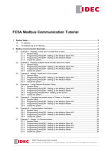
In order to write data, the memory card must not be write-protected (through the tab on
the card). If it is write protected when a write operation is requested, the write protect
will be detected and the request refused. A PROTECT error message will be displayed
on the screen. Remove the write protect condition from the Series 90 Memory Card
before attempting another programming operation.
ÎÎ
ÎÎ
ACTUAL SIZE (END VIEW)
Î
Î
ACTUAL SIZE (TOP VIEW)
a45055
WRITE PROTECT SCREW
(PROTECTED)
ÎÎ
Î
WRITE PROTECT SCREW
(UNPROTECTED)
GE Fanuc
Figure 2-5. EEPROM Memory Card (Catalog Number IC693ACC303)
GFK-0402G
Chapter 2 Operation
2-15
2
Verifying RAM with the Memory Card or EEPROM
To manually verify the contents of a previously programmed Series 90 Memory Card or
EEPROM with the PLC’s RAM memory, follow this procedure:
1.
In program mode, press the READ/VERIFY key twice:
VERIFY MEM CARD <S
If EEPROM is desired, press the –/+ key to toggle the selection to MEM CARD or
EEPROM.
2.
Then, press the ENT key twice to complete the verify operation (see Reading Program
Logic Only for selective read):
VERIFY OK
<S
Error Messages During EEPROM/MEM Card Operation
The following error messages may occur during EEPROM/MEM card operations.
NO PRIV: Current privilege level of the PLC is too low for the intended operation
(see Chapter 7).
NO CARD: No memory card is inserted in the Hand-Held Programmer, or the
inserted card has insufficient capacity for the operation.
CFG ERR: The I/O configuration saved in the memory card is incompatible with the
target PLC (for example, EEPROM has a PCM configured and the target
PLC is 311/211).
ROM ERR: No EEPROM installed or EEPROM data has been corrupted or never
been written.
COMM ERR: The PLC model number saved on the device cannot be read into the
PLC or a data error occurred while reading a memory card.
PROTECT: The memory card is write protected.
VRFY ERR: The data in the device does not exactly match the data in PLC RAM.
PSW ERR: An attempt was made to read a configuration enabling passwords into a
PLC with passwords disabled or with an active password.
PRG ERR: The program saved in the device cannot be read into this PLC (for
example, the saved program reference is %R2000 and target PLC is a model
311 or 211).
DO I/O: CPU is configured for STOP MD DO I/O reconfigure the CPU for STOP MD
NO I/O.
2-16
Hand-Held Programmer for Series 90-30/20/Micro Programmable Controllers User’s Manual – February 1996
GFK-0402G
2
Program/Configuration Portability
Programs, configuration, and registers can be transported from one model to a different
model of a Series 90-30 or Series 90-20 CPU. This can be done using either an EEPROM,
a MEM card, or a UVEPROM (if copied from an EEPROM). In this discussion these
devices will be referred to as the device, since all of the rules apply equally to all three.
The model of the CPU from which the device was written is referred to as the source
CPU. The model of the CPU into which the contents of the device will be read is
referred to as the target CPU.
There are certain restrictions on this portability as listed below:
1.
Programs must be compatible with the target CPU. That is, they must not have
references to addresses which do not exist in the target CPU and they must fit into
the size restrictions of the target CPU. If non-valid references are attempted and this
error is detected by the PLC, a PRG ERR message will be reported to the user by the
HHP.
2.
Configurations must be compatible with the target CPU. That is, they must not
contain modules not supported by the target CPU nor have modules in racks not
supported by the target CPU. If this error is detected by the PLC, then a CFG ERR
message will be reported to the user by the HHP.
3.
When reading configurations from a model which supports more slots into a CPU
which supports fewer slots, the slots higher then those supported by the target CPU
must be EMPTY.
4.
When reading configurations from a model which supports fewer slots into a CPU
which supports more slots, the slots in the target CPU beyond those supported by
the source CPU will be set to EMPTY.
5.
When reading registers from a CPU which supports a different number of registers
then the target CPU, those registers higher then those supported by the smaller CPU
will be ignored.
6.
When configuration is read from one CPU model into a different model, the PLC
must change the CPU model in the configuration to match the target model. After
this configuration has been read and the model changed, the contents of the
configuration in RAM memory cannot be verified with the contents of the
configuration on the device.
7.
The Model 351 CPU does not support the Series 90 Memory Card and its flash
memory is not removeable. Transporting programs to and from Model 351 CPUs is
done using Logicmaster -30/20/Micro software. With this exception, the following
discussions on reading the device also apply to reading data from the Model 351 flash memory.
A list of the error messages which can be produced as a result of attempting to read a
device can be found in Chapter 9 in this manual along with a description of possible
causes and corrective actions.
If the entire contents of the device are not read, then the data which was not read
remains intact within the PLC. For example, if only the program is being read, then the
configuration and registers will remain unchanged by the attempted read, regardless of
any errors encountered while reading the program.
Examples of program/configuration compatibility operations with the HHP are shown
on the following pages.
GFK-0402G
Chapter 2 Operation
2-17
2
Reading the entire device
To read (load) the entire contents of an EEPROM previously programmed from the same
CPU model follow this procedure:
In PROGRAM mode, press the
READ
VRFY
key:
READ MEM CARD <S
To select which items will be read:
Press the
ENT
key:
READ MEM CARD <S
PRG CFG REG
To read the logic program, configuration, and registers saved on the card:
Press the
ENT
key:
READ MEM CARD <S
PRG CFG REG xxxx
The address at the end of the lower line will be continually updated as the read
operation progresses.
If the read is completed successfully, the HHP will display:
READ OK
<S
If an error is encountered during the read operation, an error message will be displayed,
for example:
READ PRG ERR
<S
If a program error is read, the contents of the PLC will be cleared (program,
configuration, and registers).
2-18
Hand-Held Programmer for Series 90-30/20/Micro Programmable Controllers User’s Manual – February 1996
GFK-0402G
2
Reading Program Logic Only
If desired, you can read only the program logic from the device, ignoring the
configuration and register data which was saved on the device. To do this use the
following procedure:
In PROGRAM mode, press the
READ
VRFY
key:
READ MEM CARD <S
To select which items will be read:
Press the
ENT
key:
READ MEM CARD <S
PRG CFG REG
To read only the program logic:
Press the
– +
key:
READ MEM CARD <S
PRG
Each time that you press the –/+ key allows the selection of other combinations of
program, configuration, and/or registers which will be read from the device. All possible
combinations or these three data types can be read. When the lower line of the display
contains the desired combination to be read:
Press the
ENT
key:
READ MEM CARD <S
PRG
xxxx
Note that the address displayed at the end of the lower line will be continually updated
as the read operation progresses.
If the read is completed successfully, the HHP will display:
READ OK
<S
If an error is detected during the read operation, an error message will be displayed, for
example:
READ PRG ERR
GFK-0402G
Chapter 2 Operation
<S
2-19
2
If an error is detected, the contents of the PLC logic program will be cleared. If the
attempt had been to read more then one type of data (for example, program and
registers), then each of those types of data would have been cleared upon detection of
an error.
Differing CPU Models
If the CPU model of the source PLC is not the same as the CPU model of the target CPU,
then the model must be changed when the configuration is read from the device. For
example, the device may have been written using a Series 90-20 model 211 CPU and the
contents of the device are being read into a Series 90-30 model 311 CPU. This changing
of the CPU model type applies ONLY when reading configuration.
To read the contents of a device from a different CPU model, use the following steps:
In PROGRAM mode, press the
Press the
– +
READ
VRFY
key:
key:
READ MEM CARD <S
READ EEPROM
<S
READ EEPROM
PRG CFG REG
<S
To select which items will be read:
Press the
ENT
key:
To read the logic program, configuration, and registers saved on the card:
Press the
ENT
key:
READ EEPROM
<S
PRG CFG REG xxxx
The address at the end of the lower line will be continually updated as the read
operation progresses. If the read is completed successfully, the HHP will display:
CHANGE MODEL? <S
<CLR>=N <ENT>=Y
2-20
Hand-Held Programmer for Series 90-30/20/Micro Programmable Controllers User’s Manual – February 1996
GFK-0402G
2
To change the model of the configuration being read into the PLC (the device contents
will be unaffected):
ENT
Press the
READ OK
key:
<S
If you do not want to change the model number of the new configuration (thereby
rejecting the data and aborting the read), use this step:
Press the
CLR
READ ABORTED
key:
<S
If the read operation is aborted, the contents of the memory areas in the PLC which
were being read from the device will be cleared. For example, if program and
configuration is being read and you elect to not change the model number, both the
program and configuration will be cleared.
EEPROM Source at Power-Up
If the EEPROM is chosen as the program source during the power-up sequence, then the
contents of the EEPROM will be rejected in its entirety if the EEPROM configuration is
not compatible with the CPU model in which it is installed. The EEPROM used as a
program source during power-up MUST have been written by a CPU of the same model.
If the models differ, or if the configuration is incompatible with the CPU in which it is
installed, the program, configuration, and registers in RAM memory will be cleared and
the PLC will power up in STOP mode. If this happens, a fatal fault will be generated.
Before Power Cycle
After Power Cycle
Configuration of Program Source CPU
Configuration of Program Source CPU
RAM
EEPROM
RAM
CPU will run with
program that was in
EEPROM
RAM
RAM
RAM
RAM
RAM
EEPROM
RAM
RAM
RAM
EEPROM
EEPROM
EEPROM
EEPROM
EEPROM
EEPROM
RAM
EEPROM
EEPROM
EEPROM
EEPROM
EEPROM
Blank EEPROM present
RAM
-
Blank
EEPROM
No EEPROM present
RAM
-
Blank, no program
GFK-0402G
Chapter 2 Operation
2-21
Chapter
3
3 Series 90-30/20 PLC Configuration
section level 1 1
figure bi level 1
table_big level 1
A number of PLC parameters are user-configurable. Each of these parameters has a
default value which, for many users, will not need to be changed. These parameters,
their selections and default selections are shown in the following table.
Note
This chapter describes configuration for the Series 90-30 and 90-20 PLCs.
See Chapter 4 for configuration information for the Micro PLC.
Table 3-1. User-Configurable PLC Parameters
Parameter
GFK-0402G
Selections
Default Value
Key click
ON (ENABLED)
OFF (DISABLED)
OFF
Time of day clock
(Not available on Model 311/321,
Model 313/323, or Model 211)
Month
Day
Year
Hour
Minute
Second
Programsource
RAM
EEPROM
RAM
Registersource
RAM
EEPROM
RAM
Power-up mode
RUN
STOP
SAME PD
SAME PD
Active Constant Sweep Mode
DISABLE
ENABLE
DISABLE
Active Constant Sweep Setting
5 - 200 msec
100 msec
Configured Constant Sweep Mode
DISABLE
ENABLE
DISABLE
Configured Constant Sweep Setting
5 - 200 msec
100 msec
I/O scan in stop mode
NOI/O
DOI/O
NOI/O
Dual use checking
SINGLE
WRN MUL
MULT
SINGLE
Port idle time
1 - 60 seconds
10 seconds
3-1
3
Table 3-1. User-Configurable PLC Parameters (continued)
Parameter
Selections
Default Value
Baud rate
300
600
1200
2400
4800
9600
19.2k
19.2k
Data bits
7 BITS
8 BITS
8 BITS
Stop bits
1 BIT
2 BITS
1 BIT
Parity
ODD
NONE
EVEN
ODD
Modem turnaround time
0 to 255 counts
0
Disablepasswords
ENABLE
DISABLE
ENABLE
CPU ID
6 ASCII characters 0 - F
000000
DefaultI/OConfiguration
ENABLE
DISABLE
ENABLE
Checksum Words Per Sweep
8 through 32
8
This chapter describes how each parameter is configured.
The initial screen displayed in configuration mode is the last one viewed the previous
time configuration mode was selected, since the PLC was powered up. If this is the first
time configuration mode was entered, slot 1 of rack 0 (Model 331/340/341/351 CPU rack)
or slot 0 of rack 0 (Model 311/313) is displayed.
Entering Configuration Mode
In order to view and/or change the PLC parameters, you must first select the
configuration mode of operation.
1.
To select configuration mode, press the MODE key to display the operating mode
selections.
_ 1. PROGRAM
2. DATA
2.
Press the 4 key to select configuration mode.
4_ 1. PROGRAM
2. DATA
3-2
<S
<S
Hand-Held Programmer for Series 90-30/20/Micro Programmable Controllers User’s Manual – February 1996
GFK-0402G
3
3.
Press the ENT key to enter the new mode.
The first screen displayed will be R0:00 for Model 311/321 and 313/323 or R0:0l for Model
331/340/341/351 and Model 211 (Model 211 is Series 90-20). This is the first PLC
configuration screen displayed. Use the z ‡ keys to view the other parameters and
the –/+ key to select the variable for a parameter.
R0:00 PLC
<S
KEY CLK: OFF
Keypad Functionality
The following table gives an overview of how the keypad on the Hand-Held
Programmer is used in PLC configuration mode.
Table 3-2. Keypad Functionality in PLC Configuration Mode
Key Group
0-9
I/AI (A)
Q/AQ (B)
Description
Specify a slot number or PLC parameter value; value format can
be either binary, signed decimal, or hexadecimal. (A)....(F) - these
keys are used for entering hexadecimaldigitsA....F.
M/T(C)
AND (D)
OR (E)
NOT (F)
GFK-0402G
HEX/DEC
Change the display format between decimal, hexadecimal,and
8-bit binary.
–/+
Toggle the PLC configuration parameter setting.
CLR
Abort or cancel the current operation or user input.
Up and Down cursor keys
Select an I/O slot for viewing.
Left and Right cursor keys
Display a different PLC parameter, or position different binary bit
for change.
#
Indicate a new rack/slot number (GOTO).
ENT
Complete an operation or user input.
RUN
Start or stop the PLC.
MODE
Select an HHP operating mode.
Chapter 3 Series 90-30/20 PLC Configuration
3-3
3
Display Format
The following screen format is used for configuring the PLC parameters:
Table 3-3. Configuration Screen Format
R
Rack
#
:
Slot
#
Module Type or Message
PLC
State
Parameter Label & Parameter Value
Rack #: Slot #: The rack #: slot # field indicates the currently displayed rack and slot.
For configuration purposes, the model 311 and 313 CPU module is embedded in the backplane. The Model 331/340/341/351 and Model 211
CPU module is always located in slot 1 of rack 0.
Module Type or Message: The module type or message field normally displays the
designation PLC, indicating that PLC parameters are being configured.
This field also functions as an error message window.
PLC State: The PLC state field indicates whether the PLC is currently stopped or is
running (executing a program). A leading < character, followed by S if
the PLC is stopped or R if it is running, indicates the state of the PLC.
Parameter Label: The parameter label field contains a text string which is used as a
prompt to the user for a particular parameter.
Parameter Value: The parameter value field contains a value input by the user.
Locating a Slot or Rack and PLC Parameters
For configuration purposes, the Model 311/321 and 313/323 CPU (slot 0 of rack 0) is
embedded in the backplane. The Model 331/340/341/351 and 211 CPU module is always
located in slot 1 of rack 0.
The Up and Down cursor keys can be used to view the previous or next slot in the rack.
If the current slot is at the end of the current rack, the next slot displayed will be the
adjacent slot in the next/previous rack. For Model 211 slot 2 is always inputs, slot 3 is
always outputs and slot 4 is always High Speed Counter.
The # key, in conjunction with a slot number, can be used to go to a particular slot, as
shown in the following example.
1.
When configuration mode is selected, the first screen displayed is the last slot
viewed the last time this mode was entered (except after power-up). For this
example, assume that slot 3 of the main rack was the last slot viewed:
R0:03 EMPTY
3-4
<S
Hand-Held Programmer for Series 90-30/20/Micro Programmable Controllers User’s Manual – February 1996
GFK-0402G
3
2.
Press the # key to begin the GOTO operation:
R0:03 EMPTY
R_
3.
Enter the number of the rack which contains the slot you want to go to. For this
example, enter a zero (0) for the main rack:
R0:03 EMPTY
R0:_
4.
<S
Then, enter the number of the slot you want to go to. For this example, enter a 1 for
slot 1 of the main rack:
R0:03 EMPTY
R0:1_
5.
<S
<S
Then, press the ENT key. Slot 1 of the main rack is now displayed on the screen:
R0:01 PLC
KEY CLK: OFF
<S
If a rack number greater then the maximum supported by the system is indicated, the
highest numbered rack will be displayed by default.
If a slot number greater then the maximum supported by the rack is entered as part of
the GOTO operation, the greatest numbered slot within the rack will be displayed by
default. For example, if the rack only contains five slots and you attempt to go to slot 9,
slot 5 will be displayed on the screen of the Hand-Held Programmer.
In either case, no error message will be displayed.
Key Click Parameter
When viewing the PLC configuration, the first parameter field encountered is the key
click (KEY CLK) parameter. By default, no audible click is heard when a key is pressed.
You can choose an audible feedback from the keys by enabling this parameter. Use the
–/+ key to toggle the selection between enabled (ON) and disabled (OFF).
Clock Parameter
The models 331, 340, 341, and 351 CPUs support a time-of-day clock. The month, day,
year, hour, minutes, and seconds can be set by the user.
Use the Right cursor key to scroll through the PLC parameters until the clock parameter
is displayed. Then, continue to press the Right cursor key to select each of the clock
parameters, in turn. To change a parameter, enter the new value and press the ENT key.
GFK-0402G
Chapter 3 Series 90-30/20 PLC Configuration
3-5
3
Program Source Parameter
At power-up, you can specify that the program copy in RAM should be used, or that the
program copy in EEPROM should be loaded into RAM and used. This can be helpful
when you are running a program without battery backup.
Use the Right cursor key to scroll through the PLC parameters until the program source
(PRG SRC) parameter is displayed. Then, use the –/+ key to toggle the selection
between RAM and EEPROM. By default, the program copy in RAM will be used.
Register Source Parameter
At power-up, you can specify that the register table (R) values in RAM should be used, or
that the register table initialization values in EEPROM should be loaded into RAM and
used. This is also useful when you are running a program without battery backup.
Use the Right cursor key to scroll through the PLC parameters until the register source
(REG SRC) parameter is displayed. Then, use the –/+ key to toggle the selection
between RAM and EEPROM. By default, the register table copy in RAM will be used.
Note
Setting this parameter to EEPROM has no effect unless Program Source
is also set to EEPROM.
Power-Up Mode Parameter
The PLC can be configured to always power up in one of these modes:
1.
RUN mode.
2.
STOP mode.
3.
The SAME mode Powered Down in (SAME PD).
STOP mode should be used when the program is not fully debugged or requires manual
intervention during start-up. RUN mode, on the other hand, should be used when
manual intervention is neither required nor allowed. The normal selection for this
parameter is to power up in the SAME mode that the system was powered down in.
Use the Right cursor key to scroll through the PLC parameters until the power-up mode
(PU MODE) parameter is displayed. Then, use the –/+ key to toggle the selection
between STOP, RUN, and SAME PD.
By default, the PLC will power up in the SAME PD mode powered down in.
Active Constant Sweep Mode Parameter
The PLC can be configured during RUN mode to use a constant amount of time per
sweep. The active constant sweep mode parameter gives you the ability to enable or
disable the constant sweep mode while the program is running, and have the effects
noticed immediately. This parameter can be used to toggle the sweep mode of the PLC
without changing the configured constant sweep mode parameter. The active constant
sweep mode parameter, once changed, is only valid during the current RUN mode.
3-6
Hand-Held Programmer for Series 90-30/20/Micro Programmable Controllers User’s Manual – February 1996
GFK-0402G
3
When going from STOP to RUN mode, the configured sweep mode parameter value is
copied to the active sweep mode parameter.
Use the Right cursor key to scroll through the PLC parameters until the active constant
sweep mode (ACT CNSW) parameter is displayed. Then, use the –/+ key to toggle the
selection between DISABLE and ENABLE. By default, the PLC will execute every sweep
as fast as possible.
Active Constant Sweep Setting Parameter
If the Constant Sweep Mode is enabled in the PLC during RUN mode, then the Active
Constant Sweep Setting parameter can be used to adjust the sweep time. This allows
you to fine tune the sweep time while the PLC is running a program. Changing this
parameter does not affect the Configured Constant Sweep Setting parameter. The
Active Constant Sweep Setting is only valid during the current RUN mode, as long as
Active Constant Sweep Mode is enabled. Upon going from STOP to RUN mode, the
Configured Sweep Setting parameter value is copied to the Active Sweep Setting
parameter. If the Active Constant Sweep mode is disabled, this parameter is ignored.
The active constant sweep value can range between 5 and 200 milliseconds.
Use the Right cursor key to scroll through the PLC parameters until the Active Constant
Sweep setting (ACT CONS TM) parameter is displayed. To set the active sweep time,
enter a value between 5 and 200 milliseconds, and press the ENT key. The default
setting is 100 milliseconds.
Configured Constant Sweep Mode Parameter
The PLC can be configured to use a constant amount of time per sweep. The Constant
Sweep Mode parameter should be enabled when I/O points or register values must be
polled at a constant frequency, such as in control algorithms. The Configured Sweep
Mode parameter can be overridden by the Active Constant Sweep Mode parameter
during RUN mode, but upon going from STOP to RUN mode, the Configured Sweep
Mode parameter value is copied to the Active Constant Sweep Mode parameter (see
Active Constant Sweep Mode Parameter). The Configured Sweep Mode parameter can
only be edited during STOP mode.
Use the Right cursor key to scroll through the PLC parameters until the Configured
Constant Sweep mode (CFG CNSW) parameter is displayed. Then, use the –/+ key to
toggle the selection between DISABLE and ENABLE. By default, the PLC will execute
every sweep as fast as possible.
Configured Constant Sweep Setting Parameter
If the Configured Constant Sweep mode is enabled in the PLC, the sweep time value
must also be selected. The Configured Constant Sweep Setting parameter can be
overridden by the Active Constant Sweep Setting parameter during RUN mode, but
upon going from STOP to RUN mode, the Configured Constant Sweep Setting
parameter value is copied to the Active Constant Sweep Setting parameter. This allows
you to maintain a configured setting, while fine tuning the setting during RUN mode
with the active Constant Sweep Setting parameter. If the Configured Constant Sweep
mode is disabled, this parameter is ignored. The Configured Constant Sweep value can
range between 5 and 200 milliseconds.
GFK-0402G
Chapter 3 Series 90-30/20 PLC Configuration
3-7
3
Use the Right cursor key to scroll through the PLC parameters until the Configured
Constant Sweep Setting (CFG CONS TM) parameter is displayed. To set the sweep time,
enter a value between 5 and 200 milliseconds, and press the ENT key. The default
setting is 100 milliseconds.
I/O Scan in Stop Mode Parameter
By default, the PLC will not scan I/O in stop mode. Enabling this parameter, however,
allows you to debug and test input and output wiring without a control program
installed.
Use the Right cursor key to scroll through the PLC parameters until the I/O scan in stop
mode (STOP MD) parameter is displayed. Then, use the –/+ key to toggle the selection
between NO I/O and DO I/O.
Dual Use Checking Parameter
The dual use checking parameter allows you to select whether or not %M and %Q
references should be restricted to single use as outputs within the user logic program.
When enabled, the system will not allow you to assign the same reference to two
different coils.
Note
This feature is not editable in a Model 351 CPU, since this parameter
applies to the user program, not the configuration.
Use the Right cursor key to scroll through the PLC parameters until the dual use
checking (COIL US) parameter is displayed. Then, use the –/+ key to toggle between
SINGLE, WRN MUL, and MULT. By default, WRN MUL is enabled. When toggling
from MULT to SINGLE or WRN MUL, the program is checked for multiple coil usage. If
multiple coils are detected, you can go to program mode and find the multiple coil usage
with the SRCH, #, –1 key sequence. When going to SINGLE, the transition is not
allowed; when going to WRN MUL, the transition is allowed. SINGLE check prevents
using the same %M or %Q coil reference in two or more locations in the program. WRN
MUL allows multiple coil uses of the same %M or %Q reference, but provides a warning
screen to the user that this is being done, and MULT allows multiple coil usage without a
warning.
Note
When an instruction is added and the coil use warning message is
displayed, the warning message should be verified with the search
function. It is possible that the use warning message is displayed even
though the coil is used only once in the program.
The PLC parameters described on the following pages are controlled by the Hand-Held
Programmer, but do not affect its operation. They are used for communications through
the power supply port with devices other than the HHP.
3-8
Hand-Held Programmer for Series 90-30/20/Micro Programmable Controllers User’s Manual – February 1996
GFK-0402G
3
Port Idle Time Parameter
This parameter allows you to specify the maximum amount of time a communications
attachment to the PLC can be idle (no communications) before the PLC assumes that
communications has either been lost or terminated. The maximum allowable idle time
can range between 1 and 60 seconds, inclusive. The default value is 10 seconds.
Use the Right cursor key to scroll through the PLC parameters until the port idle time
(IDLE TM) parameter is displayed. To specify the amount of allowable idle time, enter a
value between 1 and 60 seconds, inclusive, and press the ENT key.
Baud Rate Parameter
The baud rate assigned to the communications port is selectable. The baud rates
supported are 300, 600, 1200, 2400, 4800, 9600, and I will add the Range function19.2k
with the default setting at 19.2k.
Use the Right cursor key to scroll through the PLC parameters until the baud rate
(BAUD RT) parameter is displayed. Then, use the –/+ key to toggle the selection
between the baud rates supported.
Data Bits Parameter
You can select either 7 or 8 data bits per word for Series 90 Protocol (SNP)
communications. The default value is 8 data bits per word.
Stop Bits Parameter
You can also select either 1 or 2 stop bits for Series 90 protocol communications. The
default value is 1 stop bit.
Use the Right cursor key to scroll through the PLC parameters until the stop bits (STOP
BT) parameter is displayed. Then, use the –/+ key to toggle the stop bits selection
between 1 BIT and 2 BITS.
Parity Parameter
The selections for parity in Series 90 protocol communications include even, odd, and no
parity. Odd parity is the default value parity.
Use the Right cursor key to scroll through the PLC parameters until the parity parameter
is displayed. Then, use the –/+ key to toggle the parity selection between ODD,
NONE, and EVEN.
Modem Turnaround Time Parameter
This parameter allows you to configure the turnaround delay time required for a
particular modem. You must specify a given number of counts, where each count
represents 0.01 seconds (10 msec). The number of counts can range from 0 (0 msec
delay) to 255 (2.55 sec delay). Use 0 (zero) for direct connection with no turnaround
time.
Use the Right cursor key to scroll through the PLC parameters until the modem
turnaround time (MDM TAT) parameter is displayed. To specify the number of counts,
enter a value between 0 and 255, inclusive, and press the ENT key.
GFK-0402G
Chapter 3 Series 90-30/20 PLC Configuration
3-9
3
Password (ENABLE/DISABLE) Parameter
This parameter lets you enable or disable the password parameter. The default for this
parameter is ENABLE. See Chapter 7 for more information on passwords.
CPU ID Parameters ID1, ID2, and ID3
The next PLC parameter you can configure is CPU ID parameter ID1. This parameter is
the first of three consecutive parameters used to input a network identification name on
a Series 90 protocol network.
Each parameter is a 4-digit hexadecimal number. The four hexadecimal digits
correspond to two ASCII characters; thus, a 6-character identifier is entered two
characters at a time. If the total identifier consists of less then six characters, all trailing
characters must be set to the NULL character (ASCII 00H). By default, the PLC is not
assigned a network name; all characters are set to NULL.
Use the Right cursor key to scroll through the PLC parameters until the first ID
parameter is displayed. Enter the key sequence of the ASCII-hex numbers which
correspond to the network name you wish to specify. Then, press the ENT key. Follow
this same procedure for parameters ID2 and ID3.
This parameter has three inputs ID1, ID2, ID3 which combine together to form a 6
character ASCII word which gives this CPU a unique identification value. This value is
used to identify this CPU when it is connected to a communications bus network which
has more then one CPU connected on the network.
Assume that the network name ABCDE is to be assigned to the PLC. This name
corresponds to the ASCII-HEX sequence 41-42-43-44-45-00.
ID1 = 4142 which equals AB
ID2 = 4344 which equals CD
ID3 = 45-00 which equals E
Also assume that the previous parameter, MODEM TURNAROUND TIME, is currently
being viewed. Press the ‡ key two times to select the ID1 parameter.
Initial display:
Press the
key two times:
Press the key sequence
4
1
4
2
:
R0:01 PLC
MDM TAT:
0
<S
R0:01 PLC
ID1: 0000H
<S
RO:01 PLC
ID1: 4142_H
3-10 Hand-Held Programmer for Series 90-30/20/Micro Programmable Controllers User’s Manual – February 1996
<S
GFK-0402G
3
Press the
ENT
Press the
RO:01 PLC
ID1: 4142_H
key:
RO:01 PLC
ID2: 0000H
key:
Press the key sequence
4
Press the
3
ENT
Press the
4
4
:
key:
Press the key sequence
4
Press the
5
ENT
0
0
key:
:
<S
RO:01 PLC
ID1: 4344_H
<S
RO:01 PLC
ID2: 4344_H
<S
R0:01 PLC
ID3: 0000H
key:
<S
RO:01 PLC
ID3: 4500_H
RO:01 PLC
ID3: 4500_H
<S
<S
<S
Default I/O
The default I/O parameter allows you to view and change the current state of the
default I/O configuration function. The following example shows the key sequences and
resulting screens to view or edit this parameter. You can request that the PLC
reconfigure the I/O based on the default I/O configuration (refer to Chapter 4,
Reconfiguration for details. Refer to Table 5-3 for a list of the default I/O configuration.
Initial display:
GFK-0402G
Chapter 3 Series 90-30/20 PLC Configuration
R0:01 PLC
ID3:0000H
<S
3-11
3
Press the
Press the
– +
key two times:
R0:01 PLC
<S
DEF I/O: ENABLE
key:
R0:01 PLC
<S
DEF I/O: DISABLE
Note that on the previous display, the word DISABLE will be flashing to signify that you
have initiated a change to the current value of the configuration parameter. Also,
because of the ramifications of changing the value of this parameter, you will be
prompted to confirm the change. This confirmation display is shown below.
Press the
ENT
key:
RO:01 PLC
<S
<ENT>=Y <CLR>=N
At this point you can either confirm or cancel the change to the default I/O configuration
parameter. If the change is confirmed and the value of the parameter has been changed
from DISABLE to ENABLE, all I/O modules will be reconfigured as as shown in Table
4-3. Note that all smart I/O modules, such as the HSC and GCM, will be dropped from
the configuration since they are not included in the default configuration. The slots that
these modules occupied will now be shown as EMPTY on the HHP. The PCM is
reconfigured to the default configuration.
If the change is confirmed and the value of the parameters has been changed from
ENABLE to DISABLE, no changes occur to the existing configuration. However, as new
I/O modules are detected at power-up in slots that were previously EMPTY, they will not
be configured automatically by the PLC.
Since the previous method of enabling and disabling the default I/O configuration is still
possible (along with this configuration parameter) it is possible for the value of this
parameter to change indirectly. For example, if the value of this parameter is DISABLE
and the key sequence #, –/+, 9, DEL is pressed while in configuration mode, the value
of this parameter would then become ENABLE. Conversely, if you were to disable the
default I/O configuration by manually changing the reference offset of an I/O module,
the value of this parameter would become DISABLE. Thus, changing this parameter’s
value from DISABLE to ENABLE would have the same effect as using the previous key
sequence.
When configuration is read from MEM card or EEPROM, or STOREd from Logicmaster
90-30 and this configuration has DEFAULT CONFIG enabled, the I/O will be
auto-configured but the CPU parameters will be set to the value that they have in the
configuration being read into the PLC.
When configuration is verified with a MEM card or EEPROM and the configuration on
the device has DEFAULT I/O enabled, the verify will always be successful.
When configuration is verified with Logicmaster 90-30 and the configuration on
Logicmaster 90-30 has DEFAULT CONFIG enabled, the results of the verify will be
determined by the value of the checksums. This means that a configuration that will
3-12 Hand-Held Programmer for Series 90-30/20/Micro Programmable Controllers User’s Manual – February 1996
GFK-0402G
3
verify may not produce the same results if STOREd, since modules may have been
physically added since the Logicmaster 90-30 configuration was LOADed from the PLC
Checksum Words Per Sweep
This parameter allows you to select the number of words per sweep to be
checksummed. The selectable range is from 8 to 32 words (any number of words
between 8 and 32).
Canceling a Configuration Operation
The CLR key can be used to cancel the current parameter modification and restore the
original setting. When attempting to change the configuration of a PLC parameter, a
valid value must be entered. If an invalid value is specified, the configuration request
will be refused and a DAT ERR message will be displayed.
In a GOTO operation, described in the beginning of this chapter, the CLR key can be
used to cancel the operation and remain on the currently viewed slot. If a slot number
has already been entered, press the CLR key to erase the current input and remain in
slot selection mode. Pressing the CLR key a second time cancels the GOTO operation. If
no user input had been specified when the CLR key is pressed the first time, only a
single press of the CLR key is required to cancel the GOTO operation.
Exiting Configuration Mode
To exit the PLC configuration function, press the MODE key. The mode selection screen
will be displayed.
GFK-0402G
Chapter 3 Series 90-30/20 PLC Configuration
3-13
Chapter
4
4 Series 90 Micro PLC Configuration
section level 1 1
figure bi level 1
table_big level 1
The Series 90 Micro PLC can be configured and programmed using the Series
90-30/20/MicroHand-HeldProgrammer (IC693PRG300).
Configuration and programming using the Hand-Held Programmer must be done with
the Hand-Held Programmer (HHP) attached to and interfacing with the PLC.
This chapter has two Sections. Section 1 describes configuration of the Micro PLC CPU
parameters; Section 2 describes configuration of the High Speed Counter that is built
into the Micro PLC.
For detailed information about the Series 90 Micro PLC, refer to GFK-1065, the Series 90
Micro PLC User’s Manual.
a45452
I1
I2
I3
I4
24 VDC OUT
COM1
I5
I6
I7
I8
COM2
24 VDC INPUT POS/NEG
PWR
GE Fanuc
OK
SERIES 90 MICRO
RUN
INPUT
1
2
3
4
5
6
7
8
OUTPUT
PROGRAMMABLE CONTROLLER
~
~
85–265VAC
L
H
24 VDC. 120 / 240 VAC N.O. RELAY OUT
Q1
COM1
Q2
COM2
Q3
Q4
Q5
Q6 COM3
Figure 4-1. Series 90 Micro Programmable Logic Controller
GFK-0402G
4-1
4
Section 1: Micro PLC Configuration
Table 4-1 lists all parameters for the Micro PLC except those concerning the High Speed
Counters (see Section 2 for details on configuring the High Speed Counters).
Parameters that are displayed for the user’s information only are denoted not editable
in the description.
Table 4-1. Micro PLC Parameters
Parameter
Description
Possible Values
I/OScan-Stop
Determines whether I/O is to be scanned while the PLC
is in STOP mode
YES
NO
NO
Pwr Up Mode
Selects power up mode.
LAST
STOP
RUN
LAST
Logic From
Source of logic when the PLC is powered up
RAM
PROM (flash memory)
RAM
Registers
Selects source of register data when the PLC is powered
up.
RAM
PROM (flash memory)
RAM
Passwords
Determines whether the password feature is enabled or
disabled. (Note: If passwords are disabled, the only way
to re-enable them is to clear the Micro PLC memory by
power cycling the unit with the battery removed.)
ENABLED
DISABLED
ENABLED
Baud Rate
Data transmission rate (in bits per second)
300
600
1200
2400
19200
Data Bits
Determines whether the CPU recognizes 7-bit or 8-bit
words
7
8
8
Parity
Determines whether parity is added to words
ODD
EVEN
NONE
ODD
Stop Bits
Number of stop bits used in transmission. (Most serial
devices use one stop bit; slower devices use two.)
1
2
1
Modem TT
Selects modem turnaround time (time required for the
modem to start data transmission after receiving the
transmitrequest)
0-255
0
Idle Time
Time (in seconds) the CPU waits for the next message to
be received from the programming device before it assumes that the programming device has failed and proceeds to its base state
1-60
10
Sweep Mode
Normal - the sweep runs until it is complete
NORMAL
CNST
NORMAL
NORMALmode-N/A
CNST mode - 5-200
N/A
100
4800
9600
19200
Default Value
Constant - the sweep runs for the time
specified in Sweep Tmr
Sweep Tmr
4-2
Constant sweep time (in milliseconds). Editable when
Sweep Mode is CNST; non-editable otherwise.
Hand-Held Programmer for Series 90-30/20/Micro Programmable Controllers User’s Manual – February 1996
GFK-0402G
4
Table 4-1. Micro PLC Parameters (continued)
Parameter
Description
Possible Values
Default Value
In RefAddr
Discrete input reference
%I00001 noteditable
%I00001
Input Size
Discrete input size
8
8
Out RefAddr
Discrete output reference
%Q00001
%Q00001
Output Size
Discrete output size
6
6
noteditable
The HHP is used to develop, debug, and monitor ladder logic programs, and to monitor
data tables. You can use the HHP to perform the following tasks:
D
Statement List logic program development, including insert, edit, and delete
functions. The Statement List programming instructions provide basic (boolean)
instructions to execute logical operations such as AND and OR, and many functions
to execute advanced operations including arithmetic operations, data conversion,
and data transfer.
D
D
D
D
D
D
D
On-line program changes
D
Start or stop the PLC from any mode of operation
Search logic programs for instructions and/or specific references
Monitor reference data while viewing logic program
Monitor reference data in table form in binary, hexadecimal, or decimal formats
Monitor timer and counter values
View PLC scan time, firmware revision code and current logic memory use
Load, store, and verify program logic and configuration between the Hand-Held
Programmer and a removable Memory Card (IC693ACC303) which allows programs
to be moved between PLCs or loaded into multiple PLCs
Note
Unlike other Series 90-30/20 models, the Series 90 Micro PLC requires
that, after a program has been edited, you save the program to the user
program in non-volatile flash memory. Refer to Storing the User Program
Using the HHP on page 4-6 for the required procedure for saving
programs when a Micro PLC program is modified in any way (create,
edit, insert, etc.).
HHP Configuration Screens
1.
The following screen (Main Menu) will be displayed on the Hand-Held Programmer
after the Series 90 Micro PLC has successfully completed its power-up sequence.
_ 1. PROGRAM
2. DATA
<S
This screen allows you to select the mode of operation of the program. The choices are:
PROGRAM, DATA, PROTECT and CONFIG (Configuration). You can see the other
choices by pressing the UP and DOWN arrow keys. Each choice has a number in front
of it which is used to select the desired mode.
GFK-0402G
Chapter 4 Series 90 Micro PLC Configuration
4-3
4
2.
Enter the configuration mode by pressing the 4 key then the ENT key from the Main
Menu screen.
The up and down cursor keys allow you to move between power supply
configuration, CPU configuration, Input configuration, Output configuration, and
HSC configuration. The left and right arrows allow selection of parameters within
each of the configurations.
R0:01 PLC
KEY CLK: OFF
<S
This screen indicates that the CPU function is located in rack 0 and slot 01 (R01:01).
For compatibility with Series 90-30 PLCs, the different functions mimic the rack and
slot locations. The Series 90 Micro PLC system is always in rack 0. The following
table shows the fixed slot assignments for the different functions of the 14-point
Micro PLC.
Slot
Function
Fixed/Configurable
0
Power Supply
Fixed
1
CPU Parameters
Configurable
2
Input Locations
Fixed: %I1 to %I8
3
Output Locations
Fixed: %Q1 to %Q6
4
High Speed Counter
Fixed:I00497-I00512
Q00497-Q00512
AI00001-AI000015
If you want to transfer a program developed for a Series 90 Micro PLC to a Series
90-30 PLC, the I/O modules in the Series 90-30 PLC must be in the above listed rack
and slot locations for the program and configuration to work properly.
The screen shown above also shows the first configuration item which allows you to
change the Hand-Held Programmer Key Click feature. The default is KEY CLK: OFF.
3.
Pressing the up arrow key causes the next screen to be displayed:
R0:00 PWR SUP <S
IO BASE: I8/Q6
This screen indicates that the baseplate located at rack 0 and slot 00 is a generic 8
Input/6 Output module.
4.
Pressing the down arrow key causes the previous screen to be displayed:
R0:01 PLC
KEY CLK: OFF
<S
Use the left and right arrow keys to view the other Micro PLC parameters for
configuration and the –/+ key to select the items within each parameter. Refer to
Table 4-1 for acceptable values and default values for Micro PLC parameters.
4-4
Hand-Held Programmer for Series 90-30/20/Micro Programmable Controllers User’s Manual – February 1996
GFK-0402G
4
5.
When all Micro PLC parameters have been configured, press the down arrow key
again to cause the input screen to be displayed (this is not configurable):
R0:02 I
<S
I16:I0001–I0008
If the program is transferred to a Series 90-30 Model 311, Model 313, Model 331,
Model 340, Model 341, or Model 351, the input module should be located in the first
I/O slot (slot 02 on the Model 331, Model 340, Model 341 and Model 351, and slot 01
on the Model 311 and Model 313).
6.
Pressing the down arrow key again causes the output screen to be displayed (this is
not configurable):
R0:03 Q
<S
Q16:Q0001–Q0006
If the program is transferred to a Series 90-30 Model 311, Model 313, Model 331,
Model 340, Model 341, or Model 351, the output module should be located in the
second I/O slot (slot 03 on the Model 331, Model 340, Model 341, and Model 351, and
slot 02 on the Model 311 and Model 313).
7.
Pressing the down arrow key again causes the first HSC screen to be displayed:
R0:04 HSC
<S
I16:I0497–I0512
If the program is transferred to a Series 90-30 Model 311, Model 313, Model 331,
Model 340, Model 341, or Model 351 the HSC module should be located in the third
I/O slot (slot 04 on the Model 331, Model 340, Model 341, and Model 351, and slot 03
on the Model 311 and Model 313).
The complete HSC configuration screens are discussed in Section 2..
GFK-0402G
Chapter 4 Series 90 Micro PLC Configuration
4-5
4
Storing the User Program Using the HHP
Unlike other Series 90-30 PLC models or the Series 90-20 PLC, the Series 90 Micro PLC
requires that, after a program has been edited, you save the program to the user
program in non-volatile flash memory. To do this, perform the following steps.
1.
With the HHP showing a screen that resembles the following, press the WRITE key.
#XXXX
<S
<END OF PROGRAM>
The following screen will result:
WRITE MEM CARD<S
PRG CFG REG
2.
Next press the –/+ key twice. The following screen will appear:
WRITE USR PRG <S
ONLY
3.
Finally, press the ENT key. This will store the user program. Note that this may take
about a minute. When the program has been stored, the following screen will be
displayed:
WRITE OK
<S
At this point the program can be put into RUN mode.
4.
To return to the program edit mode, press the ENT key.
The above procedure should be used any time that a Micro PLC program is modified in
any way (create, edit, insert, and so forth).
4-6
Hand-Held Programmer for Series 90-30/20/Micro Programmable Controllers User’s Manual – February 1996
GFK-0402G
4
Section 2: High Speed Counter Configuration
If you have just configured the Series 90 Micro PLC parameters using the Hand-Held
Programmer (see Section 1) all you need to do to select the High Speed Counter is use the
Down Arrow key [–] to sequence to the slot assigned to the High Speed Counter. Press the
READ key, then the ENT key.
Note
The Series 90 Micro PLC functions are assigned to rack and slot locations
corresponding to those in the Series 90-30 PLCs. The Series 90 Micro
PLC system is always in rack 0, and the its HSC functions are in slot 4.
When the Series 90 Micro PLC first powers up, it has default values for all of the HSC
parameters. To meet the requirements of most applications, the High Speed Counters
will have to be configured before they can be used.
Parameter Definitions
Tables 4-2 through 4-4 list all the configuration parameters in the Series 90 Micro PLC
High Speed Counter function and the abbreviations for those parameters as they are
displayed on the Hand-Held Programmer. Note that parameters 1 through 4 are
common to both A and B-type counters. Definitions for each parameter are provided on
pages 4-11 through 4-15. For detailed information on operation of the Series 90 Micro
PLC High Speed Counter function, see GFK-1065, the Series 90 Micro PLC User’s Manual.
Table 4-2. Common Parameter Abbreviations
Parameter
GFK-0402G
HHP Screen
Number
HHP
Abbreviation
Value 1
Value 2
Value 3
Counter Type
1
CNTR TYPE
ALLA
B1-3/A4
–
Output Failure Mode
2
FAIL MODE
NORMAL
FRCOFF
HOLD
Chapter 4 Series 90 Micro PLC Configuration
Default
ALLA
NORMAL
4-7
4
Table 4-3. Abbreviations for All Type A Counter Configuration
Parameter
HHP Screen
Number
HHP
Abbreviation
Value 1
Value 2
Default
Counter 1 Enable/Disable
3
CTR1
ENABLE
DISABLE
DISABLE
Counter 1 Output Enable/Disable
4
CTR1 OUT
ENABLE
DISABLE
DISABLE
Counter 1 Direction
5
CTR1 DIR
UP
DOWN
UP
Counter 1 Mode
6
CTR1 MODE
CONT
1 SHOT
CONT
Counter 1 Preload/Strobeselection
7
CTR1
PRELOAD
STROBE
PRELOAD
Counter 1 Strobe Edge
8
STB EDGE1
POS
NEG
POS
Counter 1 Count Edge
9
CNT1 EDGE
POS
NEG
POS
Time Base 1
10
TIME BS 1
–
–
1000mS
High Limit 1
11
HI LIM 1
–
–
+32767
Low Limit 1
12
LO LIM 1
–
–
0
ON Preset 1
13
ON PST 1
–
–
+32767
OFF Preset 1
14
OFF PST1
–
–
0
Preload 1
15
PRELD 1
–
–
0
Counter 1 PWM Output Enable/Disable*
16
PWMOUT1
ENABLE
DISABLE
DISABLE
Counter 1 Pulse Output Enable/Disable*
17
PULSEOUT1
ENABLE
DISABLE
DISABLE
Counter 2 Enable/Disable
18
CTR2
ENABLE
DISABLE
DISABLE
Counter 2 Output Enable/Disable
19
CTR2 OUT
ENABLE
DISABLE
DISABLE
Counter 2 Direction
20
CTR2 DIR
UP
DOWN
UP
Counter 2 Mode
21
CTR2 MODE
CONT
1 SHOT
CONT
Counter 2 Preload/Strobeselection
22
CTR2
PRELOAD
STROBE
PRELOAD
Counter 2 Strobe Edge
23
STB EDGE2
POS
NEG
POS
Counter 2 Count Edge
24
CNT2 EDGE
POS
NEG
POS
Time Base 2
25
TIME BS 2
–
–
1000mS
High Limit 2
26
HI LIM 2
–
–
+32767
Low Limit 2
27
LO LIM 2
–
–
0
ON Preset 2
28
ON PST 2
–
–
+32767
OFF Preset 2
29
OFF PST2
–
–
0
Preload 2
30
PRELD 2
–
–
0
Counter 2 PWM Output Enable/Disable*
31
PWMOUT2
ENABLE
DISABLE
DISABLE
Counter 2 Pulse Output Enable/Disable*
32
PULSEOUT2
ENABLE
DISABLE
DISABLE
*These parameters apply only to DC IN/DC OUT type Series 90 Micro PLCs.
4-8
Hand-Held Programmer for Series 90-30/20/Micro Programmable Controllers User’s Manual – February 1996
GFK-0402G
4
Table 4-3. Abbreviations for All Type A Counter Configuration - continued
Parameter
HHP Screen
Number
HHP
Abbreviation
Value 1
Value 2
Default
Counter 3 Enable/Disable
33
CTR3
ENABLE
DISABLE
DISABLE
Counter 3 Output Enable/Disable
34
CTR3 OUT
ENABLE
DISABLE
DISABLE
Counter 3 Direction
35
CTR3 DIR
UP
DOWN
UP
Counter 3 Mode
36
CTR3 MODE
CONT
1 SHOT
CONT
Counter 3 Preload/Strobeselection
37
CTR3
PRELOAD
STROBE
PRELOAD
Counter 3 Strobe Edge
38
STB EDGE3
POS
NEG
POS
Counter 3 Count Edge
39
CNT3 EDGE
POS
NEG
POS
Time Base 3
40
TIME BS 3
–
–
1000mS
High Limit 3
41
HI LIM 3
–
–
+32767
Low Limit 3
42
LO LIM 3
–
–
0
ON Preset 3
43
ON PST 3
–
–
+32767
OFF Preset 3
44
OFF PST3
–
–
0
Preload 3
45
PRELD 3
–
–
0
Counter 3 PWM Output Enable/Disable*
46
PWMOUT3
ENABLE
DISABLE
DISABLE
Counter 3 Pulse Output Enable/Disable*
47
PULSEOUT3
ENABLE
DISABLE
DISABLE
Counter 4 Enable/Disable
48
CTR4
ENABLE
DISABLE
DISABLE
Counter 4 Output Enable/Disable
49
CTR4 OUT
ENABLE
DISABLE
DISABLE
Counter 4 Direction
50
CTR4 DIR
UP
DOWN
UP
Counter 4 Mode
51
CTR4 MODE
CONT
1 SHOT
CONT
Counter 4 Preload/Strobeselection
52
CTR4
PRELOAD
STROBE
PRELOAD
Counter 4 Strobe Edge
53
STB EDGE4
POS
NEG
POS
Counter 4 Count Edge
54
CNT4 EDGE
POS
NEG
POS
Time Base 4
55
TIME BS 4
–
–
1000
High Limit 4
56
HI LIM 4
–
–
+32767
Low Limit 4
57
LO LIM 4
–
–
0
ON Preset 4
58
ON PST 4
–
–
+32767
OFF Preset 4
59
OFF PST4
–
–
0
Preload 4
60
PRELD 4
–
–
0
Counter 4 PWM Output Enable/Disable*
61
PWMOUT4
ENABLE
DISABLE
DISABLE
*These parameters apply only to DC IN/DC OUT type Series 90 Micro PLCs.
GFK-0402G
Chapter 4 Series 90 Micro PLC Configuration
4-9
4
Table 4-4. Abbreviations for Type B1–3/A4 Counter Configuration
Parameter
HHP Screen
Number
HHP
Abbreviation
Value 1
Value 2
Default
Counter 1 Enable/Disable
3
CTR1
ENABLE
DISABLE
DISABLE
Counter 1 Output Enable/Disable
4
CTR1 OUT
ENABLE
DISABLE
DISABLE
Counter 1 Direction
5
CTR1 DIR
UP
DOWN
UP
Counter 1 Mode
6
CTR1 MODE
CONT
1 SHOT
CONT
Counter 1 Preload/Strobeselection
7
CTR1
PRELOAD
STROBE
PRELOAD
Counter 1 Strobe Edge
8
STB EDGE1
POS
NEG
POS
Counter 1 Count Edge
9
CNT1 EDGE
POS
NEG
POS
Time Base 1
10
TIME BS 1
–
–
1000mS
High Limit 1
11
HI LIM 1
–
–
+32767
Low Limit 1
12
LO LIM 1
–
–
0
ON Preset 1
13
ON PST 1
–
–
+32767
OFF Preset 1
14
OFF PST1
–
–
0
Preload 1
15
PRELD 1
–
–
0
Counter 4 Enable/Disable
16
CTR4
ENABLE
DISABLE
DISABLE
Counter 4 Output Enable/Disable
17
CTR4 OUT
ENABLE
DISABLE
DISABLE
Counter 4 Direction
18
CTR4 DIR
UP
DOWN
UP
Counter 4 Mode
19
CTR4 MODE
CONT
1 SHOT
CONT
Counter 4 Preload/Strobeselection
20
CTR4
PRELOAD
STROBE
PRELOAD
Counter 4 Strobe Edge
21
STB EDGE4
POS
NEG
POS
Counter 4 Count Edge
22
CNT4 EDGE
POS
NEG
POS
Time Base 4
23
TIME BS 4
–
–
1000
High Limit 4
24
HI LIM 4
–
–
+32767
Low Limit 4
25
LO LIM 4
–
–
0
ON Preset 4
26
ON PST 4
–
–
+32767
OFF Preset 4
27
OFF PST4
–
–
0
Preload 4
28
PRELD 4
–
–
0
Counter 4 PWM Output Enable/Disable*
29
PWMOUT4
ENABLE
DISABLE
DISABLE
*These parameters apply only to DC IN/DC OUT type Series 90 Micro PLCs.
Note
Counter 1 is an A-QUAD-B type counter and counter 4 is an A type counter.
4-10 Hand-Held Programmer for Series 90-30/20/Micro Programmable Controllers User’s Manual – February 1996
GFK-0402G
4
Counter Type
This parameter specifies the counter configuration type. A4 selects four identical,
independent (Type A) counters. B1-3, A4 selects one Type B counter (for A-Quad-B
counting) and one Type A counter.
Output Failure Mode
If the module detects a loss of the CPU, it can respond in three different ways:
D
it can continue to operate normally, processing the inputs and controlling the
outputs according to its configuration (NORMAL);
D
D
it can force all four outputs to turn off (FRCOFF);
the module can hold the outputs at the current state (HOLD).
These responses remain in effect until the CPU returns to operation or the module is
power-cycled.
Counter Direction
Each counter can be configured to count either up or down. The default is Up.
Counter Mode
Each counter on a module has programmable count limits that define its range. The
counter can either count continuously within these limits, or count to either limit, then
stop.
Continuous Counting
In the continuous counting mode, if either the upper or lower limit is exceeded, the
counter wraps around to the other limit and continues counting. Continuous counting is
the default mode.
Single-Shot Counting
If single-shot counting is selected, the counter will count to its upper or lower limit, then
stop. When the counter is at the limit, counts in the opposite direction will count it back
off the limit. The Accumulator can also be changed by loading a new value from the CPU
or by applying a Preset Input.
Note
In either the single-shot or continuous mode, the counter stops at 1 past
the limit (that is, at n+1 if n is the high limit, and n–1 if n if the low
limit). Therefore, where N is the desired number of pulses to be
counted, you must configure the counter so that high limit=N–1, or
low limit=N+1.
GFK-0402G
Chapter 4 Series 90 Micro PLC Configuration
4-11
4
Strobe Edge
Strobe inputs are edge sensitive. Each Strobe input on the module can be individually
configured to have either the positive or the negative edge active. By default, they are
positive-edge sensitive.
Counter Timebase
For each counter, the timebase represents a span of time which can be used to measure
the rate of counting. For example, the program may be required to monitor the number
of count pulses which are occurring every 30 seconds.
A timebase from 1 msec to 65535 msec can be selected for each counter. The counter
timebase is set to 1 second (1000 msec) by default. The module stores the number of
counts that occurred during the last-completed timebase interval in the
Counts/Timebase register. The range of the Counts/Timebase register is –32768 and
+32767 counts. The timebase value selected should not allow the Counts/Timebase
register to overflow at the maximum count frequency. If it does, the sign of the
Counts/Timebase will change from (+) to (–) or (–) to (+).
Count Limits
Each counter can be assigned upper and lower count limits. All Accumulator preload
values and output on/off preset values must lie within these limits. The upper (high)
limit is the most positive, and the lower limit is the most negative. Both can be positive,
or both can be negative, but the high limit is always greater than the low limit.
If the Accumulator value is outside the new limits when the limits are changed it is
automatically adjusted to the low limit value. If the new limits are incompatible, that is,
(high < low or low > high), then they will be rejected and the old limits retained. In this
case a counter limit error code will be returned. To avoid this situation when the limits
are changed one at a time, a good rule to follow is: always move the high limit first when
shifting the limits up and always move the low limit first when shifting them down.
The limit range for both Type A and Type B counters is –32,768 to +32,767.
4-12 Hand-Held Programmer for Series 90-30/20/Micro Programmable Controllers User’s Manual – February 1996
GFK-0402G
4
Output Preset Positions
Each counter output has a preset ON and OFF position. The output state indicates when
the counter accumulator value is between the ON and OFF points.
If the output is enabled for the HSC channel being used, the output will turn on in
accordance with the following table:
Preset closest to low limit
Output ON
Output OFF
ON
> ON Preset
< = OFF Preset
> OFF Preset
< = ON Preset
OFF
< = OFF Preset
> ON Preset
< = ON Preset
> OFF Preset
The output may be either on or off when the accumulator value lies between the Preset
points.
OFF
PRESET
ON
PRESET
a42970
ON CONDITION INCLUDES PRESET POINTS
OFF
PRESET
ON
PRESET
OFF CONDITION INCLUDES PRESET POINTS
For example:
COUNTS
OFF PRESET
VALUE
ON PRESET
VALUE
CORRESPONDING ON
OUTPUT
OFF
GFK-0402G
ÎÎ
ÎÎ
ÎÎ
ÎÎ
ÎÎ
ÎÎ
ÎÎ
ÎÎ
ÎÎÎ
ÎÎ
ÎÎ
ÎÎ
ÎÎ
ÎÎ
ÎÎ
ÎÎÎ
ÎÎ
ÎÎ
ÎÎ
ÎÎ
ÎÎÎ
ÎÎ
ÎÎ
ÎÎ
ÎÎÎÎÎÎ
ÎÎ
ÎÎÎ
Chapter 4 Series 90 Micro PLC Configuration
ACCUMULATOR
VALUE
a43003
TIME
4-13
4
Location of Preset Points
The Preset points may be located anywhere within the counter range. When the
accumulator value is between the Preset points, the output ON/OFF state will always be
that of the lowest (most negative) Preset point. When the accumulator value is not
between the Preset points, the output ON/OFF state will be that of the most positive
preset. This is true regardless of the counter direction.
The following example compares the output state and accumulator value of a 16-bit
counter.
OUTPUT
COUNTER RANGE
ON
0
OFF
8000H
COUNTER
MINIMUM
LOW
LOW LIMIT
LIMIT
OFF
PRESET
ACCUMULATOR
VALUE
ON
COUNTER
PRESET
HIGH
LIMIT
7FFFH
MAXIMUM
HIGH LIMIT
If both preset points are within the counter range, the output always switches at the
Preset points. If only one of the Preset points is programmed within the counter range,
then the counter limits will function as the other Preset point. In the continuous mode,
the output will switch when wraparound occurs.
If neither of the Preset points is in the counter range then the output state will not
change; it will always be the state of the most positive Preset. If both Preset points are
equal and out of range, the output will always be OFF. If both Preset points are equal
and within the counter range, then the output will only be on for one count value - as
defined by the Preset points.
Preload Value
For each counter, a starting count value can be specified which will be used when the
Preload input is activated. If the counter should be reset to 0, enter 0 as the Preload
value. (The default value is 0.)
4-14 Hand-Held Programmer for Series 90-30/20/Micro Programmable Controllers User’s Manual – February 1996
GFK-0402G
4
Configuration Screens Common to both Counter Types (ALL A and B1-3, A4)
Note
Screen numbers correspond to parameter numbers listed in Tables 4-2
through 4-4.
Screen 1 - Counter Type
R0:04 HSC
<S
CNTR TYPE:ALL A
This screen allows you to select the counter type. Press the–/+ key to select the type of
counter you desire, then press the ENT key. The CLR key (before enter is pressed) will
cancel the operation.
Screen 2 - Output Default/Module Failure Mode
R0:04 HSC
<S
FAIL MODE:NORMAL
This screen selects the state that the outputs assume if communications with the PLC is
lost. NORMAL indicates that the outputs will continue to operate under control of the
counter. FRCOFF causes the outputs to be forced off if communications is lost, while
HOLD causes the High Speed Counter to retain the last state that the output points held
before communication was lost.
GFK-0402G
Chapter 4 Series 90 Micro PLC Configuration
4-15
4
A4 Counter Specific Screens
The following screens will be displayed when ALL A is selected in Screen 1.
Screens 8, 23, 38, 53 - Strobe Edge
R0:04 HSC Vx.x <S
CTRx STB:POS
These screens configure the strobe input edge to trigger on a positive or negative going
signal.
Screens 9, 24, 39, 54 - Counter Strobe Edges
R0:04 HSC Vx.x <S
STB EDGE x:POS
This configuration selects whether the strobe edge will trigger on a positive-going or
negative-going signal.
Screens 3, 18, 33, 48 - Counter Enable
R0:04 HSC
<S
CTRx :DISABLE
This series of four screens enables or disables the specified counter. This means that, for
each counter enabled, it will use certain portions of PLC reference memory and PLC
input and output resources. If CTR1 is set to ENABLE, screens 4 through15 will appear
(or 19 through 30 for counter number 2, 34 through 45 for counter number 3, and 49
through 60 for counter number 4 ).
Note
If the configured Series 90 Micro PLC is a DC IN/DC OUT type, this screen will
only appear if the PWM OUTx option and the PULSE OUTx option for the same
channel are disabled. (see screens 16 and 17 below)
Screens 4, 19, 34, 49 - Count Output Enable
R0:04 HSC
<S
CTRx OUT:ENABLE
4-16 Hand-Held Programmer for Series 90-30/20/Micro Programmable Controllers User’s Manual – February 1996
GFK-0402G
4
Screens 5, 20, 35, 50 - Counter Direction
R0:04 HSC
CTRx DIR:UP
<S
This series of three screens is used to set the count direction.
Screens 6, 21, 36, 51 - Counter Mode
R0:04 HSC
<S
CTRx MODE:CONT
These screens specify the Counter Mode-continuous or one-shot.
Screens 7, 22, 37, 52 - Counter Strobe/Preload Selection
R0:04 HSC
<S
CTRx :PRELOAD
This series of screens is used to select PRELOAD or STROBE type counting for Counters
1-4.
Screens 8, 23, 38, 53 - Strobe Edge
R0:04 HSC
<S
STB EDGEx :POS
These screens configure the strobe input edge to trigger on a positive or negative-going
signal.
Screens 9, 24, 39, 54 - Counter Edge
R0:04 HSC
<S
CTRx EDGE: POS
These screens configure the counter input edge to trigger on a positive or negative going
signal.
Screens 10, 25, 40, 55 - Time Base Value
R0:04 HSC
<S
TIME BS x: 1000
These screens allow you to enter the time base that is used in the Counts Per Time Base
calculation. The default is 1000 milliseconds (1 second). To change the time base, select
the value using the numeric keys on the Hand-Held Programmer then press the ENT
key to record the value.
GFK-0402G
Chapter 4 Series 90 Micro PLC Configuration
4-17
4
Screens 11, 26, 41, 56 - High Limit
R0:04 HSC
<S
HI LIM x: 32767
These screens are used to specify the highest (most positive) value the count
accumulator can reach. The default is 32767, which is the maximum value the Type A
counters can handle. As with the time base, use the Hand-Held Programmer numeric
keys to change the value, then press the ENT key to record it. Pressing CLR instead of
ENT cancels the entry.
Screens 12, 27, 42, 57 - Low Limit
R0:04 HSC
LO LIM x: 0
<S
These screens specify the lowest (most negative) value for the count accumulator.
Screens 13, 28, 43, 58 - ON Preset Value
R0:04 HSC
<S
ON PST x: 32767
When the counter accumulator exceeds this value (depending also on the value of the
OFF preset) the associated output is turned on (depending on the state, either enabled
or disabled, of the output control flags in the %Q data word). For details, see “Output
Preset Positions” on page 6-22.
Screens 14, 29, 44, 59 - OFF Preset Value
R0:04 HSC
OFF PST x: 0
<S
When the counter accumulator exceeds this value, the associated output is turned off.
Screens 15, 30, 45, 60 - Preload Value
R0:04 HSC
PRELD x: 0
<S
This parameter specifies the value that will be loaded into the accumulator when the
associated PRELOAD input on the terminal strip is asserted.
4-18 Hand-Held Programmer for Series 90-30/20/Micro Programmable Controllers User’s Manual – February 1996
GFK-0402G
4
The following two screens will only be seen if the Series 90 Micro PLC model is a DC
IN/DC OUT unit.
Screens 16, 31, 46, 61 - PWM Output
This option can only be enabled if the CTRx option and the PULSE OUTx option for the
same channel are disabled.
R0:04 HSC
<S
PWMOUTX: DISABLE
These screens select pulse width modulation (PWM) as the counter output.
Screens 17, 32, 47 - Pulse Output
This option can only be enabled if the CTRx option and the PWM OUTx option for the
same channel are disabled.
R0:04 HSC
<S
PLSOUTx: DISABLE
These screens select a pulse signal as the counter output.
Note
The PULSE OUT option will only be available on counter channels 1-3.
GFK-0402G
Chapter 4 Series 90 Micro PLC Configuration
4-19
4
Type B Counter Specific Screens
The following screens are specific to B1-3/A4 counters and are displayed when B1-3/A4 is
selected as the counter type in Screen 1. In this type of configuration, counter 1 is the
A-Quad-B and counter 4 is the A-type counter.
Screens 3, 18 - Counter Enable
R0:04 HSC
<S
CTRx :DISABLE
This series of two screens enables or disables a specified counter. This means that each
counter enabled will use certain portions of PLC reference memory and PLC input and
output resources. Only one set of the two screens is shown here. All of the other
counters are configured in the same manner, except that the counter number is different.
Note that if CTR1 is set to ENABLE then screens 4-15 will appear (or 19-30 for counter
number 4).
Note
If the configured Series 90 Micro PLC is a DC IN/DC OUT type, this screen will
appear only for the type A counter (channel 4) if the PWM OUT4 option is
disabled. (see screen 29)
Screens 4, 19 - Count Output Enable
R0:04 HSC
<S
CTRx OUT:ENABLE
This series of three screens is used to set the counter output enable,
Screens 6, 20 - Counter Strobe/Preload Selection
R0:04 HSC
<S
CTRx :PRELOAD
This series of three screens is used to set the counters as PRELOAD or STROBE type
counting.
Screens 8, 21 - Strobe Edge
R0:04 HSC
<S
STB EDGEx :POS
These screens configure the strobe input edge to trigger on a positive or negative-going
signal.
4-20 Hand-Held Programmer for Series 90-30/20/Micro Programmable Controllers User’s Manual – February 1996
GFK-0402G
4
Screens 9, 22 - Counter Edge
R0:04 HSC
<S
CTRx EDGE: POS
These screens configure the counter input edge to trigger on a positive or negative-going
signal.
Screens 10, 23 - Time Base Value
R0:04 HSC
<S
TIME BS x: 1000
These screens allow you to enter the time base that is used in the the Counts Per Time
Base calculation. The default is 1000 milliseconds (1 second). To to change the time base,
select the value using the numeric keys on the Hand-Held Programmer, and then press
the ENT key to record the value.
Screens 11, 24 - High Limit
R0:04 HSC
<S
HI LIM x: 32767
These screens are used to specify the highest (most positive) value of the count
accumulator. The default is 32767, which is the maximum value the Type A counters can
handle. As with the time base, use the Hand-Held Programmer numeric keys to change
the value, then press the ENT key to record it. Pressing CLR instead of ENT cancels the
entry.
Screens 12, 25 - Low Limit
R0:04 HSC
LO LIM x: 0
<S
These screens specify the lowest (most negative) value for the count accumulator.
Screens 13, 26 - ON Preset Value
R0:04 HSC
<S
ON PST x: 32767
When the counter accumulator reaches this value (depending also on the value of the
OFF preset) the associated output is turned on (depending on the state, either enabled
or disabled, of the output control flags in the %Q data word).
GFK-0402G
Chapter 4 Series 90 Micro PLC Configuration
4-21
4
Screens 14, 27 - OFF Preset Value
R0:04 HSC
OFF PST x: 0
<S
This value is used in conjunction with the ON preset to indicate the accumulator value
at which the associated output point will be turned off.
Screens 15, 28 - Preload Value
R0:04 HSC
PRELD x: 0
<S
This parameter specifies the value that will be loaded into the accumulator when the
associated PRELOAD input on the terminal strip is asserted.
Screen 29 - PWM Output
R0:04 HSC
<S
PWM OUT4: DISBL
This screen selects PWM (pulse width modulation) as the counter 4 output. Note that
this option can only be enabled if CTR is set to DISABLE and the configured Series 90
Micro PLC is a DC IN/DC OUT model.
4-22 Hand-Held Programmer for Series 90-30/20/Micro Programmable Controllers User’s Manual – February 1996
GFK-0402G
Chapter
5 I/O Configuration
5
section level 1 1
figure bi level 1
table_big level 1
The left slot in a Series 90-30 PLC rack always contains the power supply. Model 311 and
313 CPUs are embedded in the backplane in 5 and 10-slot baseplates. Model 331, 340, 341,
and 351 CPU modules are always located in slot 1 of rack 0 (for configuration purposes, the
211 CPU is in slot 1 of rack 0). Model 331, 340, 341, and 351 CPU and expansion baseplates
are available in 5 and 10-slot versions. Slots for I/O modules are referenced as slots 1 to 5 for
the Model 311/313 5-slot baseplates; slots 1 to 10 for the Model 323 10-slot baseplate; slots 2
to 10 (or 2 to 5) for the Model 331/340/341/351 CPU baseplate; and slots 1 to 10 (or 1 to 5) for
Model 331/340/341/351 expansion baseplates. An example of a 5 and a 10-slot Series 90-30
PLC Model 311 or 313 is shown in the following figure (Models 311 and 313 appear
physically the same).
a43080
GE Fan uc
SERIES 90–30
Î
Î
Î
Î
PWR
OK
RUN
BATT
A12345678
B12345678
F
A12345678
B12345678
F
A12345678
B1 2 3 4 5 6 7 8
F
A12345678
B12345678
F
A12345678
B12345678
F
STANDARD
POWER SUPPLY
PROGRAMMABLE
CONTROLLER
INPUT
100-240 VAC
50/60 HZ 90VA
Î
125VDC, 50W
+
24 VDC
OUTPUT
0.8A MAX.
B
A
T
T
E
R
Y
a44646
GE F a n u c
SERIES 90–30
PWR
OK
RUN
BATT
A12345678
B12345678
F
A12345678
B12345678
F
A12345678
B1 2 3 4 5 6 7 8
F
A12345678
B12345678
F
A12345678
B12345678
F
A12345678
B1 2 3 4 5 6 7 8
F
A12345678
B12345678
F
A12345678
B12345678
F
A12345678
B12345678
F
A12345678
B1 2 3 4 5 6 7 8
F
ÎÎ
ÎÎ
ÎÎ
ÎÎ
STANDARD
POWERSUPPLY
PROGRAMMABLE
CONTROLLER
INPUT
100-240 VAC
50/60 HZ 90VA
ÎÎ
125VDC, 50W
+
24 VDC
OUTPUT
0.8A MAX.
B
A
T
T
E
R
Y
Figure 5-1. Series 90-30, Model 311 or Model 313 Programmable Logic Controller
GFK-0402G
5-1
5
An example of a 5-slot and a 10-slot Series 90-30 PLC Model 331, 340, 341, or 351 PLC is
shown in the following figure (Models 331, 340, 341, and 351 look physically the same).
a44561
GE Fan u c
SERIES 90–30
ÎÎ
Î
ÎÎ
Î
ÎÎ
Î
ÎÎ
Î
ÎÎ
Î
CPU
PWR
OK
RUN
BATT
A12345678
B12345678
F
A12345678
B1 2 3 4 5 6 7 8
F
A12345678
B12345678
F
A12345678
B12345678
F
STANDARD
POWER SUPPLY
PROGRAMMABLE
CONTROLLER
INPUT
ÎÎ
ÎÎ
100-240 VAC
50/60 HZ 90VA
125VDC, 50W
+
24 VDC
OUTPUT
0.8A MAX.
B
A
T
T
E
R
Y
a43081
GE F a n u c
ÎÎ
ÎÎ
Î
SERIES 90–30
PWR
CPU
OK
A12345678
RUN
B12345678
F
A12345678
B1 2 3 4 5 6 7 8
F
A12345678
B12345678
F
A12345678
B12345678
F
A12345678
B1 2 3 4 5 6 7 8
F
A12345678
B12345678
F
A12345678
B12345678
F
A12345678
B12345678
F
A12345678
B1 2 3 4 5 6 7 8
F
BATT
STANDARD
POWERSUPPLY
PROGRAMMABLE
CONTROLLER
INPUT
100-240 VAC
50/60 HZ 90VA
125VDC, 50W
Î
+
24 VDC
OUTPUT
0.8A MAX.
B
A
T
T
E
R
Y
* The Model 351 CPU faceplate is different than the CPU faceplates shown in the above illustrations.
See GFK-0356, the Series 90-30 Programmable Controller Installation Manual for more information.
Figure 5-2. Series 90-30, Model 331, Model 340, Model 341, or
Model 351 Programmable Logic Controller
5-2
Hand-Held Programmer for Series 90-30/20/Micro Programmable Controllers User’s Manual – February 1996
GFK-0402G
5
The Series 90-20 PLC hardware configuration consists of an I/O and Power Supply Base
Module (baseplate) and a plug-on CPU module. The baseplate contains the discrete
input and output circuits, the power supply, and terminal strips for user field wiring. I/O
consists of a fixed configuration of 16 inputs and 12 outputs. The following figure is an
example of a Series 90-20 PLC.
a44540
Î
Î
Î
Î
Î
Î
ÎÎ
ÎÎ
Î
Î
ÎÎ
ÎÎ
Î
ÎÎ
Î
ÎÎ
Î
ÎÎ
Î
ÎÎ
Î
Î
ÎÎ
ÎÎ
Î
ÎÎ
ÎÎ
Î
ÎÎ
ÎÎ
ÎÎ
ÎÎÎÎÎÎÎÎÎÎÎÎÎÎ
Î
Î
Î
Î
Î
Î
ÎÎ
ÎÎ
Î
Î
ÎÎ
ÎÎ
Î
ÎÎ
Î
ÎÎ
Î
ÎÎ
Î
ÎÎ
Î
Î
ÎÎ
ÎÎ
Î
ÎÎ
ÎÎ
Î
ÎÎ
ÎÎ
ÎÎ
ÎÎÎÎÎÎÎÎÎÎÎÎÎÎ
ÎÎÎÎÎÎÎÎÎÎÎÎÎÎ
ÎÎÎÎÎÎÎÎÎÎÎÎÎÎ
ÎÎ
ÎÎ
ÎÎÎÎÎÎÎÎÎÎÎÎÎÎ
ÎÎ
ÎÎ
ÎÎÎÎÎÎÎÎÎÎÎÎÎÎ
ÎÎ
ÎÎÎÎÎÎ
ÎÎ
Î
ÎÎ
ÎÎ
Î
ÎÎ
ÎÎ
ÎÎÎÎÎÎÎÎÎÎÎÎÎÎ
Î
ÎÎÎÎÎÎÎÎÎÎÎÎÎÎ
ÎÎ
ÎÎ
Î
ÎÎ
ÎÎ
Î
ÎÎ
ÎÎ
ÎÎÎÎÎÎÎÎÎÎÎÎÎÎ
Î
Î
ÎÎ
ÎÎÎÎÎÎ
ÎÎÎÎÎÎÎÎÎÎÎÎÎÎ
ÎÎÎ
ÎÎ
ÎÎÎÎÎÎ
ÎÎ
Î
ÎÎ
ÎÎ
Î
ÎÎ
ÎÎ
ÎÎÎÎÎÎÎÎÎÎÎÎÎÎ
Î
Î
ÎÎÎÎÎÎÎÎÎÎÎÎÎÎ
ÎÎ
ÎÎÎÎÎÎ
ÎÎ
Î
ÎÎ
ÎÎ
Î
ÎÎ
ÎÎ
ÎÎÎÎÎÎÎÎÎÎÎÎÎÎ
Î
ÎÎÎÎÎÎÎÎÎÎÎÎÎÎ
ÎÎÎ
ÎÎÎÎÎÎ
ÎÎÎÎÎÎÎÎÎÎÎÎÎÎ
ÎÎÎ
ÎÎ
ÎÎÎÎÎ
ÎÎÎÎÎÎÎÎÎÎÎÎÎÎ
ÎÎÎÎÎÎÎÎÎÎÎÎÎÎ
ÎÎÎ
ÎÎ
ÎÎÎ
ÎÎ
ÎÎÎÎÎ
ÎÎÎÎÎÎÎÎÎÎÎÎÎÎ
ÎÎÎÎÎ
ÎÎÎ
ÎÎÎÎÎ
ÎÎÎÎÎÎÎÎÎÎÎÎÎÎ
ÎÎÎ
ÎÎ
ÎÎ
Î
Î
Î
Î
ÎÎÎÎÎ
ÎÎÎÎÎÎÎÎÎÎÎÎÎÎ
Î
ÎÎ
ÎÎÎÎÎ
ÎÎÎÎÎ
ÎÎÎÎÎÎÎÎÎÎÎÎÎÎ
ÎÎÎÎÎ
ÎÎ
ÎÎÎÎ
Î
ÎÎ
ÎÎ
ÎÎÎÎÎÎÎÎÎÎÎÎÎÎ
Î
ÎÎ
ÎÎÎÎÎ
ÎÎÎÎÎ
ÎÎÎÎÎÎÎÎÎÎÎÎÎÎ
ÎÎÎÎÎ
Î
ÎÎÎÎÎÎÎÎÎÎÎÎÎÎ
ÎÎÎÎÎÎÎÎÎÎÎÎÎÎ
1
10
20
POWER
GE Fanuc
1
2
3
4
5
6
7
SERIES 90–20
8
INPUTS
PROGRAMMABLE
CONTROLLER
9 10 11 12 13 14 15 16
1
OUTPUTS
2
3
4
5
6
7
8
9 10 11 12 13 14 15 16
OK RN CT PL
LOW
BATTERY
STATUS
PROGRAM
PROM
SYSTEM
PROM
PROGRAMMING AND
COMMUNICA TIONS PORT
BATTERY
WARNING
FOR PERSONAL SAFETY
DISCONNECT POWER
BEFORE REMOVING
CPU FROM I/O BASE
21
40
Figure 5-3. Series 90-20 Programmable Logic Controller
I/Oconfiguration for each slot for the Series 90-20 PLC is:
Rack
Slot
Rack 0
Slot 0
Power Supply
Configuration
Rack 0
Slot 1
CPU
Rack 0
Slot 2
Inputs (%I)
Rack 0
Slot 3
Outputs (%Q)
Rack 0
Slot 4
High Speed Counter
Selecting Rack Size
The size of each rack can be edited with the HHP by selecting slot 0 for that rack. To
select slot 0, first select the CPU slot then press the cursor up key to view the rack size.
For example, assume that a 10-slot rack has been powered up by pressing the CLR and
M keys which forces the PLC to automatically generate the default configuration. The
rack size is displayed and edited as described below.
The initial mode screen is displayed first.
_ 1. PROGRAM
2. DATA
GFK-0402G
Chapter 5 I/O Configuration
<S
5-3
5
Press the
4
ENT
sequence to go to the config mode.
R0:01 PLC
KEY CLK: OFF
Press the
<S
key to view the rack size
R0:00 PWR SUP <S
RK SIZE: 10–SLOT
Press
- +
ENT
to select the other (5-slot) rack size.
If there are no modules configured in slots 6 through 10, then the new rack size will be
selected.
R0:00 PWR SUP <S
RK SIZE: 5–SLOT
If there are any modules configured in slots 6 through 10, the following error message is
displayed.
R0:00 CFG ERR <S
RK SIZE: 5–SLOT
Note
Configuring a rack size different from the actual rack size will produce a
Non-fatal hardware failure fault in the PLC Fault Table. This is only a
diagnostic fault and will not inhibit the PLC from going to RUN mode.
Although RUN mode is allowed, problems may occur during RUN
mode due to the rack size mismatch.
Selecting Slots in a Rack
Slots in 5-slot racks are selected for display and editing in the same manner as selecting
slots in a 10-slot rack.
First, go to the initial config mode screen.
R0:01 PLC
KEY CLK: OFF
5-4
<S
Hand-Held Programmer for Series 90-30/20/Micro Programmable Controllers User’s Manual – February 1996
GFK-0402G
5
Then press the
key four times to view the contents of slot 5.
R0:05 EMPTY
<S
If the current rack is configured to be a 5-slot rack, the next down arrow key press will
display the first slot in rack 1. If the current rack is configured to be a 10-slot rack, then
additional presses of the down arrow key will display the contents of slots 6 through 10.
When the PLC automatically generates the default configuration for the system, it will
determine the rack size which is present and contains configurable modules. This
information will be used to configure the rack size. The reference address mapping for
slots in rack 0 is the same when rack 0 is a 5-slot rack as it is when rack 0 is a 10-slot rack.
I/O Slots
Each I/O slot may contain either a discrete, analog, or intelligent module. Intelligent
modules include Genius or Enhanced Genius Communications, High Speed Counter, I/O
Link Interface, Axis Positioning Modules, I/O Processor Module, and (in the Models
331/340/341/351 only) Programmable Coprocessor, Alphanumeric Display Coprocessor,
Communications Control and State Logic Processor modules. A slot may be configured
whether or not the module is physically present; if present, the module’s characteristics may
be read in as the default configurations.
Two types of I/O modules may be configured; non-intelligent and intelligent. Each of these
types is discussed in this chapter.
Remote I/O Rack Configuration
Configuration of remote I/O racks is similar to the configuration of the rack size described
previously. A second parameter in the power supply slot - RACK TYPE - must also be
configured.
Manual Rack Configuration
If no modules have been configured in a rack, the power supply slot will show EMPTY.
If not already configured, the power supply can be added to the configuration in one of
two ways. First, any module can be added into an I/O slot of the rack. In this case, the
PLC will automatically configure the power supply into slot 0 of the rack. Alternately,
the power supply can be configured manually as shown in the following steps:
Initial display:
GFK-0402G
Chapter 5 I/O Configuration
R1:00 EMPTY
<S
5-5
5
To add the power supply to the configuration:
Press the key sequence
READ
ENT
:
R1:00 PWR SUP <S
RK SIZE:10–SLOT
VRFY
Racks an be configured in this manner even if they are not physically present. The
default rack type is an expansion rack. If no modules are configured in a rack, then the
rack type can be deleted from the configuration by pressing the DEL and ENT keys
while viewing the power supply slot for that rack. This can be used to prevent display of
power supplies in unused racks when the configuration is to be LOADed to Logicmaster
90-30/20/Microsoftware.
R:00 PWR SUP <S
RACK TYPE: EXPAN
To view the configured rack, press:
The configured rack type can be changed if desired. If the actual rack type does not
match the configured rack type, then a mismatch alarm will be generated for the power
supply slot of that rack and none of the I/O modules in that rack will be scanned. Note
that the rack type of the main rack (rack 0) cannot be changed.
If you want to select another rack type (for example, a remote rack) use the following
procedure.
To select another rack type press:
- +
R1:00 PWR SUP <S
RACK TYPE: REMOT
The REMOT field will be blinking when this screen is displayed indicating a new type of
rack which can be, but has not yet been configured.
To configure the rack as this type,press:
ENT
R1:00 PWR SUP <S
RACK TYPE: REMOT
Notice that the REMOT field is no longer blinking, indicating that the rack is now
configured to be a remote rack. If for some reason, you want to abort the operation, you
can do so by pressing CLR instead of ENT.
Note
Configuring a rack type different from the actual rack type will produce
a System configuration mismatch fault in the PLC Fault Table. This fault is
a fatal fault and will inhibit the PLC from going to the RUN mode.
5-6
Hand-Held Programmer for Series 90-30/20/Micro Programmable Controllers User’s Manual – February 1996
GFK-0402G
5
Automatic Rack Configuration
When the DEFAULT I/O CPU parameter is enabled, the PLC will automatically configure
the modules that are physically present in the system (with some restrictions - refer to
Reconfiguration later in this chapter for details). When this procedure is selected, the type
of the main rack is automatically configured. For other racks, if there are modules in the
rack which will be configured, then the rack type for that rack will also be automatically
configured. If there are no modules in that rack which are automatically configured,
then the power supply slot (also - rack type) will remain EMPTY.
Reading a Saved Configuration
When a saved configuration is read from a user memory device (EEPROM, UVEPROM,
MEM card, or flash memory), the type of each rack that was configured when the data
was saved is restored. Each rack is compared to the restored configuration and, if the
rack types are different a mismatch alarm is generated for slot 0 of that rack. Modules in
that rack will not be scanned until the mismatch is corrected.
If the DEFAULT I/O CPU parameter is enabled in the configuration being read, the
configured type for each rack in which a module will be configured is set to the type of
rack actually present.
None of the modules in a rack that is configured to be a type different then the rack
actually present will be scanned. In addition, COMM_REQ function blocks whose target
module is in such a rack will have their fault output set if the COMM_REQ is executed.
The parameters of intelligent I/O modules in such a rack cannot be edited with the HHP.
Loss, mismatch, or addition of module alarms will be generated for modules in the rack
as if the rack were not mismatched. For example, if the module in slot 4 matches the
module configured for slot 4, then no alarm will be generated for that slot).
GFK-0402G
Chapter 5 I/O Configuration
5-7
5
Keypad Functionality
The following table is an overview of how the keypad on the Hand-Held Programmer is
used in I/O Configuration mode.
Table 5-1. Keypad Functionality in I/O Configuration Mode
Key Group
I/AI
Q/AQ
Description
Specify a module type (I, AI, Q, AQ, QI,
AQI,).
G/S
Used to configure a GCM.
0-9
Specify a slot number, reference address,
point count or parameter value; value
format may be either binary, signed
decimal, or hexadecimal. (A)....(F) - these
keys are used to enter hexadecimaldigits
A....F.
I/AI (A)
Q/AQ (B)
M/T (C)
AND (D)
OR (E)
NOT (F)
HEX/DEC
Change display format between decimal,
hexadecimal, and 8-bit binary.
CLR
Abort or cancel the current operation or
user input.
Up and Down cursor keys
Select a different slot for viewing.
Left and Right cursor keys
Display a different module parameter or
field.
#
Indicate a new rack/slot number (GOTO).
DEL
READ/VERIFY
ENT
RUN
MODE
5-8
Delete configuration of currentlydisplayed
slot.
Read configuration of module currently
installed in slot.
Complete an operation or user input.
Start or stop the PLC.
Select a Hand-Held Programmer
operating mode.
Hand-Held Programmer for Series 90-30/20/Micro Programmable Controllers User’s Manual – February 1996
GFK-0402G
5
Section 1: Non-Intelligent I/O Modules
The following screen format is used to configure non-intelligent I/O modules:
Table 5-2. Configuration of a Non-Intelligent I/O Module
R
Rack
#
Reference
Type
Slot
#
:
#
Points
unused
:
Module Type or Message
Reference Range
(Low Bound)
-
unused
PLC
State
Reference Range
(High Bound)
Rack #, Slot #: The rack # and slot # fields indicate the currently displayed rack and
slot. The range of these fields depends on the CPU model (311 or 331) and
the backplane (5 or 10 slot) or rack (main or expansion) type.
Module Type or Message: The module type or message field normally displays the
currently configured module type. If no module is configured, the module
type will be displayed as EMPTY. The possible non-intelligent module types
are:
I
Q
AI
AQ
QI
Discrete Input
Discrete Output
Analog Input
Analog Output
DiscreteInput/Output
This field also functions as an error message window.
PLC State: The PLC state field indicates whether the PLC is currently stopped or is
running (executing a program). A leading < character, followed by S if the
PLC is stopped or R if it is running, indicates the state of the PLC.
Reference Type: The reference type field indicates a memory reference type. Its
possible values include I, Q, AI, AQ, or QI.
# Points: The # points field indicates the number of points (discrete modules) or
channels (analog modules) supported by the configured module.
Reference Range (Low Bound and High Bound): The low and high bound reference
range fields indicate the logical reference address range assigned to the slot.
The range is based on the number of points/channels on the module to be
installed.
When configuring a slot for a non-intelligent I/O module, both the module type and
point/channel count must be provided. If either is invalid (that is, a module type of R),
the configuration request will be refused and an EMPTY message will be displayed.
IOM ERR is displayed when a wrong point module type is entered. All discrete I/O
modules require a point count that is a multiple of 8.
GFK-0402G
Chapter 5 I/O Configuration
5-9
5
Assigning Reference Addresses to I/O Modules
You can specify where the I/O module should map into the reference tables, or you can
allow the module to default to a PLC-assigned range.
When the CPU chooses a default reference, it wil always choose an address higher than
the highest reference address of this type that has ever been used, regardless of which
addresses are currently being used. If such a selection is not possible (because the
highest possible address has previously been used), then REF ERR will be displayed and
you must specify an address.
You must specify a starting reference address whereby the entire module can be
mapped into the available reference address space. If the module will not completely fit
into the reference address space, the configuration request will be refused and a DAT
ERR message will be displayed.
The starting reference must be on a byte (multiple of 8) boundary in the reference space.
If you enter a starting reference not on a byte boundary, it will be automatically adjusted
to the next lowest byte boundary and a REF ADJ warning will be issued. You can accept
the adjusted starting reference by pressing the ENT key a second time, and the
configuration of this slot will be complete. Or, you can abort the configuration attempt
by pressing the CLR key.
Input addresses (I and AI) may not be overlapped as part of a slot configuration. If you
attempt such an overlap, the configuration request will be refused and an I/O ERR
message will be displayed. You must either map this module into a different reference
range, or abort the configuration of the module.
For discrete and analog outputs (Q and AQ), the reference range default will be overlaid
in the highest range of the map if there is no room left in the address map.
Module configuration changes, whether additions or modifications, can be performed
only when the PLC is stopped. You must first place the PLC in stop mode before
attempting to configure a module. If you attempt to make a change with the PLC
running, the configuration request will be refused and a RUNNING message will be
displayed.
Locating a Slot or Rack
For information on the procedure for locating a slot or rack, refer to Chapter 3, page 3-4
Locating a Slot or Rack and Parameters.
Configuring a Discrete Module
Follow this procedure to configure a discrete module:
1.
Use the Up and Down cursor keys, or the # key, to display the correct slot in the
rack. For example, to configure a 16-point input module in slot 5 of the main rack,
the initial display would appear as:
R0:05 EMPTY
5-10
<S
Hand-Held Programmer for Series 90-30/20/Micro Programmable Controllers User’s Manual – February 1996
GFK-0402G
5
2.
Specify the module type (I, AI, Q, AQ, or GCM) by using the I/AI, Q/AQ, or G/S key
and the ENT key. For this example, press the I/AI key and then the ENT key to
specify an input module in slot 5 of the main rack:
R0:05 I
I_
3.
Use the numeral keys and the ENT key on the Hand-Held Programmer to specify
the point size. For example, press the 1, 6, and ENT key to identify the input module
as a 16-point input module:
R0:05 I
I16:I_
4.
<S
<S
Next, enter the reference range. For example, to enter the reference range %I0065 %I0080, press the key sequence 6, 5; then, press the ENT key:
R05:05 I
<S
I16:I0065–I0080
The second line of this final display screen shows that a 16-point input module in
slot 5 of the main rack is mapped into the reference range %I0065 - %I0080.
If an error is made before the complete data is entered press the CLR key until the data
entered is deleted or empty (initial state) is reached.
Reading a Configuration
If a non-intelligent module is already installed in a backplane slot, you may indicate that
the actual installed hardware be used as the basis for the configuration. Once this is
done, the only additional input needed is to map the module into the reference address
space.
In the following example, an 8-point discrete output module is already installed in slot 4
of the main rack. To map this module into the reference range %Q0025 - %Q0032,
follow this procedure:
1.
The initial display appears as:
R0:04 EMPTY
2.
Press the READ/VERIFY key:
R0:04 READ
GFK-0402G
<S
Chapter 5 I/O Configuration
<S
5-11
5
3.
Next, press the ENT key:
R0:04 Q
Q08:Q_
4.
Press the key sequence 2, 5.
R0:04 Q
Q08:Q 25_
5.
<S
<S
Press the ENT key to complete this operation:
R0:04 Q
<S
Q08:Q0025–Q0032
Deleting an Existing Configuration
The DEL key may be used to delete a non-intelligent module from a particular
backplane slot. Use the Up and Down cursor keys, or the # key, to display the
configuration of the slot to be deleted. Press the DEL key and then the ENT key to
delete the reference type and address from the slot and return it to its initial state
(empty).
Replacing a Configuration
To change the current configuration by replacing the reference type, you must first
delete the existing slot configuration and then enter the new configuration, as previously
described. If the module type remains the same and only the reference address changes,
you can simply enter the new data over top of the old data.
The following example shows how to remap the currently configured 8-point discrete
output module from the reference range %Q0025 - %Q0032 to the reference range
%Q0033 - %Q0040.
1.
The initial display appears as:
R0:04 Q
<S
Q08:Q0025–Q0032
2.
Press the key sequence 3, 3 for the new reference range:
R0:04 Q
Q08:Q 33_
3.
<S
Then, press the ENT key to complete this replacement operation:
R0:04 Q
<S
Q08:Q0033–Q0040
5-12
Hand-Held Programmer for Series 90-30/20/Micro Programmable Controllers User’s Manual – February 1996
GFK-0402G
5
Canceling a Configuration Operation
The CLR key may be used to cancel the current configuration operation and leave the
slot in its initial state. With the current configuration displayed on the screen, press the
CLR key once to cancel the reference address.
Press the CLR key a second time to delete the reference type and return the slot to its
initial state.
This must be done before the configuration is complete, that is, the high reference has
been entered. If configuration is complete, it must be deleted and data entered from the
beginning.
Reconfiguration
You can request that the PLC reconfigure the I/O based on the default configuration
algorithm. To do this, type a special key sequence (shown below) on the Hand-Held
Programmer when the Hand-Held Programmer is in the Configuration Mode. The
Hand-Held Programmer does not have to be on any particular screen, but the PLC must
be in the STOP mode and not scanning I/O. The following example shows how to
request a new configuration.
Initial display:
Press the
#
R0:01 PLC
<S
KEY CLK: OFF
key:
Press the key sequence
Press the key
GFK-0402G
DEL :
Chapter 5 I/O Configuration
- +
9
:
R0:01 PLC
R_
<S
R0:01 PLC
R–9_
<S
R0:01 PLC
<S
KEY CLK: OFF
5-13
5
System Configuration - Default
When a Series 90-30 PLC is powered-up, a default I/O configuration is available with no
intervention by the user - it happens automatically. The following table shows how I/O
references are assigned to each slot in the PLC. The 5-slot Models 311 and 313 PLC will
have I/O addresses assigned to every slot. The 10-slot Model 313 PLC will have discrete
I/O addresses assigned to each slot, but slots 9 and 10 will not be assigned analog I/O
addresses. The Model 331/340/341/351 PLCs will have analog and discrete addresses
assigned to 15 of its slots (Rack 0, Slot 2 to Rack 1, Slot 6).
Table 5-3. Default I/O Configuration
Discrete
Discrete
Analog
Analog
Input
Output
Input
Output
Rack
Slot
0
1
%I001-032
%Q001-032
%AI001-008
%AQ001-004
0
2
%I033-064
%Q033-064
%AI009-016
%AQ005-008
0
3
%I065-096
%Q065-096
%AI017-024
%AQ009-012
0
4
%I097-128
%Q097-128
%AI025-032
%AQ013-016
0
5
%I129-160
%Q129-160
%AI033-040
%AQ017-020
0
6
%I161-192
%Q161-192
%AI041-048
%AQ021-024
0
7
%I193-224
%Q193-224
%AI049-056
%AQ025-028
0
8
%I225-256
%Q225-256
%AI057-064
%AQ029-032
0
9
%I257-288
%Q257-288
%AI065-072
%AQ033-036
0
10
%I289-320
%Q289-320
%AI073-0080
%AQ037-040
1
1
%I321-352
%Q321-352
%AI081-088
%AQ041-044
1
2
%I353-384
%Q353-384
%AI089-096
%AQ045-048
1
3
%I385-416
%Q385-416
%AI097-104
%AQ049-052
1
4
%I417-448
%Q417-448
%AI105-112
%AQ053-056
1
5
%I449-480
%Q449-480
%AI113-120
%AQ057-060
1
6
%I481-512
%Q481-512
%AI121-128
%AQ061-064
1
7
-
-
-
-
1
8
-
-
-
-
1
9
-
-
-
-
1
10
-
-
-
-
Notes
This slot not configured in
Models 331, 340, 341, or 351
Last slot in 5-slot Models
311/313/331/340/341/351
This is the last slot in a 10-slot
Model 313 to receive analog
configuration
Last slot in 10-slot Model 313
This is last slot to receive configuration in Models
331/340/341/351
For those users who want to configure a system different then the default (additional
I/O modules, different I/O references, etc.) - system configuration can be done by the
user with either the Hand-Held Programmer or with the Configuration Software
available with the Logicmaster 90-30/20/Micro Programming Software.
5-14
Hand-Held Programmer for Series 90-30/20/Micro Programmable Controllers User’s Manual – February 1996
GFK-0402G
5
I/O Link Interface Module Configuration
The I/O Link Interface module provides an interface between the Series 9 0-30 PLC and
the Fanuc I/O Link. This module operates as a slave device. The module can be
configured as a 32 point or 64 point Input and Output (combination) module by
positioning a jumper on the board. When set for 64 I/O points, the module will be
configured with the HHP using the same key sequences and displays that are used to
configure the 64-point generic I/O module.
For more information on assigning I/O references, see page 5-10, Assigning Reference
Addresses to I/O Modules.
Configuration Sequence
The following examples show the key sequences and resulting displays with which to
configure the I/O Link Interface module when it is set for 32 I/O points.
Initial display:
Press the
Press the
Press the
A I
AI
B
Q
AQ
ENT
key:
key:
key:
R0:02 EMPTY
<S
R0:02 I _
<S
R0:02 QI _
<S
R0:02 QI _
QI _
<S
Note that the I/AI and Q/AQ keys could have been pressed in the reverse order with the
same result; a module type of QI.
Press the key sequence:
3
2
ENT
R0:02 QI
QI32: I _
<S
At this point the desired reference address can be entered. The same restrictions apply
to the I/O Link Interface modules as to any other I/O Modules. In addition, since the %I
GFK-0402G
Chapter 5 I/O Configuration
5-15
5
references and %Q references must be the same the HHP will automatically program
the %Q reference when you program the %I reference. This restriction also currently
exists for the Series 90-30 High Speed Counter (HSC).
If you change either the %I or %Q reference, the HHP will again automatically program
both references to the new value and a REF ADJ message will appear on the HHP
screen. In the following example, an I/O Link Interface module is assigned the
references %I0001-%I0032 and %Q001-%Q0032.
R0:02 QI
Q132: I _
Initial display:
Press the key sequence
Press the
1
ENT
:
<S
R0:02 QI
<S
QI32:I0001–I0032
R0:02 QI
<S
Q132:Q0001–Q0032
key:
The following method for configuring the I/O Link Interface module can only be used
when the module is physically present in the slot.
Initial display:
Press the key sequence
READ
VRFY
ENT
:
R0:02 EMPTY
Q132: I _
<S
R0:02 QI
Q132:I _
<S
You can now enter the desired reference address.
5-16
Hand-Held Programmer for Series 90-30/20/Micro Programmable Controllers User’s Manual – February 1996
GFK-0402G
5
Section 2: Intelligent I/O Modules
Two additional screen formats may be encountered when attempting to configure an
intelligent I/O module.
Table 5-4. Configuration of an Intelligent I/O Module (Installed)
R
Rack
#
Slot
#
:
unused
Module Type or Message
unused
PLC
State
Parameter Label & Parameter Value
Table 5-5. Configuration of an Intelligent I/O Module (Not Installed)
R
Rack
#
:
Slot
#
unused
B
Board id
M
Module id
unused
PLC
State
Parameter Label: The parameter label field contains a module-supplied text string used
as a prompt to the user for a particular parameter.
Parameter Value: The parameter value field contains a value input by the user. The
display format may be binary, signed decimal, or hexadecimal. Each
parameter value has an acceptable range. If an illegal value is entered
which does not fit in this range, the configuration request will be refused
and a DAT ERR message will be displayed.
The configuration of an intelligent I/O module requires that the module be currently
plugged into the backplane of the PLC.
Reading a Configuration
Intelligent I/O modules are capable of providing the PLC with a configuration file which
describes the parameters it requires. This description includes any associated I/O
reference range mapping, the number of parameters, a text string for each parameter to
be used as a prompt, the valid data value range for each parameter, and the default data
display format (binary, signed decimal, or hexadecimal) which the data should be
displayed/input in. In order for this information to be used, you must indicate to the
PLC that it should read the indicated slot in which the intelligent module resides. If the
indicated slot does not contain a module, the configuration request will be refused and
an EMPTY message will be displayed. You must then install the desired module in the
slot and attempt the operation again.
GFK-0402G
Chapter 5 I/O Configuration
5-17
5
Section 3: Genius Communications Module
The Series 90-30 Genius Communications module is an intelligent module that provides
automatic, global data communications between a Series 90-30 PLC and other PLCs.
Refer to GFK-0412, Series 90-30 Genius Communications Module User’s Manual for
more information on this module. Refer to the Series 90-30 Enhanced Genius
Communications Module User’s Manual (GFK-0695) for information on configuration of that
module with the Hand-Held Programmer.
Reading a Configuration
The Genius Communications module cannot actually be read to determine its current
configuration. When a command is initiated to read the slot containing a Genius
communications module, the PLC will respond with the default set of parameters for the
module. These defaults may be edited and then stored to the module the same as for
any other module.
In the following example, a Genius Communications module has been installed in slot 6
of the main rack (0), but the slot has not been configured.
1.
The initial display screen shows that slot 6 in the main rack has not yet been
configured:
R0:06 EMPTY
2.
<S
Press the READ/VERIFY key and then the ENT key to read the configuration from
the Genius Communications module residing in this slot:
R0:06 GCM
BUS ADR: 16
<S
The first parameter, the BUS ADR parameter, assigns a node address in the range 16
to 23, inclusive, to the module. Any data the module broadcasts will be identified by
its bus address.
3.
For example, to assign a bus address of 17 to the module, press the key sequence 1, 7,
ENT.
R0:06 GCM
BUS ADR: 17
4.
5-18
<S
Press the Right cursor key to select the next parameter, which is baud rate. This
parameter indicates the baud rate of the Genius bus. Four baud rates are supported,
153.6K standard, 76.8K, 38.4K, and 153.6K extended, where 153.6K standard is the
default. You may use the -/+ key to scroll through these selections. When the
correct baud rate is displayed, press the ENT key to accept it, then press the ‡ (right
cursor) key to select the next parameter.
Hand-Held Programmer for Series 90-30/20/Micro Programmable Controllers User’s Manual – February 1996
GFK-0402G
5
5.
The next parameter is the first of eight which defines the relative mapping of each
node (16 through 23, inclusive) on the Genius bus into the global (G) memory space.
By default, 32 bits are assigned to each node, accounting for the full 256 bits
supported by the module. The following table shows the starting address and data
size for each bus address:
Bus Address
Starting G Reference Address
Valid Data Size (Bits)
16
17
18
19
20
21
22
23
G0001
G0033
G0065
G0097
G0129
G0161
G0193
G0225
0 ... 256
0 ... 224
0 ... 192
0 ... 160
0 ... 128
0 ... 96
0 ... 64
0 ... 32
Press the Right cursor key to view each of the default node bus address assignments.
In this example, the Genius Communications module will occupy bus address 17.
6.
Press the Right cursor key to display the screen showing 17 as the bus address.
R0:06 GCM*BA17<S
G032:G0033–G0064
The asterisk (*) character preceding the bus address indicator (BA17) denotes that
address as being assigned to the Genius Communications module for data
transmission. All other nodes are for data reception from other devices.
7.
For this example, the Genius Communications module will be configured to support
32 bits on node 16, 64 bits on node 17, and 128 bits on node 20. Nodes 18, 21, 22, and
23 will not support any data as they are covered by the requirements of nodes 17 and
20. No device is installed on node 19, so it will not be used.
8.
Node 16 is already configured for 32 bits by default, so no change is required.
9.
Press the Right cursor key to display node 17. Node 17 needs to support 64 bits, so
this setting must be modified by pressing the key sequence 6, 4, ENT.
R0:06 GCM BA17<S
G064:G0033–G0096
10. Node 18 is skipped because its 32 bits are used as part of node 17’s configuration.
No device is installed as node 19, so no data is expected from it. Press the Right
cursor key to display node 19, then press 0, ENT.
R0:06 GCM BA19<S
G000:
GFK-0402G
Chapter 5 I/O Configuration
5-19
5
Note that the 32 references associated with node 19, G0097 - G0128, are now lost to the user.
11. Press the Right cursor key to display node 20. Then, press the key sequence 1 2 8 .
R0:06 GCM BA20<S
G 128_
12. Press the ENT key:
R0:06 GCM BA20<S
G128:G0129–G0256
Since all 256 bits are now accounted for, you will not be allowed to view the settings for
nodes 21, 22, or 23, or make assignments to them.
Creating a Generic Module Configuration
The G/S key may be used to configure a slot for a Genius Communications module not
currently installed in the slot.
1.
With slot 6 displayed in its initial state as empty, press the G/S key:
R0:06 GCM_
2.
Then, press the ENT key. The same default configuration is established, as
previously described.
R0:06 GCM
BUS ADR: 16
5-20
<S
<S
Hand-Held Programmer for Series 90-30/20/Micro Programmable Controllers User’s Manual – February 1996
GFK-0402G
5
Section 4: High Speed Counter
The Series 90-30 High Speed Counter (HSC), catalog number IC693APU300, module
provides direct processing of rapid pulse signals up to 80 kHz for industrial control
applications. This module is able to sense inputs, process the input count information,
and control the outputs without needing to communicate with a CPU.
The High Speed Counter parameters can be configured using the HHP as described in
the Series 90-30 High Speed Counter User’s Manual, GFK-0293.
Note that with an earlier version (release 1) of the Series 90-30 PLC, only the first 15
configuration parameters for the HSC were saved in volatile RAM memory. This version
of the PLC (release 2) allows all 78 bytes to be saved. To save ALL of the High Speed
Counter parameters in the non-volatile RAM of a PLC (release 2 or later) simply edit the
parameters as described in the HSC manual. When power is cycled, ALL of the edited
parameters will be sent to the HSC by the CPU.
For details of using the Hand-Held Programmer to configure the High Speed Counter,
refer to Chapter 6, Configuration Programming in the Series 90-30 High Speed Counter
User’s Manual (GFK-0293).
GFK-0402G
Chapter 5 I/O Configuration
5-21
5
Section 5: Programmable Coprocessor Module
Editing PCM Parameters
Programmable Coprocessor Module parameters can be edited with the Hand-Held
Programmer if you have a Release 3 or later CPU and a Release 2.51 or later PCM. The
parameters are edited in exactly the same manner as for Intelligent I/O Modules
described previously in this chapter.
Freezing configuration
Processing a change to the PCM’s configuration takes 15 seconds or more. Processing
multiple parameter changes simultaneously takes the same time as processing a change
to a single parameter. Since changing several parameters at once is a common
occurrence, changes to individual parameters are remembered by the module but are
not processed and do not take effect until specifically commanded to do so.
When a PCM parameter is changed, an asterisk (*) will appear before the module name
on the top line of the HHP screen. This indicates that the module’s previous
configuration has been frozen, and that the module is not yet using the change(s) you
have just made. You can continue editing, and this and all subsequent changes will be
remembered by the module. However, if power is lost while a module’s configuration is
frozen, the changes (edits) you have made made will be lost.
When the configuration for a module is frozen in this manner, you can tell the system
that editing of all of the parameters is complete by pressing the WRITE and ENT keys.
The edited changes are then processed all at once by the PCM and the asterisk will
disappear from the display, indicating that the new values are being used by the PCM
and have been saved in the PLC’s non-volatile memory.
If you decide to abandon the changes that you have made so far, they can be discarded
by pressing the CLR and ENT keys. If you do this, the configuration parameters will
revert to the values they had before the configuration was frozen.
If you attempt to leave the current slot (either by pressing the , –, or # key) while the
module’s configuration is frozen, you will be prompted to indicate whether to use the
new combination of values, discard the new values and return to the old configuration,
or to continue editing the changes. If you attempt to change the HHP mode or go to
RUN mode, the FROZEN error message will be displayed. Once changes have been made
which are not being used by the module, you cannot leave the slot until the changes are saved or
discarded.
Example of Editing a PCM
For this example, assume that a 192K PCM (IC693PCM301) module resides in slot 2 of
the CPU rack and that the PLC was powered up with the CLR and M/T keys depressed
(that is, the PLC was cleared). In this example, we want to change the mode from CCM
only (the default) to PROGRAMMER PORT and to change the data rate for both ports to
9600 baud.
5-22
Hand-Held Programmer for Series 90-30/20/Micro Programmable Controllers User’s Manual – February 1996
GFK-0402G
5
R0:02 PCM301
VERSION:3.01
Initial display:
<S
To view the mode parameter:
Press the
key:
R0:02 PCM301 <S
MODE:CCM ONLY
To view other possible modes,
Press the
- +
key:
R0:02 PCM301 <S
MODE:PROGRAM PRT
Each time that you press the -/+ key, other modes will be displayed. When the desired
mode is displayed (it will be blinking),
Press the
ENT
key:
R0:02*PCM301 <S
MODE:PROGRAM PRT
The asterisk to the left of PCM indicates that the module’s configuration is now frozen.
That is, the new mode value of PROGRAMMER PORT is remembered and displayed,
but the module is still using the old value of CCM ONLY. If power were cycled at this
time, the mode parameter would have the old value of CCM ONLY.
If you should attempt to change HHP modes or go to RUN mode when the module’s
configuration is frozen, the FROZEN error message will be displayed. For example:
Press the
GFK-0402G
MODE
key:
Chapter 5 I/O Configuration
R0:08 FROZEN <S
MODE:PROGRAM PRT
5-23
5
To refresh the display of the module name, press any key, for example:
Press the
ENT
R0:02*PCM301 <S
MODE:PROGRAM PRT
key :
If an attempt is made to view the configuration of a module in another slot at this time,
the HHP will prompt you for the changes. For example:
Press the
SAVE CHANGES? <S
<ENT>=Y <CLR>=N
key:
Since the port baud rate parameters have not yet been edited at this point in our
example, we do not want to save the changes yet.
Press the
CLR
DISCARD CHGS? <S
<ENT>=Y <CLR>=N
key:
If the changes are discarded at this time, we will lose the change we made to the mode
parameter. That is, the configuration would revert to CCM ONLY, which is what it was
before the configuration was frozen. Since we have more parameters to edit:
Press the
CLR
R0:02*PCM301 <S
MODE:PROGRAM PRT
key:
Again, the asterisk indicates that the module’s configuration is still frozen and the edited
changes are not yet being used by the module. To display the baud rate parameter for
port 1,
Press the key sequence
:
R0:02*PCM301 <S
DATA RT 1:19200
Notice that the asterisk remains to the left of the module’s name. This indicates that the
module’s configuration is still frozen. It is possible to edit this and other parameters at
this time, however none of the changes will be used by the module until they are saved
as indicated below.
5-24
Hand-Held Programmer for Series 90-30/20/Micro Programmable Controllers User’s Manual – February 1996
GFK-0402G
5
To change the port 1 baud rate to 9600:
Press the
- +
key:
R0:02*PCM301 <S
DATA RT 1:9600
To display the baud rate parameter for port 2:
Press the
key six times:
R0:02*PCM301 <S
DATA RT 2:19200
To change the port 2 baud rate to 9600:
Press the
-
+
key:
R0:02*PCM301 <S
DATA RT 2:9600
To save the edited changes that we have made:
Press the
WRITE
key:
SAVE CHANGES? <S
<ENT>=Y <CLR>=N
If the CLR key is pressed at this time, the SAVE operation will be aborted. Since we do
want to save the changes,
Press the
ENT
key:
PROCESSING
CHANGES
<S
The word PROCESSING will continue to blink until the module has completed
processing of the new values. The HHP will then redisplay the last parameter that had
been displayed:
R0:02 PCM301 <S
DATA RT 2:9600
Notice that the asterisk to the left of PCM301 is gone, indicating that the configuration is
no longer frozen and that the module is using the new values.
To continue the example, suppose that you start changing parameters, then realize that
you have made a mistake. The changes made so far (that is, since the configuration was
frozen) can be discarded, reverting to the previous configuration.
GFK-0402G
Chapter 5 I/O Configuration
5-25
5
Change the baud rate parameter for port 2 to 4800:
Press the
- +
ENT
key sequence:
R0:02*PCM301 <S
DATA RT 2:4800
Notice that the configuration is frozen and that the actual baud rate being used by the
PCM is 9600 (the previously configured baud rate).
To discard the changes,
Press the
CLR
key:
DISCARD CHGS? <S
<ENT>=Y <CLR>=N
If you press CLR again at this time, the discard operation would be aborted.
Press the
ENT
key:
R0:02 PCM301 <S
DATA RT 2:9600
The module’s configuration is no longer frozen. The parameters have the same value
they had before we changed the baud rate to 4800. Since the specific application will
vary from module to module, the PCM User’s Manual (GFK-0255) should be consulted
for information on editing specific parameters.
5-26
Hand-Held Programmer for Series 90-30/20/Micro Programmable Controllers User’s Manual – February 1996
GFK-0402G
5
Section 6: Analog I/O Modules
This section describes configuration of Series 90-30 Analog I/O modules with the
Hand-Held Programmer. The analog I/O modules included in this section are:
h
h
h
h
IC693ALG222 - Voltage Input (16 Channels)
IC693ALG223 - Current Input (16 Channels)
IC693ALG392 - Current/Voltage Output (8 Channels)
IC693ALG442 - Current/Voltage Combination Module (4 Input/2 Output Channels)
For detailed information on Series 90-30 Analog I/O modules, refer to GFK-0898, the
Series 90-30 Programmable Controller I/O Module Specifications manual.
Configuring the 16-Channel Voltage Input Module
The 16-Channel Analog Voltage Input module, catalog number IC693ALG222, provides up to
16 single-ended or eight differential input channels, each capable of converting an analog
input signal to a digital value for use as required by your application. This module provides
two input ranges:
D
D
0 to 10 V (unipolar)
– 10 to +10 V (bipolar)
Voltage Ranges and Input Modes
The default input mode and range is single-ended, unipolar, with the user data scaled so
that 0 volts corresponds to a count of 0 and 10 volts corresponds to a count of +32000. The
other range and mode are selected by changing the configuration parameters using the
Logicmaster 90-30 configurator software or the Hand-Held Programmer. The range can be
configured for bipolar –10 to +10 V where –10 V corresponds to a count of –32000, 0 V
corresponds to a count of 0, and +10 V corresponds to a count of +32000.
High and Low alarm limits are available on all ranges. Ranges can be configured on a per
channel basis.
Although you can change the number of actively scanned channels with the Logicmaster
90-30 configurator function, the Hand-Held Programmer does not support editing the
number of actively scanned channels. If the 16-Channel Analog Voltage Input module is
initialized by a Hand-Held Programmer, the number of actively scanned channels is 16.
If a module had been previously configured with Logicmaster 90-30 software and the
number of actively scanned channels has been changed from 16, that number will be
displayed on the bottom line of the Hand-Held Programmer display following the AI.
You can edit data with the Hand-Held Programmer only for the active channels, but can
not change the number of actively scanned channels.
GFK-0402G
Chapter 5 I/O Configuration
5-27
5
Module Present
If a module is physically present in a system, it can be added to the system’s
configuration by reading the module into it. For example, assume that a 16-Channel
Analog Voltage Input module is installed in slot 3 of a Model 311 PLC system. It can be
added to the configuration with the following sequence. Use the Up and Down cursor
keys or the # key to display the selected slot.
Initial Display
R0:03 EMPTY
>S
To add the IC693ALG222 module to the configuration, press the READ/VERIFY key.
The following screen will be displayed:
R0:03 HI–DEN V >S
I40:I_
Note
This field cannot be changed with the Hand-Held programmer. However,
it can be changed using the Logicmaster 90-30 software configurator function. The Hand-Held Programmer will always reflect the currently active
length of the status field.
For more information on assigning I/O references, see page 5-10, Assigning Reference
Addresses to I/O Modules.
Pressing the ENT key will allow the PLC to select the starting address of the status data.
You can select a specific starting address by pressing the key sequence for the desired
address and pressing the ENT key. For example to specify the starting address as I17,
press the key sequence 1, 7, ENT. The following screen will be displayed:
R0:03 HI–DEN V >S
I40:I17–I56
5-28
Hand-Held Programmer for Series 90-30/20/Micro Programmable Controllers User’s Manual – February 1996
GFK-0402G
5
Selecting %AI Reference
After the starting %I address has been selected, pressing the ENT key again will cause
the following screen to be displayed:
R0:03 HI–DEN V >S
AI16:AI_
This screen allows you to select the starting address for the %AI reference. Note that the
length of the status field (16) is displayed as the first two digits following the first AI on
the second line of the display.
Note
This field cannot be changed with the Hand-Held programmer. However, it
can be changed using the Logicmaster 90-30 software configurator function.
The Hand-Held Programmer will always reflect the currently active length of
the status field.
In the AI field you can select the next available address (the default) by pressing the ENT
key or by entering a specific address. To enter a specific address, press the starting
reference number keys and the ENT. key (for example 3, 5, then ENT.
R0:03 HI–DEN V >S
AI16:AI035–AI051
You can press the CLR key at any time to abort the configuration you have just selected
and return the slot to EMPTY.
Removing Module From Configuration
If required, this module can be removed from the current configuration. Assume that
the module is currently configured in rack 0, slot 3. It can be deleted with the following
sequence:
Initial Display
R0:03 HI–DEN V >S
AI16:AI_
To delete the module, press the DEL, ENT key sequence. The display will then be:
R0:03 EMPTY
GFK-0402G
Chapter 5 I/O Configuration
>S
5-29
5
Selecting Module Mode
To display the module mode, press the → key. The display will show the current mode
of the module. The default mode is Single Ended.
R0:03 HI–DEN V >S
HI–DEN V:SINGLE
You can toggle between the Single Ended and Differential modes by pressing the ± key.
Each mode will be selected as shown. The range selected is the one currently displayed.
R0:03 HI–DEN V >S
HI–DEN V:DIFFERE
When the desired mode for the module is displayed on the screen you can selected it by
pressing the ENT key.
Selecting Input Channel Ranges
The range for each of the 16 channels can be displayed and selected or changed as
described below. Assume that the %AI address is as previously selected.
R0:03 HI–DEN V >S
HI–DEN V:SINGLE
To display the channel ranges press the → key. The display will show Channel 1 (or the
currently selected channel) and the first available range.
R0:03 HI–DEN V >S
CHAN 1: 0 – 10
You can toggle through the range for each channel by pressing the ± key. Each range
will be displayed as shown. The range selected is the one currently displayed.
R0:03 HI–DEN V >S
CHAN 1:–10 – 10
5-30
Hand-Held Programmer for Series 90-30/20/Micro Programmable Controllers User’s Manual – February 1996
GFK-0402G
5
Alarm Limits Display
To view the alarm limits for the channel currently displayed, press the → key again (the
first time caused the channel ranges to be available for editing). The following screen is
displayed:
R0:03 HI–DEN V >S
CH 1 LO:
0
The display is the entry field for the low alarm limit for the displayed channel (in this
case, Channel 1). You can enter the desired low alarm limit value using the numeric keys
and the ± key for specifying negative values. Enter the low alarm limit using a value
within the valid limits as listed in Table 3-7. After you have entered the low alarm limit
value, press the → key again to advance to the high alarm limit display for this channel.
The following screen is displayed at this time.
R0:03 HI–DEN V >S
CH 1: HI: 32000
The display shows the entry field for the high alarm limit for the currently displayed
channel. You can enter positive or negative numbers (see table 3-7) using the ± and
numeric keys. After selecting the low and high alarm limits for channel 1 (or the
currently displayed channel), you can view the next channel by pressing the → key.
R0:03 HI–DEN V >S
CHAN 2:0 – 10
Edit the range, and low and high alarm limits as described for Channel 1. All active
channels can be changed in this manner. Return to the initial display screen by pressing
the ENT key or by pressing the ← key until the initial screen is displayed.
Saved Configurations
Configurations that contain a 16-Channel Analog Voltage Input module can be saved to
an EEPROM or MEM card and read into the CPU at a later time. MEM cards and
EEPROMs containing these configurations can be read into any Release 4 or later CPU.
Refer to Chapter 2 of this manual for detailed information on the Save and Restore
operations.
GFK-0402G
Chapter 5 I/O Configuration
5-31
5
Configuring the 16-Channel Current Input Module
The 16-Channel Analog Current Input module, catalog number IC693ALG223, provides up
to 16 single-ended input channels, each capable of converting an analog input signal to a
digital value for use as required by your application. This module provides three input
ranges:
D
D
D
4 to 20 mA
0 to 20 mA
4 to 20 mA Enhanced
Current Ranges
The default range is 4 to 20 mA with user data scaled so that 4 mA corresponds to a count
of 0 and 20 mA corresponds to a count of 32000. The other ranges are selected by changing
the configuration parameters using the IC641 configurator software or the Hand-Held
Programmer. The range can be configured so that the input range is 0 to 20 mA with user
data scaled so that 0 mA corresponds to a count of 0 and 20 mA corresponds to a count of
32000. Full 12-bit resolution is available over the 4 to 20 and 0 to 20 mA ranges.
A 4 to 20 mA Enhanced range can also be selected. When this range is selected, 0 mA
corresponds to a count of –8000, 4 mA corresponds to a count of 0 (zero) and 20 mA
corresponds to a count of +32000. The Enhanced range uses the same hardware as the 0 to
20 mA range but automatically provides 4 to 20 mA range scaling with the exception that
negative digital values are provided to the user for input current levels between 4 mA and 0
mA. This gives you the capability of selecting a low alarm limit that detects when the input
current falls from 4 mA to 0 mA, which provides for open-wire fault detection in 4 to 20 mA
applications. High and Low alarm limits are available on all ranges. Ranges can be
configured on a per channel basis. The module also reports module status and user-side
supply status to the CPU.
Although you can change the number of actively scanned channels with the Logicmaster
90-30 configurator function, the Hand-Held Programmer does not support editing the
number of actively scanned channels. If the 16-Channel Analog Input module is
initialized by a Hand-Held Programmer, the number of actively scanned channels is 16.
If a module had been previously configured with Logicmaster 90-30 software and the
number of actively scanned channels has been changed from 16, that number will be
displayed on the bottom line of the Hand-Held Programmer display following the AI.
You can edit data with the Hand-Held Programmer only for the active channels, but can
not change the number of actively scanned channels.
Module Present
If a module is physically present in a system, it can be added to the system’s
configuration by reading the module into it. For example, assume that a 16-Channel
Analog Current Input module is installed in slot 3 of a Model 311 PLC system. It can be
added to the configuration with the following sequence. Use the Up and Down cursor
keys or the # key to display the selected slot.
5-32
Hand-Held Programmer for Series 90-30/20/Micro Programmable Controllers User’s Manual – February 1996
GFK-0402G
5
Initial Display
R0:03 EMPTY
>S
To add the IC693ALG223 module to the configuration, press the READ/VERIFY key.
The following screen will be displayed:
R0:03 HI–DEN C >S
I40:I_
For more information on assigning I/O references, see page 5-10, Assigning Reference
Addresses to I/O Modules.
Selecting %I Reference
At this point the starting %I reference address for the status data returned from the
module must be entered. Notice that the length of the status field (40) is displayed as
the first two digits following the first I on the second line of the display.
Note
This field cannot be changed with the Hand-Held programmer. However, it
can be changed using the Logicmaster 90-30 software configurator function.
The Hand-Held Programmer will always reflect the currently active length of
the status field.
Pressing the ENT key will allow the PLC to select the starting address of the status data.
You can select a specific starting address by pressing the key sequence for the desired
address and pressing the ENT key. For example to specify the starting address as I17,
press the key sequence 1, 7, ENT. The following screen will be displayed:
R0:03 HI–DEN C >S
I40:I17–I56
GFK-0402G
Chapter 5 I/O Configuration
5-33
5
Selecting %AI Reference
After the starting %I address has been selected, pressing the ENT key again will cause
the following screen to be displayed:
R0:03 HI–DEN C >S
AI16:AI_
This screen allows you to select the starting address for the %AI reference. Note that the
length of the status field (16) is displayed as the first two digits following the first AI on
the second line of the display.
Note
This field cannot be changed with the Hand-Held programmer. However, it
can be changed using the Logicmaster 90-30 software configurator function.
The Hand-Held Programmer will always reflect the currently active length of
the status field.
In the AI field you can select the next available address (the default) by pressing the ENT
key or by entering a specific address. To enter a specific address, press the starting
reference number keys and the ENT. key (for example 3, 5, then ENT.
R0:03 HI–DEN C >S
AI16:AI035–AI051
You can press the CLR key at any time to abort the configuration you have just selected
and return the slot to EMPTY.
Removing Module From Configuration
If required, this module can be removed from the current configuration. Assume that
the module is currently configured in rack 0, slot 3. It can be deleted with the following
sequence:
R0:03 HI–DEN C >S
AI16:AI_
To delete the module, press the DEL, ENT key sequence. The display will then be:
R0:03 EMPTY
5-34
>S
Hand-Held Programmer for Series 90-30/20/Micro Programmable Controllers User’s Manual – February 1996
GFK-0402G
5
Selecting Input Channel Ranges
The range for each of the 16 channels can be displayed and selected or changed as
described below. Assume that the %AI address is as previously selected.
initial display
R0:03 HI–DEN C >S
AI16:AI035–AI051
To display the channel ranges press the → key. The display will show Channel 1 (or the
currently selected channel) and the first available range.
R0:03 HI–DEN C >S
CHANNEL 1: 4–20
You can toggle through the range for each channel by pressing the ± key. Each range
will be displayed as shown. The range selected is the one currently displayed.
R0:03 HI–DEN C >S
CHANNEL 1: 0–20
R0:03 HI–DEN C >S
CHANNEL 1: 4–20+
Alarm Limits Display
To view the alarm limits for the channel currently displayed, press the → key again (the
first time caused the channel ranges to be available for editing). The following screen is
displayed:
R0:03 HI–DEN C >S
CHAN 1 LO: 00000
The display is the entry field for the low alarm limit for the displayed channel (in this
case, Channel 1). You can enter the desired low alarm limit value using the numeric keys
and the ± key for specifying negative values. Enter the low alarm limit using a value
within the valid limits as listed in Table 2. After you have entered the low alarm limit
value, press the → key again to advance to the high alarm limit display for this channel.
The following screen is displayed at this time.
GFK-0402G
Chapter 5 I/O Configuration
5-35
5
R0:03 HI–DEN C >S
CHAN 1 HI: 32000
The display shows the entry field for the high alarm limit for the currently displayed
channel. You can enter positive or negative numbers (see table 2) using the ± and
numeric keys. After selecting the low and high alarm limits for channel 1 (or the
currently displayed channel), you can view the next channel by pressing the → key.
R0:03 HI–DEN C >S
CHANNEL 2: 4–20
Edit the range, and low and high alarm limits as described for Channel 1. All active
channels can be changed in this manner. Return to the initial display screen by pressing
the ENT key or by pressing the ← key until the initial screen is displayed.
Saved Configurations
Configurations that contain a 16-Channel Analog Current Input module can be saved to
an EEPROM or MEM card and read into the CPU at a later time. MEM cards and
EEPROMs containing these configurations can be read into any Release 4 or later CPU.
Refer to Chapter 2 of this manual for detailed information on the Save and Restore
operations.
5-36
Hand-Held Programmer for Series 90-30/20/Micro Programmable Controllers User’s Manual – February 1996
GFK-0402G
5
Configuring the 8-Channel Current/Voltage Input Module
The 8-Channel Analog Current/Voltage Output module, catalog number IC693ALG392,
provides up to eight single-ended output channels with current loop outputs or voltage
outputs. Each analog output channel is capable of providing two current output ranges or
two voltage output ranges. Each channel can be individually configured for the output
range required for your application. The module has no jumpers or switches for
configuration.
All ranges can be configured using either the Logicmaster 90-30 programming software
configurator function or the Series 90-30 Hand-Held Programmer. The default range is 0 to
+ 10 volts. Configurable current and voltage output ranges are:
D
D
D
D
0 to +10 volts (unipolar)
– 10 to +10 volts (bipolar)
0 to 20 milliamps
4 to 20 milliamps
Each channel is capable of converting 15 to 16 bits (depending on the range selected) of
binary (digital) data to an analog output for use as required by your application. All eight
channels are updated every 12 ms. User data in the %AQ registers is in a 16-bit 2’s
complement format. In current modes, an open-wire fault is reported to the CPU for each
channel. The module can go to a known last state when system power is interrupted. As
long as user power is applied to the module, each output will maintain its last value, or reset
to zero, as determined by how you have configured the module.
Although you can change the number of actively scanned channels with the Logicmaster
90-30 configurator function, the Hand-Held Programmer does not support editing the
number of actively scanned channels. If the 8-Channel Analog Current/Voltage Output
module is initialized by a Hand-Held Programmer, the number of actively scanned
channels is 8.
If a module had been previously configured with Logicmaster 90-30 software and the
number of actively scanned channels has been changed from 8, that number will be
displayed on the bottom line of the Hand-Held Programmer display following the AQ
entry. You can edit data with the Hand-Held Programmer only for the active channels,
but you can not change the number of actively scanned channels.
Module Present
If a module is physically present in a system, it can be added to the system’s
configuration by reading the module into the configuration file. For example, assume
that an 8-Channel Analog Current/Voltage Output module is installed in slot 3 of a
Model 311 PLC system. It can be added to the configuration with the following
sequence. Use the ↑ and ↓ arrow cursor keys or the # key to display the selected slot.
GFK-0402G
Chapter 5 I/O Configuration
5-37
5
Initial Display
R0:03 EMPTY
>S
To add the IC693ALG392 module to the configuration, press the READ/VERIFY, ENT
key sequence. The following screen will be displayed:
R0:03 AO 1.00 >S
I16:I_
For more information on assigning I/O references, see page 5-10, Assigning Reference
Addresses to I/O Modules.
Selecting %I Reference
At this point the starting %I reference address for the status data returned from the
module must be entered. Notice that the length of the status field (16) is displayed as
the first two digits following the first I on the second line of the display.
Note
This field cannot be changed with the Hand-Held programmer. However, it
can be changed using the Logicmaster 90-30 software configurator function.
The Hand-Held Programmer will always reflect the currently active length of
the status field.
Pressing the ENT key will allow the PLC to select the starting address of the status data.
You can select a specific starting address by pressing the key sequence for the desired
address and pressing the ENT key. For example to specify the starting address as I17,
press the key sequence 1, 7, ENT. The following screen will be displayed:
R0:03 AO 1.00 >S
I16:I0017–I0032
You can press the CLR key at any time to abort the configuration you have just selected
and return the slot to EMPTY.
After selecting the starting %I address and pressing the ENT key, the following screen
appears.
R0:03 AO 1.00 >S
AQ8:AQ_
5-38
Hand-Held Programmer for Series 90-30/20/Micro Programmable Controllers User’s Manual – February 1996
GFK-0402G
5
Selecting %AQ Reference
This screen allows you to select the starting address for the %AQ reference by specifying
the starting reference in the %AQ field. You can select the next available address (the
default) or enter a specific address. Pressing the ENT key will allow the PLC to select
the starting addresses.
To enter a specific address (for example %AQ35), press the starting reference number
keys and the ENT key. For example, to specify a starting address of %AQ35, press the
key sequence 3, 5, ENT.
R0:03 AO 1.00 >S
AQ8:AQ035–AQ043
Note that the length of the status field (8) is displayed as the first two digits following
the first AQ on the second line of the display.
Note
This field cannot be changed with the Hand-Held programmer. However, it can be changed using the Logicmaster 90-30 software configurator
function. The Hand-Held Programmer will always reflect the currently
active length of the status field.
You can press the CLR key at any time to abort the configuration you have just selected
and return the slot to EMPTY.
Removing Module From Configuration
If required, this module can be removed from the current rack configuration. Assume
that the module is currently configured in rack 0, slot 3. It can be deleted with the
following sequence:
Initial Display
R0:03 AO 1.00 >S
AQ8:AQ_
To delete the module, press the DEL, ENT key sequence. The display will then be:
R0:03 EMPTY
>S
If the CLR key had been pressed after the DEL key (instead of the ENT key), the delete
operation would have been aborted.
GFK-0402G
Chapter 5 I/O Configuration
5-39
5
Selecting Module Default Mode
The default STOP mode of the module, either HOLD or DEFLOW, can be displayed and
modified, if required, by using the following procedure.
R0:03 AO 1.00 >S
I16:I0017–I0032
To display the module‘s default STOP mode, press → →. The display will show the
current mode of the module. The default mode is HOLD.
R0:03 AO 1.00 >S
HLS/DEF:HOLD
You can toggle between the HOLD and DEFLOW modes by pressing the ± key. The
range selected is the one currently displayed.
R0:03 AO 1.00 >S
HLS/DEF:DEF LOW
When the desired mode for the module is displayed on the screen it can be accepted by
pressing the ENT key. To return to the previous screen, press the ← key.
Selecting Output Channel Ranges
The range for each of the 8 channels can be displayed and selected or changed as
described below. There are two current and two voltage ranges that can be selected.
Initial Display
R0:03 AO 1.00 >S
I16:I0017–I0032
To display the channel ranges press → → →. The display will show Channel 1 (or the
currently selected channel) and the first available range.
R0:03 AO 1.00 >S
CHAN 1: 0 – 10 V
You can toggle through the range for each channel by pressing the ± key. Each range
will be displayed as shown. Each of the ranges are shown below. The range that will be
selected is the one currently displayed.
5-40
Hand-Held Programmer for Series 90-30/20/Micro Programmable Controllers User’s Manual – February 1996
GFK-0402G
5
R0:03 AO 1.00 >S
CHAN 1: –10 – 10
R0:03 AO 1.00 >S
CHAN 1:4 – 20 MA
R0:03 AO 1.00 >S
CHAN 1:0 – 20 MA
When the desired range for the module is displayed on the screen it can be accepted by
pressing the ENT key. To return to the previous screen, press the ← key. To view the
next channel’s range display, press the → key.
R0:03 AO 1.00 >S
CHAN 2: 0 – 10 V
Edit this channel’s range the same as you did for the first channel. The range of all active
channels can be changed in the same manner. Return to the initial display screen by
pressing the ENT key or by pressing the ← key until the initial screen is displayed..
Saved Configurations
Configurations that contain an 8-Channel Analog Current/Voltage Output module can
be saved to an EEPROM or MEM card and read from that device into the CPU at a later
time. MEM cards and EEPROMs containing these configurations can be read into any
Release 4 or later Series 90-30 CPU (cannot be read into a Series 90-20 CPU). Refer to
Chapter 2 of this manual for detailed information on the Save and Restore operations.
GFK-0402G
Chapter 5 I/O Configuration
5-41
5
Configuring the Current/Voltage Combination Input/Output Module
The Analog Current/Voltage Combination Input/Output module, catalog number
IC693ALG442, provides up to 4 differential input current or voltage channels and 2
single-ended output channels with either current loop outputs or voltage outputs. Each
channel can be individually configured for the current or voltage range, as applicable,
required for your application. All module configuration is done through software, except for
a jumper required for selecting the current input mode. All ranges can be configured using
either the Logicmaster 90-30 programming software configurator function or the Series
90-30 Hand-Held Programmer.
Note that in this module’s description, the module will be referred to simply as the Analog
Combo Module.
Each analog input is capable of providing five input ranges (two voltage and three current), which
are:
D
D
D
D
D
0 to +10 volts (unipolar) - default range for both input and output channels.
–10 to +10 volts (bipolar)
0 to 20 mA
4 to 20 mA
4 to 20 mA Enhanced
The default input range is voltage mode 0 to +10 volts (unipolar) with user data scaled
so that 0V corresponds to a count of 0 and 10V corresponds to a count of 32000.
Each analog output is capable of providing four output ranges (two voltage and two current):
D
D
D
D
0 to +10 volts (unipolar) - default range for both input and output channels.
– 10 to +10 volts (bipolar)
0 to 20 milliamps
4 to 20 milliamps
Although you can change the number of actively scanned channels with the Logicmaster
90-30 configurator function, the Hand-Held Programmer does not support editing the
number of actively scanned channels. If the 8-Channel Analog Current/Voltage Output
module is initialized by a Hand-Held Programmer, the number of actively scanned
channels is 8.
If a module had been previously configured with Logicmaster 90-30 software and the
number of actively scanned channels has been changed from 8, that number will be
displayed on the bottom line of the Hand-Held Programmer display following the AQ
entry. You can edit data with the Hand-Held Programmer only for the active channels,
but you can not change the number of actively scanned channels.
5-42
Hand-Held Programmer for Series 90-30/20/Micro Programmable Controllers User’s Manual – February 1996
GFK-0402G
5
Module Present
If a module is physically present in a system, it can be added to the system’s
configuration by reading the module into the configuration file. For example, assume
that an 8-Channel Analog Current/Voltage Output module is installed in slot 3 of a
Model 311 PLC system. It can be added to the configuration with the following
sequence. Use the ↑ and ↓ arrow cursor keys or the # key to display the selected slot.
Initial Display
R0:03 EMPTY
<S
To add the IC693ALG442 module to the configuration, press the READ/VERIFY, ENT
key sequence. The following screen will be displayed:
R0:03 AIO 1.00<S
AQ2:AQ_
For more information on assigning I/O references, see page 5-10, Assigning Reference
Addresses to I/O Modules.
Selecting %AQ Reference
This screen allows you to select the starting address for the %AQ reference by specifying
the starting reference in the %AQ field. You can select the next available address (the
default) or enter a specific address. Pressing the ENT key will allow the PLC to select
the starting addresses.
To enter a specific address (for example %AQ35), press the starting reference number
keys and the ENT key. For example, to specify a starting address of %AQ35, press the
key sequence 3, 5, ENT.
R0:03 AIO 1.00<S
AQ2:AQ035–AQ036
Note that the length of the status field (2) is displayed as the first digit following the first
AQ on the second line of the display.
Note
This field cannot be changed with the Hand-Held programmer. However, it
can be changed using the Logicmaster 90-30 software configurator function.
The Hand-Held Programmer will always reflect the currently active length of
the status field.
GFK-0402G
Chapter 5 I/O Configuration
5-43
5
You can press the CLR key at any time to abort the configuration you have just selected
and return the slot to EMPTY.
After selecting the starting %AQ address and pressing the ENT key, the next screen that
appears is:
R0:03 AIO 1.00<S
AI4:AI_
Selecting %AI Reference
This screen allows you to select the starting address for the %AI reference by specifying
the starting reference in the %AI field. You can select the next available address (the
default) or enter a specific address. Pressing the ENT key will allow the PLC to select
the starting addresses.
To enter a specific address (for example %AI35), press the starting reference number
keys and the ENT key. For example, to specify a starting address of %AQ35, press the
key sequence 3, 5, ENT.
R0:03 AIO 1.00<S
AI4:AI035–AI038
Note that the length of the status field (4) is displayed as the first digit following the first
AQ on the second line of the display.
Note
This field cannot be changed with the Hand-Held programmer. However,
it can be changed using the Logicmaster 90-30 software configurator function. The Hand-Held Programmer will always reflect the currently active
length of the status field.
You can press the CLR key at any time to abort the configuration you have just selected
and return the slot to EMPTY.
After selecting the starting %AQ address and pressing the ENT key, the next screen that
appears is:
R0:03 AIO 1.00<S
I24:I_
5-44
Hand-Held Programmer for Series 90-30/20/Micro Programmable Controllers User’s Manual – February 1996
GFK-0402G
5
Selecting %I Reference
At this point the starting %I reference address for the status data returned from the
module must be entered. Notice that the length of the status field (24) is displayed as
the first two digits following the first I on the second line of the display.
Note
This field cannot be changed with the Hand-Held programmer. However, it
can be changed using the Logicmaster 90-30 software configurator function.
The Hand-Held Programmer will always reflect the currently active length of
the status field.
Pressing the ENT key will allow the PLC to select the starting address of the status data.
You can select a specific starting address by pressing the key sequence for the desired
address and pressing the ENT key. For example to specify the starting address as I17,
press the key sequence 1, 7, ENT. The following screen will be displayed:
R0:03 AIO 1.00<S
I24:I017–I040
You can press the CLR key at any time to abort the configuration you have just selected
and return the slot to EMPTY.
After selecting the starting %I address and pressing the ENT key, the following screen
appears.
Default Configuration
In addition to configuring the Analog Combo module with Logicmaster 90-30 software
or by using the READ/VERIFY, ENT key sequence with the Hand-Held Programmer, it
can automatically be configured when the PLC creates the default configuration at
start-up. Refer to System Configuration - Default on page 5-15 for details. The module can
ONLY be automatically configured when it is physically present in a baseplate.
GFK-0402G
Chapter 5 I/O Configuration
5-45
5
Removing Module From Configuration
If required, this module can be removed from the current rack configuration. Assume
that the module is currently configured in rack 0, slot 3. It can be deleted with the
following sequence:
R0:03 AIO 1.00<S
AQ2:AQ_
To delete the module, press the DEL, ENT key sequence. The display will then be:
R0:03 EMPTY
<S
If the CLR key had been pressed after the DEL key (instead of the ENT key), the delete
operation would have been aborted.
Selecting Module Default Mode
The default STOP mode of the module, either HOLD or DEFLOW, can be displayed and
modified, if required, by using the following procedure.
R0:03 AIO 1.00<S
AQ2:AQ035–AQ036
To display the module‘s default STOP mode, press the → key. The display will show
the current mode of the module. The default mode is HOLD.
R0:03 AIO 1.00<S
HLS/DEF:HOLD
You can toggle between the HOLD and DEFLOW modes by pressing the ± key. The
range selected is the one currently displayed on the screen.
R0:03 AIO 1.00<S
HLS/DEF:DEF LOW
When the desired mode for the module is displayed on the screen it can be accepted by
pressing the ENT key. To return to the previous screen, press the ← key.
5-46
Hand-Held Programmer for Series 90-30/20/Micro Programmable Controllers User’s Manual – February 1996
GFK-0402G
5
Selecting Output Channel Ranges
The range for each of the output and input channels can be displayed and selected or
changed as described below. There are two current and two voltage ranges that can be
selected for each channel.
Initial Display (Output Channels)
R0:03 AIO 1.00<S
AQ2:AQ035–AQ036
To display the output channel ranges press → →. The display will show Channel 1 (or
the currently selected channel) and the first available range.
R0:03 AIO 1.00<S
CH 1–Q:0–10
You can toggle through the range for each channel by pressing the ± key. Each range
will be displayed as shown. Each of the ranges are shown below. The range that will be
selected is the one currently displayed.
R0:03 AIO 1.00<S
CH 1–Q:–10+10
R0:03 AIO 1.00<S
CH 1–Q:4–20
R0:03 AIO 1.00<S
CH 1–Q:0–20
When the desired range for the module is displayed on the screen it can be accepted by
pressing the ENT key. To return to the previous screen, press the ← key. To view the
next channel’s range display, press the → key.
R0:03 AIO 1.00<S
CH 2–Q:0–10
Edit this channel’s range the same as you did for the first channel. The range of all active
output channels can be changed in the same manner. To view the first of the Input
channels, press the → key and the following screen is displayed.
GFK-0402G
Chapter 5 I/O Configuration
5-47
5
Selecting Input Channel Ranges
To display the input channel ranges press → →. The display will show Channel 1 (or the
currently selected channel) and the first available range.
R0:03 AIO 1.00<S
CH 1–I:0–10
You can toggle through the range for each input channel by pressing the ± key. Each
range will be displayed as shown. Each of the ranges are shown below. The range that
will be selected is the one currently displayed.
R0:03 AIO 1.00<S
CH 1–I:–10+10
R0:03 AIO 1.00<S
CH 1–I:4–20
R0:03 AIO 1.00<S
CH 1–I:0–20
R0:03 AIO 1.00<S
CH 1–I:4–20+
When the desired range for the module is displayed on the screen it can be accepted by
pressing the ENT key. To return to the previous screen, press the ← key.
Selecting Low and High Alarm limits
To view the alarm limits display, press the → key and the following screen will be
displayed.
R0:03 AIO 1.00<S
CH 1–I LO: 00000
This display is the entry field for the low alarm limit for this channel. You can enter alarm
limit values using the numeric keys (0 through 9) and the ± key for negative values. To
accept the value you have entered, or you can press the ENT key or press the ← key to
return to the previous screen. To view and make entries for each of the channels, press
5-48
Hand-Held Programmer for Series 90-30/20/Micro Programmable Controllers User’s Manual – February 1996
GFK-0402G
5
the → key until you have viewed the alarm lo limit screen for each channel. Press the
→ key again to advance to the next alarm limit screen for this channel.
R0:03 AIO 1.oo<S
CH 1–I HI:+32000
This screen shows the entry field for the high alarm limit for this channel. You can enter
positive or negative integer values using the ± key and the numeric keys. To view the
next channel, again press the → key
R0:03 AIO 1.00<S
CH 2–I:0–10
Edit the alarm limits in the same manner as you did for the first channel. All active
channels can be changed with the above key sequences.
Return to the initial display screen by pressing the ENT key or by repeatedly pressing
the ← key until the initial screen is displayed..
Freeze Mode
If parameter data is entered to values that are illegal, such as a low limit alarm greater
than an upper limit value, or entering a negative alarm for unipolar modes, the module
will enter freese mode. This mode will not allow you to exit from the present channel
parameters (range, low alarm limit, and high alarm limit) until the illegal condition is
removed. If you should press the ← key to go below the range parameter or the → key
to try to move past the high alarm limit, the Hand-Held Programmer will stay on those
parameters.
If you press the ↑ and ↓ keys to change slots, the screen will display:
SAVE CHANGES <S
<ENT>=Y <CLR>=N
If you do not want to save the changes to the CPU, press the CLR key, the screen display
will then be
DISCARDCHANGES<S
<ENT>=Y <CLR>=N
If you do not want to discard the changes you have made, press the CLR key. This will take
you back to the last parameter that was being modified with all changes intact. You can
now fix the problem that had caused entry into the freeze mode.
If you do want to discard the changes you have made in order to get back to the point you
were at before entering the illegal value, press the ENT key. The Hand-Held
GFK-0402G
Chapter 5 I/O Configuration
5-49
5
Programmer will then return to the last parameter screen with all of the changes reset to
what they were before the illegal data was entered.
If, however, at this point you want to save the data to the CPU from the SAVE
CHANGES screen shown below
SAVE CHANGES <S
<ENT>=Y <CLR>=N
press the ENT key. If there was an illegal value entered, the Hand-Held Programmer
will return with a CFG ERR message on the top line of the screen. If all the data is valid,
then when you press either the ↑ and ↓ keys, the HHP display will move to the next
slot.
Saved Configurations
Configurations that contain Analog Combo modules can be saved to an EEPROM or
MEM card and read from that device into the CPU at a later time. MEM cards and
EEPROMs containing these configurations can be read into any Release 4 or later Series
90-30 CPU (cannot be read into a Series 90-20 CPU). Refer to Chapter 2 of this manual
for detailed information on the Save and Restore operations.
5-50
Hand-Held Programmer for Series 90-30/20/Micro Programmable Controllers User’s Manual – February 1996
GFK-0402G
Chapter
6 Program Edit
6
section level 1 1
figure bi level 1
table_big level 1
The Series 90-30/20/Micro Hand-Held Programmer supports four major operating
modes. Of these four modes, Program mode is used to create, alter, monitor, and debug
Statement List (SL) logic programs entered by the user.
CPU 351 operations. The only operations supported by the Model 351 CPU in PROGRAM
mode are writing to and reading from the user flash memory. You must use Logicmaster
90-30/20/Micro programming software to edit the CPU 351.
Interaction (Read, Write, and Verify) with an EEPROM or Series 90 Memory Card is also
possible in program mode. For information on performing a read, write, or verify
operation, please refer to chapter 2, Operation.
Program mode allows you to:
D
D
D
D
D
D
D
D
D
D
D
D
D
D
D
D
D
D
D
Program a boolean logic, function, or function block instruction.
Specify a memory reference type.
Specify an instruction step.
Specify a decimal (possibly signed) or hexadecimal constant or value.
Change the display format of a monitored value between signed decimal and
hexadecimal.
Begin an instruction step insertion operation.
Move between instruction steps.
Move between function parameters.
Search for a given target.
Delete an instruction step.
Replace an instruction and/or reference with the PLC running.
Abort or cancel the current operation or user input.
Check the program for instruction and/or reference usage errors.
Clear program memory.
Complete an operation or user input.
Monitor the execution of a program.
Write, read, or verify Memory Card or system EEPROM.
Start or stop the PLC.
Select an HHP operating mode.
The initial instruction step displayed in program mode is the last one viewed the
previous time program mode was selected, since the PLC was powered up. If this is the
first time program mode was entered, by default the first instruction step is the initial
instruction step displayed:
GFK-0402G
6-1
6
This chapter describes how to enter program mode and use these features listed above
to edit a user logic program.
Entering Program Mode
In order to program the attached programmable logic controller, you must first select the
program mode of operation. To select program mode, press the MODE key to display
the operating mode selections.
_ 1, PROGRAM
2. DATA
<S
Press the 1 key to select program mode or the ENT key since the desired mode
(Program) is at the top of the screen.
1_ 1. PROGRAM <S
2. DATA
Press the ENT key to invoke the new mode. The first screen displayed in program mode is::
#0001
<S
<END OF PROGRAM>
Note
If the OEM key has been activated, you cannot enter program mode.
Please refer to chapter 7, PLC Control and Status, for additional
information on OEM protection.
Keypad Functionality
The following table gives an overview of how the keypad on the Hand-Held
Programmer is used in program mode.
Table 6-1. Keypad Functionality in Program Mode
Key Group
LD
OUT/OUTM
Description
Program a boolean logic instruction.
SETM/SET
RSTM/RST
AND/OR/NOT
BLK
FUNC
6-2
Program a function or function block instruction.
Hand-Held Programmer for Series 90-30/20/Micro Programmable Controllers User’s Manual – February 1996
GFK-0402G
6
Table 6-1. Keypad Functionality in Program Mode - Continued
Key Group
I/AI
Q/AQ
Description
Specify a memory reference type.
M/T
G/S
R
#
0-9
Specify an instruction step.
Specify a decimal (possible signed) or hexadecimalvalue.
-/+
I/AI(A)
These keys are used to specify the hexadecimal digits A
through F.
Q/AQ (B)
M/T(C)
AND (D)
OR (E)
NOT (F)
CLR
Up and Down cursor keys
Left and Right cursor keys
ENT
INS
WRITE
READ/VERIFY
SRCH
DEL
RUN
MODE
Abort or cancel the current operation or user input.
Move between instruction steps.
Move between function parameters.
Complete an operation or user input.
Begin an instruction step insertion operation.
Write MEM CARD or system EEPROM.
Read or verify MEM CARD or system EEPROM.
Search for a given target.
Delete an instruction step.
Start or stop the PLC.
Select an HHP operating mode.
Displaying a Step or Parameter
A single instruction step or function parameter can be viewed on the LCD screen at a
time. Four cursor keys allow you to sequentially scroll through an existing statement list
program. These keys include the Up ( ), Down (–), Left (z ), and Right (‡ ) cursor
keys.
The Up and Down cursor keys are used to view the next and previous steps,
respectively, of the program, from the current instruction step. Function parameters
cannot be viewed with these keys.
The Left and Right cursor keys are used to view the next and previous parameters,
respectively, of a function. They are only valid if the current instruction step is a
function. New instruction steps may not be viewed with these keys.
GFK-0402G
Chapter 6 Program Edit
6-3
6
The following example illustrates the use of the cursor keys. A simple ladder logic
program is first shown in ladder diagram form, followed by the same program shown in
Statement List (SL) form. Examples of using the cursor keys to view elements of this
program follow.
Ladder Diagram Representation
|%I0001
—————
%Q0001
|——] [———————————| TMR |————————————————————————————————————————————( )——
|
|
| 0.1s|
|%I0002 |
|
|
|——]/[——
CONST-|PV
|
|
+00025 |
|
|
—————
|
%R0001
Representation of the Ladder Diagram
in Statement List Programming Language
#0001:
#0002:
#0003:
LD
OR
FUNC
#0004:
OUT
NOT
10
P1:
P2:
P3:
%I0001
%I0002
TMR
10
25
%R0001
%Q0001
The initial screen on the Hand-Held Programmer displays step 1:
#0001
LD
<S
I0001 O
Pressing the Down (–) cursor key displays step 2:
#0002
<S
OR NOT I0002 O
Press the Down (–) cursor key:
#0003
FUNC 10
<S
TMR
Pressing the Down cursor key again will display the next step of the user program (in
this case, step #0004). Pressing the Up cursor key will display the previous step.
Pressing the Right (‡ ) cursor key when step #0003 is displayed on the screen will
display the first parameter of instruction step #0003:
#0003
P01 10
6-4
<S
TMR
Hand-Held Programmer for Series 90-30/20/Micro Programmable Controllers User’s Manual – February 1996
GFK-0402G
6
Pressing the Right (‡ ) cursor key again will display the next parameter of this same
step. Pressing the Left cursor key will display the previous parameter.
Inserting an Instruction Step
A new instruction step, or series of steps, may be inserted before the current instruction
step by pressing the INS key. A blank step is displayed, with an underline cursor
indicating where to insert the new instruction. New instruction steps may only be
inserted when the PLC is stopped, as indicated by <S in the upper right corner of the
display screen.
To insert a new instruction step, follow this procedure:
1.
Use the cursor keys to display the step where the insertion is to occur. If this is the
start of a new program, the display screen appears as:
#0001
<S
<END OF PROGRAM>
2.
Press the INS key to enable the insert mode of operation. You may now proceed to
insert the new instruction, as described in the following paragraphs.
3.
After entering each instruction step or function parameter, press the ENT key to
accept it. To complete the insert of the current instruction and continue inserting
additional instructions, press the ENT key once. This allows you to remain in insert
mode.
4.
To complete the insert of the current instruction and then exit insert mode, press the
ENT key a second time, with no data entered. This second press of the ENT key
allows you to exit insert mode.
5.
Press the CLR key to abort insert mode.
Entering an Instruction Type
For each instruction step, you must indicate an instruction type. The instruction type
may be either:
D
D
D
A basic element.
A standard function.
A function block.
Refer to the beginning of chapter 9 for a complete listing of the basic elements and
standard functions and function blocks of the Statement List (SL) language.
Other guidelines to follow when entering an instruction step include:
After beginning the insert or edit of an instruction, you may decide to abort the current
changes. This is done by pressing the CLR key.
GFK-0402G
Chapter 6 Program Edit
6-5
6
1.
When entering a reference address, you must enter the reference type first and then
the number. For example, to enter the reference address Q12, use the key sequence
shown below:
B
Q
AQ
1
2
2.
When entering a basic element which uses the modifier NOT, BLK, +, or -, the base
part of the instruction type must be entered before the modifier. For example, to
enter an LD NOT element, you must first enter the base part LD followed by the
modifier NOT.
3.
When entering a function or function block, the FUNC key must be pressed before
entering the function number.
4.
When entering a constant parameter, the sign of the number (+ or -) may be entered
or toggled either before or after the actual value is entered.
5.
When entering a constant parameter, the base of the number (decimal or
hexadecimal) may be changed either before or after entering the value by pressing
the HEX/DEC key. If the base of the number is changed after entering the value,
that value will automatically be converted to the new base when the HEX/DEC key
is pressed.
6.
When a numeric field portion of an operand fills up, additionally entered digits are
shifted through the field from right to left, with the leftmost (most significant) digit
being lost.
Entering an Operand for a Basic Element
Most instructions require that an operand be provided. For basic elements, this operand
would be a reference address for a discrete memory (%I, %Q, %M, %T, %G, %S, %SA,
%SB, or %SC). Table 8-2 in chapter 8, Statement List Programming Language, lists the valid
memory types for the basic elements. The % portion of the discrete memory type is not
entered or shown in the display when using the HHP.
Entering an Operand for a Function
For functions and function blocks, the operand may consist of one or more parameters.
Each parameter may be a machine reference address or a constant (signed decimal or
hexadecimal). In this case, the instruction type must be entered first, and each operand
parameter must then be completed, or left unspecified, before the next one is
programmed. The description of each function and function block in chapter 8 includes
a listing of the valid memory types for each parameter of a particular function or
function block.
Replacing an Instruction Step
When inserting or changing an instruction step, you may wish to replace the instruction
type, operand, or both. The current instruction step may be edited or replaced by
overwriting part or all of the instruction step. Existing instruction steps are normally
only replaced when the PLC is stopped, as indicated by <S in the upper right corner of
6-6
Hand-Held Programmer for Series 90-30/20/Micro Programmable Controllers User’s Manual – February 1996
GFK-0402G
6
the display screen. However, a special form of replacement, called substitution change,
is supported when the PLC is running.
Note
In order to replace program logic, the access privilege must be level 4 if
the PLC is running, or at least level 3 if the PLC is stopped. OEM
protection cannot be asserted. If either of these conditions is not met,
replacement changes will not be allowed.
To replace or edit the current instruction step, follow this procedure:
1.
Use the cursor keys to display the step where the edit is to occur.
2.
You may now proceed to edit or replace the instruction, as described in the
following paragraphs. The procedure for replacing part of a basic element differs
somewhat from that of a function or function block.
3.
To complete the replacement of the current instruction, press the ENT key. Replace
mode is exited with the just-replaced instruction still displayed.
4.
Press the CLR key to abort replace mode.
Replacing Part of a Basic Element
The instruction type of a basic element may be changed any time prior to accepting the
instruction step into the rung. If only a modifier, such as NOT or BLK, needs to be
added, the base of the instruction type is preserved. To remove a modifier, you must
specify the base again. A different base may also be specified, but the modifier is not
preserved as part of this replacement.
The reference address operand of a basic element may also be changed any time prior to
accepting the instruction step. You may change only the address offset portion of the
reference address by pressing only numeric keys. If the memory type indicator is
specified again, the address offset portion of the operand is not preserved.
To replace both the instruction type and the reference address operand, each may be
replaced individually. Or, you may replace all the current entries for an instruction step
at one time by pressing the CLR key.
Boolean Instruction Change
To change the current instruction step from LD I0001 to LD NOT I0001.
The initial display is:
Press the
GFK-0402G
F
NOT
key:
Chapter 6 Program Edit
#0003
LD
<S
I0001 O
#0003 REPLACE <S
LD NOT I0001 O
6-7
6
Press the
ENT
#0003
<S
LD NOT I0001 O
key:
Reference Address Change
To change the current instruction step from LD I0001 to LD Q0001,
#0003
LD
The initial display is:
Press the key sequnece
Press the
ENT
B
Q
AQ
1
:
#0003 REPLACE <S
LD
Q 1_ O
#0003
LD
key:
<S
I0001 O
<S
Q0001 O
Boolean Instruction and Reference Address Change
To change the current instruction step from LD I0001 to LD NOT Q0001,
#0003
LD
The initial display is:
Press the key sequence
F
NOT
Press the
6-8
BQ
AQ
ENT
1
key:
:
<S
I0001 O
#0003 REPLACE <S
LD NOT Q 1 _ O
#0003
<S
LD NOT Q0001 O
Hand-Held Programmer for Series 90-30/20/Micro Programmable Controllers User’s Manual – February 1996
GFK-0402G
6
Reference Address to Constant Change
To change parameter P01 of the currently displayed instruction step (FUNC 60, ADD)
from R0001 to 12,
#0007 ADD
P01 R0001
The initial display is:
Press the key sequence
Press the
ENT
1
key:
2
:
<S
O
#0007 REPLACE <S
P01 12_
O
#0007 ADD
P01
12
<S
Replacing Functions and Function Block Parameters
Simple replacement changes for function and function block parameters may only be
performed on the currently displayed parameter. Use the Left cursor key to display the
parameter you wish to change. Reference address changes are performed the same as
for basic elements, as described in the preceding paragraphs.
If the Left cursor key is pressed when the first parameter is displayed, the function
declaration screen is displayed. You may then replace the current function or function
block with another one. As long as the new selection is of the same substitution group,
the current contents of all parameters are retained. If the new selection belongs to a
different substitution group, the contents of the parameters will be lost. (Refer to the
information on making on-line changes in this chapter for a listing of the available
substitution groups.)
Function Parameter Change
To change parameter P01 of the current function (FUNC 55, GE) from R0001 to R0002:
The initial display is:
GFK-0402G
Chapter 6 Program Edit
#0019
FUNC 55
<S
GE
6-9
6
Press the
Press the key sequence
Press the
#0019 GE
P01 R0001
cursor key:
ENT
R
and
key:
2
:
<S
O
#0019 REPLACE <S
P01 R 2_
O
#0019 GE
P01 R0002
<R
O
Function Substitution Change
To change the current instruction step from FUNC 57 GT to FUNC 55 GE,
The initial display is:
Press the key sequence:
FUN
Press the
5
ENT
5
key:
#0019
FUNC 57
<S
GT
#0019
FUNC 55_ GE
<S
#0019
FUNC 55
<S
GE
Deleting an Instruction Step
The current instruction step may be deleted by pressing the DEL key and then the ENT
key. All instruction steps beneath the step deleted will scroll up in the program to fill the
gap left by the deletion. Note that instruction steps may only be deleted when the PLC
is stopped, as indicated by <S in the upper right corner of the display screen.
To delete the current instruction step, follow this procedure:
6-10
1.
Use the cursor keys to display the step where the deletion is to occur.
2.
Press the DEL key to enable the delete mode of operation.
Hand-Held Programmer for Series 90-30/20/Micro Programmable Controllers User’s Manual – February 1996
GFK-0402G
6
If you press the DEL key only once to enable the delete mode of operation and then
press the ENT key, you will delete the current instruction step and terminate the
delete mode.
3.
Press DEL a second time to delete the current instruction step and remain in delete
mode after the deletion is completed.
4.
Press CLR to abort delete mode.
The cursor keys are used to display the step where the deletion is to occur. In this
example the element to be deleted is in step #0002.
#0002
<S
OR NOT I0002
Initial display:
Press the
DEL
key:
#0002 DEL
<S
OR NOT I0002
key:
#0002
FUNC
(DEL is blinking)
Press the
ENT
<S
TMR
Func 10 TMR is the element that was in step #0003 and has now been moved down to
step #0002.
Deleting a Program
To clear all of the program logic instruction steps from memory without affecting any
other memory, such as data or configuration, press the following keys, in the order
shown. When in the program mode of operation the CPU must be stopped.
#
- +
9
9
9
DEL
#0001
<S
<END OF PROGRAM>
The CLR key may be used to cancel the memory clear request before pressing the DEL
key.
Press the CLR key again to view the last screen displayed before the key sequence was
entered to clear program memory.
GFK-0402G
Chapter 6 Program Edit
6-11
6
Searching for an Instruction Element
The search function may be used to search for:
D
An instruction.
D
An instruction plus reference address.
D
A reference address.
D
A coil instruction with or without reference address.
D
A constant.
D
A particular instruction step.
To search for an element, follow this procedure:
1.
The search operation is initiated by pressing the SRCH key.
2.
Then, identify the element to be searched for (Q12 in example).
#0001
SRCH
<S
#0001
SRCH
<S
Q12
3.
Press the ENT key to begin the search operation. The search begins in the forward
direction, with the next step or parameter immediately following the current
instruction step or parameter. If the <END OF PROGRAM> step is reached before
the element is located, the search will wrap to the beginning of the program and
continue with instruction step #0001.
4.
Use the SRCH and ENT key sequence to search for the next occurrence of the search
without specifying a new element to search for.
5.
If the search proves unsuccessful, the current instruction step or parameter will
remain displayed on the LCD screen, along with a NOT FND message:
#0003 NOT FND <S
LD
I0001
A search for an instruction step number greater then the number of steps in the
program will be successfully completed when the <END OF PROGRAM> step is
reached.
6.
Press the CLR key to abort search mode.
Assume that the following simple program already exists in the PLC, and that the first
step is currently being viewed. Both the Ladder Diagram (LD) and Statement List (SL)
forms of the program are given. Examples follow of the usage of the search operation to
view this program.
6-12
Hand-Held Programmer for Series 90-30/20/Micro Programmable Controllers User’s Manual – February 1996
GFK-0402G
6
Ladder Diagram Representation
|%I0001
—————
%Q0001
|——] [————————————| TMR |———————————————————————————————————————————( )——
|
|
| 0.1s|
|%Q0001 |
|
|
|——]/[——— CONST -|PV
|
|
+00025 |
|
|
—————
|
%R0001
Representation of the Ladder Diagram
in Statement List Programming Language
#0001:
#0002:
#0003:
LD
OR
FUNC
#0004:
OUT
NOT
10
P1:
P2:
P3:
%I0001
%Q0001
TMR
10
25
%R0001
%Q0001
Using the MODE key and the ENTER key go to the Program mode of operation. Also
use the RUN key, the +/- key and the ENTER key to be sure the PLC is in the stop mode
of operation.
#0001
LD
Initial display:
<S
I0001 O
Search For Q1
Press the
SRCH
Press the key sequence
Press the
GFK-0402G
ENT
#0001 SRCH
_
key:
key:
Chapter 6 Program Edit
B
Q
AQ
1
:
<S
#0001 SRCH
<S
Q 1_
#0002
<S
OR NOT Q0001
6-13
6
Press the
SRCH
:
#0002
_
<S
Press the
ENT
:
#0004
OUT
<S
Q0001 O
Search for TMR Instruction
:
#0004
_
TMR
ONDTR
key:
#0004 SRCH
FUNC 10_ TMR
<S
ENT
key:
#0003
FUNC 10 TMR
<S
#0003
_
<S
Press the
SRCH
Press the
Press the
SRCH
<S
Search for Instruction OUT with Reference Q1
Press the
SRCH
key:
Press the key sequence
OUT
OUTM
6-14
B
Q
AQ
1
:
SRCH
#0003 SRCH
<S
OUT
Q 1 _
Hand-Held Programmer for Series 90-30/20/Micro Programmable Controllers User’s Manual – February 1996
GFK-0402G
6
Press the
ENT
#0004
OUT
key:
<S
Q0001 O
Search for Instruction Parameter 10
Press the
SRCH
key:
Press the key sequence
Press the
ENT
1
key:
0
:
#0004
_
SRCH
<S
#0004
10_
SRCH
<S
#0003 TMR
P1
10
<S
Search for Instruction Step #99
Searching for a step that is beyond the end of the program.
Press the
SRCH
#0003
_
key:
Press the key sequence
#
Press the
9
ENT
9
key:
:
SRCH
#0003 SRCH
#99
<S
<S
#0005
<S
<END OF PROGRAM>
Note that in the above sequence the pressing of the [SRCH] key is optional. You could
have entered only the key sequence [#] [9] [9] [ENT] and achieved the same result.
Also, when searching for a timer, the TMR key toggles between TMR and ONDTR.
GFK-0402G
Chapter 6 Program Edit
6-15
6
Wildcard Coil Search
A special “wildcard” coil search operation may also be performed. The coil search
operation will locate the next coil instruction (optionally with a reference address
modifier), regardless of the coil type (OUT, OUTM, OUT NOT, OUTM NOT, SET, SETM,
RST, RSTM, OUT+, OUT-).
The wildcard search is initiated by pressing the SRCH key twice before specifying the
type of search to be performed. Then, follow the search procedure described above,
beginning with step 2.
Search for Coil Instruction and Reference Address
Using the sample program used in the previous search examples.
Press the
SRCH
key:
#0005 SRCH
_
Press the
SRCH
key:
#0005 COIL SR <S
_
Press the key sequence
Press the
ENT
BQ
AQ
key:
1
:
<S
#0005 COIL SR <S
Q 1_
#0004
OUT
<S
Q0001 O
Search for Coil Instruction
6-16
Press the
SRCH
key:
#0005 SRCH
_
Press the
SRCH
key:
#0005 COIL SR <S
_
<S
Hand-Held Programmer for Series 90-30/20/Micro Programmable Controllers User’s Manual – February 1996
GFK-0402G
6
Press the
ENT
#0004
OUT
key:
<S
Q0001 O
Monitoring Program Execution
The value associated with an instruction parameter reference address may be monitored
while viewing the program logic. Three display formats are supported:
1.
Boolean for discrete instructions.
2.
Signed decimal for function parameters.
3.
Hexadecimal for function parameters.
Note
A double precision signed decimal format is not supported for
parameters of Double Precision Arithmetic functions. Only the low
word of the double precision value is monitored in signed decimal
format.
Data values are monitored both when the PLC is running and when it is stopped. Data
values monitored in program mode cannot be changed; changes must be made in data
mode. Please refer to chapter 6, Reference Tables, for more information on changing data
values.
When viewing a contact which represents an internal or external device the power flow
indicator displayed is for the condition of the element displayed on the screen.
Boolean No Power Flow Display
#0005
LD
<S
I0001 O
The O in the lower right position
indicates no power flow through
Input 1.
Boolean Power Flow Display
#0017
<S
LD NOT S0001
GFK-0402G
Chapter 6 Program Edit
The block indicates power flow through
S0001. Note that this is a NOT contact,
S0001, thus there is power through this
element.
6-17
6
Signed Decimal Word Display
#0033
ADD
<R
P1 R0001 716
Hexadecimal Word Display
#0044
AND
<S
P1 R0012 3E16H
Pressing the HEX/DEC key when viewing a function parameter enables you to toggle
between hexadecimal and signed decimal format. If you display a different parameter
or function after changing the display format and then redisplay the first parameter or
function, the new display format will still be used. After power down or when
transitioning from run to stop, stop to run, the display will return to default display.
Initial display:
#0059 SUB
P2
65
Press the
HEX
DEC
<R
Decimal Display
<R
Hexadecimal Display
key:
#0059 SUB
P2 0041H
Please refer to appendix D for a listing of the default display formats for each function
parameter.
Making On-Line Changes
The PLC must be in Protection Level 4 to make On-Line changes.
A limited number of changes may be made to the user logic program when the PLC is
running. Normally, only changes which are simple byte-for-byte substitutions that do
not change the size of the program are supported.
6-18
1.
To begin an on-line change, you must first be in replace mode with the PLC running.
Once the change is begun, data monitoring of that instruction step is not performed.
2.
Use the cursor keys to display the step where the edit is to occur.
3.
You may now proceed to edit or replace the instruction.
4.
Press the ENT key to complete the on-line change.
5.
Press the CLR key to abort replace mode, or if an error is made.
Hand-Held Programmer for Series 90-30/20/Micro Programmable Controllers User’s Manual – February 1996
GFK-0402G
6
Valid On-Line Changes
The following table lists programming functions by groups. The groups listed below
indicate what parts of an instruction step may be legally changed in an on-line substitution.
Note that on-line changes may occur only within the same group; changes cannot be made
across groups. Multiple changes within the same instruction step are supported.
Table 6-2. On-Line Substitution Groups
Function Group
Reference address
Decimal constant
Hexadecimal constant
LD
LD NOT
AND
AND NOT
OR
OR NOT
OUT, OUTM
OUTNOT
OUTM NOT
OUT+, OUT–
Function 15 (UPCTR)
Function 16 (DNCTR)
Function 23 (AND)
Function 25 (OR)
Function 27 (XOR)
Function 61 (DPADD)
Function 63 (DPSUB)
Function 65 (DPMUL)
Function 67 (DPDIV)
Function 69 (DPMOD)
Function 22 (BITSET)
Function 24 (BITCLR)
Function 86 (PIDISA)
Function 87 (PIDIND)
Function 60 (ADD)
Function 62 (SUB)
Function 64 (MUL)
Function 66 (DIV)
Function 68 (MOD)
Function 101 (SREQB)
Function 105 (SRNEB)
Function 109 (SRLTB)
Function 113 (SRLEB)
Function 117 (SRGTB)
Function 121 (SRGEB)
Function 32 (ROL)
Function 33 (ROR)
Function 102 (SREQW)
Function 106 (SRNEW)
Function 110 (SRLTW)
Function 114 (SRLEW)
Function 118 (SRGTW)
Function 122 (SRGEI)
Function 52 (EQ)
Function 53 (NE)
Function 54 (LE)
Function 55 (GE)
Function 56 (LT)
Function 57 (GT)
Function 103 (SREQI)
Function 107 (SRNEI)
Function 111 (SRLTI)
Function 115 (SRLEI)
Function 119 (SRGTI)
Function 123 (SRGEI)
Function 72 (DPEQ)
Function 73 (DPNE)
Function 74 (DPLE)
Function 75 (DPGE)
Function 76 (DPLT)
Function 77 (DPGT)
Function 104 (SREQDI)
Function 108 (SRNEDI)
Function 112 (SRLTDI)
Function 116 (SRLEDI)
Function 120 (SRGTDI)
Function 124 (SRGEDI)
Function 30 (SHL)
Function 31 (SHR)
GFK-0402G
Function Group
Chapter 6 Program Edit
6-19
6
Program Syntax Errors
Program syntax errors are those errors which the system detects in user-provided data.
They may be caused by an illegal sequence of otherwise valid individual instructions.
Any Statement List program which passes the program check can be translated into
relay ladder diagram form.
Typical examples of these errors include:
D
D
D
D
D
JUMP, MCR, or END MCR nesting errors.
D
Corrupted memory (unknown instructions).
The use of more then 256 total JUMP and MCR functions.
The placement of an ENDSW function within a JUMP or MCR range.
Incorrect instruction sequences.
The dual use of %Q or %M references, if the dual use checking configuration
parameter is disabled at the time the instructions are entered. (This prompts a
warning only.)
The program check function automatically scans for these errors whenever the
operating state of the PLC is changed from stopped to running. Please refer to chapter
7, PLC Control and Status, for additional information on stopping and starting the PLC.
Chapter 9, Error Messages, provides a listing of possible non-system errors and their
corrective action.
To begin the program check function, enter the following key sequence, in order, while
in the program mode of operation and when the CPU is in STOP.
SRCH
#
- +
1
ENT
The program check function always begins at the start of the program and stops with
the first error found. Chapter 9 describes the corrective action to take for each
non-system error. If no errors are found, the current instruction step remains displayed
and no message is displayed.
The program check function is automatically performed before writing a program to
EEPROM or memory card, and before a LOAD operation is performed by Logicmaster
90 software. If a non-system error is detected, the program header is marked to indicate
that error.
Aborting the Insert/Edit Operation
After beginning the insert or edit of an instruction, you may decide to abort the current
changes. This is done by pressing the CLR key.
Press the CLR key once to erase the current instruction entry and remain in insert mode.
Press the CLR key a second time to abort the insert operation. All instructions beginning
with the next instruction step are scrolled up one instruction step in the program.
If you had just begun the insert operation and no data was currently entered on the
screen, only a single press of the CLR key would be required.
6-20
Hand-Held Programmer for Series 90-30/20/Micro Programmable Controllers User’s Manual – February 1996
GFK-0402G
6
Completing the Insert/Replace Operation
When all the necessary information has been entered as part of an insert or replace
operation, the operation may be completed by pressing the ENT key. The ENT key
functions differently depending on whether the operation was to insert or replace.
To complete the insert of the current instruction and continue inserting additional
instructions, press the ENT key once. This allows you to remain in insert mode.
To complete the insert of the current instruction and then exit insert mode, press the
ENT key a second time, with no data entered. This second press of the ENT key allows
you to exit insert mode.
To complete the replacement of the current instruction, press the ENT key. Replace
mode is exited with the just-replaced instruction still displayed.
When you press the ENT key to accept an instruction, the instruction is checked in its
entirety to ensure that the instruction is correct and that all required operands have been
specified. For functions, only the current parameter is checked. Any constant, reference
address, or function number present is checked to ensure that it falls into the range of
acceptable values. An “INS ERR” message will be displayed if any errors are found.
Exiting Program Mode
To exit the program edit function, press the MODE key. The mode selection screen will
be displayed.
MODE
GFK-0402G
Chapter 6 Program Edit
_ 1. PROGRAM
2. DATA
<S
6-21
Chapter
7 Reference Tables
7
section level 1 1
figure bi level 1
table_big level 1
The Reference Table function (data mode) enables you to view and change the contents of data
tables within the PLC. You can also change the format of the display to better reflect the
numerical base and type of the data items.
The following tables can be accessed from within the Reference Tables function:
D
D
D
D
D
D
D
D
D
D
Discrete inputs (%I)
Discrete outputs (%Q)
Internal coils (%M)
Temporary coils (%T)
Discrete globals (%G)
System status references (%S, %SA, %SB, and %SC)
Analog inputs (%AI)
Analog outputs (%AQ)
Register references (%R)
System register references (%SR)
This chapter describes how to enter the data mode of operation and how to view and/or
change the contents of data tables within the programmable controller.
Entering Data Mode
In order to display the data tables, you must first select the data mode of operation.
1.
To select data mode, press the MODE key to display the operating mode selections.
_ 1. PROGRAM
2. DATA
2.
<S
Press the 2 key to select data mode.
2_ 1. PROGRAM <S
2. DATA
GFK-0402G
7-1
7
3.
Press the ENT key to invoke the new mode. The first screen displayed in data mode
will be:
>I0001 0
I0002 0
<S
Upon entering this function, the display defaults to what was displayed the last time the
reference tables function was selected, since the PLC was powered up. If this is the first
time data mode was entered, the discrete inputs (%I) table is displayed. %I0001 is the
topmost reference displayed, and binary is the display format.
Keypad Functionality
The following table gives an overview of how the keypad on the Hand-Held
Programmer is used in data mode.
Table 7-1. Keypad Functionality in Data Mode
Key Group
Description
TMR/ONDTR
UPCTR/DNCTR
Change display format to timer/counter; automatically select register table if
not displayed.
I/AI
Q/AQ
Specify a memory reference type.
M/T
G/S
R
HEX/DEC
Change display format between binary, signed decimal, and hexadecimal.
0-9
–/+
Specify a binary, decimal (possible signed) or hexadecimalvalue.
I/AI(A)
Q/AQ (B)
These keys are only used for specifying the hexadecimal digits A through F.
M/T(C)
AND (D)
OR (E)
NOT (F)
7-2
CLR
Abort or cancel the current operation or user input.
Up and Down cursor keys
Move view window around currently displayed table.
Right cursor key
Invoke a reference table contents change.
Left cursor key
Abort a reference table contents change.
#
Override, or cancel the override, on a discrete reference.
ENT
Complete an operation or user input.
RUN
Start or stop the PLC.
MODE
Select an HHP operating mode.
Hand-Held Programmer for Series 90-30/20/Micro Programmable Controllers User’s Manual – February 1996
GFK-0402G
7
Display Format
A number of display formats may be encountered, depending on which table is
displayed.
Discrete Reference Tables
The discrete reference tables %I, %Q, %M, %T, %G, %S, %SA, %SB, and %SC each
support three possible display formats, when in data mode, as shown below.
Table 7-2. Screen Format of a Discrete Reference Table in Binary Format
>
Top Reference
Binary
0/1
>
Bottom Reference
Binary
0/1
PLC
State
Table 7-3. Screen Format of a Discrete Reference Table in Signed Decimal Format
>
Top Reference
Signed Decimal –32768 ... 32767
Bottom Reference
Signed Decimal –32768 ... 32767
PLC
State
Table 7-4. Screen Format of a Discrete Reference Table in Hexadecimal Format
>
Top Reference
Hexadecimal 0000 ... FFFF
H
Bottom Reference
Hexadecimal 0000 ... FFFF
H
PLC
State
Top Reference: The top reference field indicates the address of the current reference
address. Only the data value of the top reference can be changed.
PLC State: The PLC state field indicates whether the PLC is currently stopped or is
running (executing a program). A leading < character, followed by an S if
the PLC is stopped or R if it is running, indicates the state of the PLC.
Bottom Reference: The bottom reference field indicates the address of the second item
in the data table which can be viewed.
Binary Field: The binary field contains the data value associated with a reference
address, with a display format of single-bit binary.
Signed Decimal: The signed decimal field contains the data value associated with a
reference address, with a display format of 16-bit signed decimal.
Hexadecimal: The hexadecimal field contains the data value associated with a reference
address, with a display of 16-bit (4-digit) hexadecimal.
GFK-0402G
Chapter 7 Reference Tables
7-3
7
Register Reference Tables
The register reference tables %R, %AI, %AQ, and %SR each support three common
display formats when in data mode. Two of these, signed decimal format and
hexadecimal format, are exactly like those detailed above for the discrete tables. The
third, binary format, is different then the binary format for the discrete tables. For
register tables, the binary field contains a data value with a display format of 16-bit
binary. The screen format is as follows.
Table 7-5. Screen Format of a Register Table in Binary Format
>
Top Reference
PLC
State
Binary 16 {0/1}
In addition, the %R table supports an additional display format,timer/counter. The
timer/counter display format is useful as a timer/counter access function. This screen
format is shown below:
Table 7-6. Screen Format for Viewing a %R Table in Timer/Counter Format
Timer/Counter
Preset Value –32768 ... 32767
Top Reference
EN
0/1
Q
0/1
PLC
State
Current Value –32768 ... 32767
EN: The EN field indicates the current state of the enable bit within the timer/counter
control word. It will be either a 1 (enabled) or a 0 (not enabled).
Q: The Q field indicates the current state of the output bit within the timer/counter
control word. It will be either a 1 (indicating timing or counting completion
has occurred) or a 0 (indicating timing or counting completion has not
occurred).
Preset Value: The preset value field indicates the preset value currently applied to the
timer or counter. It will be a signed decimal number.
Current Value: The current value field indicates the current, or elapsed, value currently
extracted from the timer or counter. It will be a signed decimal number.
7-4
Hand-Held Programmer for Series 90-30/20/Micro Programmable Controllers User’s Manual – February 1996
GFK-0402G
7
Error Messages
Error messages are displayed in a window on the screen which overlays the currently
displayed information. The original information is redisplayed when the next key is
pressed.
Table 7-7. Screen Format for Displaying Messages in Binary Format
>
Top Reference
PLC
State
Message
Table 7-8. Screen Format for Displaying Messages in Signed Decimal and Hexadecimal
Format
>
Top Reference
PLC
State
Message
Bottom Reference
Signed Decimal –32768 ... 32767
Table 7-9. Screen Format for Displaying Messages in Timer/Counter Format
T/C
EN
0/1
Top Reference
Preset Value –32768 ... 32767
1
2
3
4
5
Q
0/1
PLC
State
Message
6
7
8
9
10
11
12
13
14
15
16
Changing the Format of a Display
TheHEX/DEC,TMR/ONDTR, and UPCTR/DNCTR keys are used to change the format
of a display. The current display format (binary, signed decimal, or hexadecimal) is
maintained when changing the display to view a different reference table. The
exception to this is when changing from the display of the %R table in timer/counter
format to another table, or when remaining in the %R table and pressing the HEX/DEC
key. In these cases, the display format is returned to what it was before the
TMR/ONDTRorUPCTR/DNCTRkey was pressed.
Changing the Format of a Discrete Reference Table
The following example illustrates how to change the format of a discrete reference table:
1.
After entering data mode, use the Down cursor key to display %I0022 as the top
reference displayed. The initial display format is single-bit binary.
>I0022 0
I0023 0
GFK-0402G
Chapter 7 Reference Tables
<S
7-5
7
2.
Press the HEX/DEC key to change the display format to signed decimal. Note that
%I0022 is no longer the top reference displayed; it has been replaced as the top
reference by %I0017 because all word-sized data (signed decimal and hexadecimal)
is word-aligned within a discrete memory table on a multiple of sixteen points
boundary.
>I0017
I0033
3.
<S
Press the HEX/DEC key again to change the display format to hexadecimal.
>I0017
I0033
4.
0
0
0000H <S
0000H
Pressing the HEX/DEC key a third time will return the display format to single-bit
binary. However, %I0017 is retained as the top reference, instead of restoring the
original top reference to %I0022.
Changing the Format of a Register Reference Table
The following example illustrates how to change the format of a register reference table.
1.
From the last discrete reference table screen in the previous example, enter the key
sequence R, 1 and press the ENT key. The %R reference table is displayed in 16-bit
binary form, with %R000I the top reference displayed.
>R0001
<S
0000000000000000
2.
Press the HEX/DEC key to change the format to signed decimal:
>R0001
R0002
3.
<S
Press the HEX/DEC key again to change the format to hexadecimal:
>R0001
R0002
4.
0
0
0000H <S
0000H
Pressing the HEX/DEC key a third time returns the display format to 16-bit binary.
>R0001
<S
0000000000000000
7-6
Hand-Held Programmer for Series 90-30/20/Micro Programmable Controllers User’s Manual – February 1996
GFK-0402G
7
5.
Press the TMR/ONDTR/ or UPCTR/DNCTR key to change the format to
timer/counter:
T/C R0001 0 0 <S
0
0
6.
Press the HEX/DEC key to return to 16-bit binary display again.
>R0001
<S
0000000000000000
Selecting a Different Top Reference
There are several ways to select a different top reference on the display screen.
The Up and Down cursor keys can be used to scroll the top reference within the current
table. For example, if the %I reference table is currently being displayed in single-bit
binary form and %I0022 is the top reference displayed, pressing the Down cursor key
will select %I0023 as the top reference. Moving the cursor beyond the upper or lower
boundary of a table causes the display to wrap. Both the highest and lowest references
in the table will be simultaneously displayed.
Another way of selecting a different top reference is by typing in a new reference
address, for any table, and then pressing the ENT key. If the reference address specified
exceeds the limits of the table, the last reference in that table will be selected as the top
reference.
The TMR/ONDTR and UPCTR/DNCTR keys can be used to select the %R table in
timer/counterformat from any reference table.
The CLR key can be used to abort a request to change the top reference on the display
screen and remain on the current display.
Changing Table Data
The value of the top reference selected can be changed to another value. This change
can occur regardless of whether the PLC is stopped or is running, provided that you
have the proper access privilege for writing to data memory. Without the correct
privilege, your request to initiate a data table change will be denied. The PROTECT
message will be displayed when the ENT key is depressed and the data table change is
attempted. (Refer to chapter 7, PLC Control and Status for additional information on
obtaining the proper access privilege through protection mode.)
Any value entered as a change is restricted to the current data format. For example, if
the display format is signed decimal, you can enter a change only as a signed decimal
value. A hexadecimal value could not be entered. In register reference tables (%R, %AI,
and %AQ) with a current display format of 16-bit binary, a data value change must be
entered in hexadecimal.
When attempting to modify a boolean value, only the digits 0 and 1 are valid. If you try
to enter any other digit, the key will be ignored; no message will be displayed. To correct
this unsuccessful attempt, either specify a valid boolean value or press the CLR key to
abort the change.
GFK-0402G
Chapter 7 Reference Tables
7-7
7
When attempting to modify a signed decimal value, the valid range is between –32,768
and +32,767, inclusive. If you try to enter a value which is not in this range, the request
will be rejected. Again, to correct this unsuccessful attempt, either specify a valid value
or press the CLR key to abort the change.
In the %R reference table, with timer/counter as the display format, data value changes
are restricted to the preset register only. A change to the preset value will be retained
only if –1 has been specified for the preset parameter or –1 in the register specified for
holding the preset variable of the associated timer/counter function block. Please refer
to section 1 of chapter 8 for additional information on timers and counters.
The following example illustrates how to change the value of the top selected reference:
1.
Assume that the %I reference table is currently displayed and that %I0022 is the top
reference. The display format is single-bit binary:
>I0022 0
I0023 0
2.
<S
Press the Right cursor key:
>I0022 _
I0023 0
<S
The blinking _ (underscore) character on the display screen indicates that a new data
value can be entered for the top reference displayed.
3.
4.
Press the 1 key:
>I0022 1_
I0023 0
<S
>I0022 1
I0023 0
<S
Press the ENT key:
The data value of %I0022 has now been changed from 0 to 1.
Canceling a Data Value Change Operation
To completely abort a data change operation that has already been started, press the Left
cursor key to immediately terminate the change. The data value change operation is
immediately aborted, and the original data value is restored.
To continue with a data change operation, but erase the change value typed in so far,
press the CLR key. The data value which has already been typed in is erased, but the
data change operation is still active.
Pressing the CLR key a second time, with no data value currently typed in, will abort the
data change operation. This is the same as using the Left cursor key, described above, to
abort the data value change operation.
7-8
Hand-Held Programmer for Series 90-30/20/Micro Programmable Controllers User’s Manual – February 1996
GFK-0402G
7
Overriding a Discrete Reference
In the Model 331, 340, 341, and 351 CPUs, a discrete reference within the %I, %Q, %M,
or %G table (top reference only) can be overridden, regardless of whether the PLC is
stopped or is running. (This function is not available in the Series 90-30 Model 311 or
Model 313 CPU, or the Series 90-20 Model 211 CPU). An override may be invoked only if
the current data format is binary, and if the proper privilege level is accessed. Once it is
overridden, you can still change the reference’s contents, as previously described.
With the reference you wish to override displayed as the top reference, press the # key
to invoke the override. The data value of the reference blinks to indicate that the
reference is now overridden. This override condition is maintained whether or not the
reference is displayed on the screen. To cancel the override, press the # key again with
the overridden reference displayed as the top reference.
Clearing a Data Table
The Reference Tables function enables you to clear an entire data table, initializing the
contents of that table to all zeros (0). In order to clear a table, the PLC must be in stop
and data mode.
1.
Press the key which corresponds to the type of data table you wish to clear.
To Clear This Table
GFK-0402G
Press the Following Key(s)
A I
%I data table:
press
%Q data table:
press
%M data table:
press
M
T
%G data table:
press
G
S
%T data table:
press
%AI data table:
press
%AQ data table:
press
%R data table:
press
Chapter 7 Reference Tables
AI
BQ
AQ
C M
C M
T
T
A I
A I
AI
BQ
AQ
AI
B
Q
AQ
R
7-9
7
2.
Press the following key sequence:
– +
9
3. Press the
9
DEL
9
key.
Note
When clearing one of the data tables %I, %Q, %M, or %G, the overrides
associated with the table being cleared are automatically removed.
The following example illustrates how to clear a register (%R) table when in the Data
Mode and initialize its contents to all zeros.
The initial display appears as:
>R0001
<S
0001100001100010
Press the
>R_
<S
>R–999_
<S
R
key:
Press the key sequence
– +
Press the
9
DEL
9
key:
9
:
>R0001
<S
0000000000000000
The CLR key can be used to cancel the clear request anytime before the DEL key is
pressed.
7-10
Hand-Held Programmer for Series 90-30/20/Micro Programmable Controllers User’s Manual – February 1996
GFK-0402G
7
Clearing all Overrides
An input (%I) or output (%Q) status table, a discrete global (%G) table, or an internal coil
(%M) table can be cleared of all overrides when the PLC is stopped. The procedure is
the same as described above for clearing a data table and initializing its contents to all
zeros, except that the # key is added to the sequence of keys to press. Press the key that
corresponds to the type of data table you wish to clear, then press:
–+
9
9
9
#
DEL
:
Viewing Special System Registers
A special view-only reference table is supported as part of the Reference Tables function.
This table, known as the System Registers (%SR) table, contains information about
certain PLC operating parameters. Interaction with this table is identical to that of the
standard register (%R) table, except that timer/counter display format is not valid, table
value changes are not allowed, and System Register 15 (Program Memory Available) is
always displayed in decimal.
The system register definitions are listed in the following table, along with the display
format required for proper viewing.
Table 7-10. Special System Registers
Reference
Display Format
Description
%SR001
Hexadecimal
Type of PLC.
%SR002
Hexadecimal
Revision code of the PLC’s firmware.
%SR003 - %SR006
Hexadecimal
Encoded form of level 2 password.
%SR007 - %SR010
Hexadecimal
Encoded form of level 3 password.
%SR011 - %SR014
Hexadecimal
Encoded form of level 4 password.
%SR015
Signed decimal
User program memory still available.
%SR016
Signed decimal
Current scan time of the PLC in milliseconds.
The following example illustrates how information about the PLC operating parameters
can be obtained from the special system registers.
1.
Assume that the %I table is displayed in binary mode, as shown below.
>I0001 0
I0002 1
2.
Press the key sequence G/S, G/S, R, 1 to view system register %SR001:
>SR 1_
I0002 1
GFK-0402G
<R
Chapter 7 Reference Tables
<R
7-11
7
3.
Press the ENT key:
SR001
<R
0011010100000000
4.
Press the key sequence HEX/DEC, HEX/DEC. From this screen, you can determine
the CPU model number and firmware revision code. In the following example
screen, the CPU is a Model 311 (0331 would be displayed for a Model 331, etc.) and
the firmware revision code is 01.10.
>SR001
SR002
5.
0311H <R
0110H
Press the Down cursor key twice to display system registers SR003 and SR004. From
this screen, you can view the first two words of the encoded password for level 2.
>SR003
SR004
EODDH <R
3D98H
6.
Pressing the Down cursor key twice again will display the last two words of the
encoded password for level 2 (SR005 and SR006). Subsequent presses will display
the first two words (SR007 and SR008) or the last two words (SR009 and SR010) of
the level 3 password, and the first two words (SR011 and SR012) or the last two
words (SR013 and SR014) of the level 4 password.
7.
Press the – cursor key twice to display system registers SR015 and SR016. Press the
HEX/DECkey twice to change the display from hexadecimal to decimal. From this
screen, you can determine the amount of program memory available for additional
logic and the current scan time. In this example, the attached PLC still has 5000
bytes of (one word of user program memory is two bytes) user program memory
available for additional logic, and its current scan time is 54 milliseconds.
>SR015
SR016
5000
54
<R
Exiting Data Mode
To exit the reference table function, press the MODE key. The mode selection screen will
be displayed.
MODE
7-12
_1. PROGRAM
2. DATA
<S
Hand-Held Programmer for Series 90-30/20/Micro Programmable Controllers User’s Manual – February 1996
GFK-0402G
Chapter
8 PLC Control and Status
8
section level 1 1
figure bi level 1
table_big level 1
Protection mode enables you to control access to various functions of the programmable
controller. You can restrict others from changing (or, in some cases, even viewing)
program logic, configuration data, reference data, subroutines, and the protection levels
themselves. Four levels of user passwords are provided for PLC protection; provisions
for setting, displaying, changing, or deleting them are supported. Also, a software lock
can be applied to individual subroutines. An additional feature, OEM protection, is also
supported. OEM protection supersedes user specified protection.
This chapter describes how to change the current access level, display and modify
passwords, and use the OEM protection feature.
Protection Levels
The first of the following tables identifies the protection available at each of the four
levels of user password protection capabilities. Note that Level 1 access is always
available; it can not be password protected. Levels 2, 3, and 4 can all be password
protected to prevent unauthorized access to certain functions.
The second table shows how access to the different functions is modified when the OEM
level of protection is engaged. Note that in the OEM protection mode the end user’s
privileges of reading or writing to (viewing and changing) the logic program are taken
away.
Table 8-1. Password Protection*
Program
Level
*
GFK-0402G
Run
Data
Stop
Run
Configuration
Stop
Run
Stop
4
R/W
R/W
R/W
R/W
R
R/W
3
R
R/W
R/W
R/W
R
R/W
2
R
R
R/W
R/W
R
R
1
R
R
R
R
R
R
Passwords
Run
R/W
Stop
R/W
Not OEM protected (OEM key unlocked).
R = Read privilege; W = Writeprivilege.
8-1
8
Table 8-2. OEM Protection
Program
Level
Run
Stop
Module
Configuration
Data
Run
Stop
4
Run
R/W
Stop
R/W
R
R
3
R/W
R/W
R
R
2
R/W
R/W
R
R
1
R
R
R
R
Passwords
Run
R/W
Stop
R/W
R = Read privilege; W = Writeprivilege.
The actual access availability to the different functions of the programmable controller at
a given time is governed by the last level which was viewed on the HHP screen. This
availability of access level can automatically change when disconnecting the Hand-Held
Programmer from the programmable controller, or by cycling power on the PLC. In
either case, the access level is returned to a default level. If the programmable controller
is not password protected (all levels have a NULL password), this default level will be
level 4. If the PLC is password protected (at least one level has a password other then
NULL), this default level will be one level less then the lowest numbered level which is
password protected. For example, if levels 4 and 3 are password protected, level 2 would
be the default access level. When displaying a level of access, that level can be toggled
between the users mode and the OEM mode only if the OEM password is known.
When the level of access is in the OEM protection mode the letters OEM will be
displayed on the screen. See the section on screen displays and locking & releasing
OEM protection for more information.
Entering Protection Mode
When protection mode is selected, the initial screen is dependent on the current level of
access privilege.
1.
To select the protection mode, press the MODE key to display the operating mode
selections. The _ and 1 will be blinking.
_ 1. PROGRAM
2. DATA
2.
<S
Press the 3 key to select protection mode.
3_ 1. PROGRAM <S
2. DATA
3.
Press the ENT key to enter the new mode.
LEVEL4
8-2
<S
Hand-Held Programmer for Series 90-30/20/Micro Programmable Controllers User’s Manual – February 1996
GFK-0402G
8
If the programmable controller is not password protected, the initial screen will show
level 4, the default level, if no passwords have been set.
If the programmable controller is password protected and the access level has not been
changed since the Hand-Held Programmer was attached to the PLC or since the PLC
was last powered up, the initial screen will show the lowest level not password
protected. Remember that the level viewed on the screen last or the default level is the
one that is enabled at a given time.
If the programmable controller is password protected but the access level has been
changed, the initial screen will show the last level you specified access for.
To move to another level of access from the one presently displayed the up/down cursor
keys are used. To display a higher level of privileges the password for that level must be
known. No password is needed to move the display to a lower level of access from the
one presently displayed. (See the section on changing the users access level.)
Password Enable and Disable Configuration
One of the parameters associated with the configuration of the CPU while in the CPU
configuration mode of operation is whether to enable or disable the password protection
capabilities of the CPU. When set for disable no passwords can be set. The default state
for password protection is enable.
Note
If one or more access levels is currently password protected, you cannot
disable the password protection feature. All levels of protection (level 2,
3, 4) must have the Null password in it.
To disable passwords, follow this procedure:
1.
Starting in the configuration mode on the HHP and looking at Rack 0 slot 0 (for the
Model 311 and Model 313) and (Rack 0, Slot 1 for Model 331, Model 340, Model 341,
and Model 351). Use the right arrow key to advance to the password enable and
disable screen. The initial display screen shows that passwords are enabled.
R0:01 PLC
<S
PASSWRD: ENABLE
2.
Press the –/+ key, the display will toggle to password disable.
R0:01 PLC
<S
PASSWRD: DISABLE
3.
Press the ENT key
R0:01 PLC
<S
<ENT>=Y <CLR>=N
4.
GFK-0402G
Since password protection cannot be easily re-enabled, this screen will prompt you
to confirm the request to disable it.
Chapter 8 PLC Control and Status
8-3
8
5.
Pressing the CLR key cancels the disable request, and no change will occur. Pressing
the ENT key confirms the request, and password protection will be disabled.
6.
If you attempt to re-enable password protection on this screen by pressing the –/+
key again, the request will be denied and an error message will be displayed.
R0:01 PROTECT <S
PASSWRD: DISABLE
The same error message will be displayed if you attempt to later password protect
any access level through the protect mode function.
Once the system has been configured to disable passwords, they can only be re-enabled
by clearing the PLC’s memory through a power cycle. To do this, press the CLR and M/T
keys simultaneously (see Table 2-5) while the PLC is powering-up.
Keypad Functionality
The following table gives an overview of how the keypad on the Hand-Held
Programmer is used in protection mode.
Table 8-3. Keypad Functionality in Protection Mode
Key Group
0-9
Description
Specify a 1 to 4 digit hexadecimalpasswordvalue.
I/AI(A)
Q/AQ (B)
Hexadecimal letter (A to F) is in upper left corner of designated key
M/T(C)
AND (D)
OR (E)
NOT (F)
8-4
CLR
Abort or cancel the current operation or user input.
Up cursor key
Enter lower access level.
Down cursor key
Enter higher access level.
Right cursor key
Display password for lower access level.
Left cursor key
Display password for higher access level; view/modify OEM key.
DEL
Delete password at specified access level.
ENT
Complete an operation or user input.
RUN
Start or stop the PLC.
MODE
Select an HHP operating mode.
Hand-Held Programmer for Series 90-30/20/Micro Programmable Controllers User’s Manual – February 1996
GFK-0402G
8
Moving to another level of access
Two different screen formats are used to change the current access level, one which
shows the current access level and a second screen format for specifying a higher access
level. Both of these screen formats are shown below.
Table 8-4. Current Access Level
L
E
V
E
Level
#
L
OEM
Protection
unused
PLC
State
unused
unused
Table 8-5. Higher Access Level
L
E
V
P
S
W
E
unused
Level
#
L
Level
#
unused
unused
:
OEM
Protection
PLC
State
unused
Password
unused
Level #: The level # field indicates a password level. Its value can range between 1 and
4, inclusive.
OEM Protection: The OEM protection field indicates whether or not OEM protection
has been activated. This field will be blank if OEM protection has not been
activated; it will contain the indicator OEM if it has been activated.
PLC State: The PLC state field indicates whether the PLC is currently stopped or is
running (executing a program). A leading < character, followed by S if the
PLC is stopped or R if it is running, indicates the state of the PLC.
Password: The password field is where you input a 1 to 4 hexadecimal digit password
corresponding to a given access level. Four hexadecimal digits provide
65,536 unique passwords. The same password can be used for more then
one level; passwords do not have to be unique. The specification of leading
zeros is significant; 12, 012, and 0012 are different passwords.
The Up and Down cursor keys can be used to display a lower or higher access level,
respectively. For example, if the current access level is 4 and you wish to change this to
2, you would press the Up cursor key twice and then press the ENT key to accept the
change. However, since this is a change to a lower level, you do not have to specify the
password for level 2 in order to make the desired change.
LEVEL4
Initial display:
Press the
GFK-0402G
key:
Chapter 8 PLC Control and Status
LEVEL4
PSW 3
<R
<R
:_
8-5
8
Press the
Press the
ENT
key:
LEVEL4
PSW 2
key:
LEVEL4
PSW 2
<R
:_
<R
:_
To change to a higher level, you must specify the password for the higher level in order
to make the desired change. For example, if the current access level is 1 and you wish to
change this to 3, you would press the Down cursor key twice and and then enter the
password. If the password for level 3 is A5A5, you would press the key sequence I/AI, 5,
I/AI, 5 and then press the ENT key. If the wrong password is entered, or no password is
entered at all, the access change request will be refused and a DATA ER message will be
displayed. If the correct password is known, specify it correctly and attempt the level
change again. Otherwise, press the CLR key to abort the change.
LEVEL1
Initial display:
<R
Press the
key:
LEVEL1
PSW 2
Press the
key:
LEVEL4
PSW 2
:_
Press the key sequence
LEVEL1
PSW 3
<R
:A5A5_
LEVEL3
<R
A I
AI
Press the
5
ENT
A I
AI
key:
5
:
<R
:_
<R
It is possible that the higher access level which you wish to invoke is not password
protected. The PLC can not be password protected at all. In this case, the reserved
8-6
Hand-Held Programmer for Series 90-30/20/Micro Programmable Controllers User’s Manual – February 1996
GFK-0402G
8
password which indicates a NULL password, should be specified. The NULL password
is specified when ENT is pressed while the password field is empty.
The CLR key can be used to cancel the access level change prior to activating it. If a
password is currently specified, pressing the CLR key will only erase the current user
input. Pressing the CLR key a second time cancels the operation. If no user input has
been specified when the CLR key is pressed the first time, only a single press of the CLR
key is required to cancel the operation.
Displaying and Modifying Passwords
Passwords can be displayed and modified only if level 4 access has been gained by
displaying level 4 on the screen and is being displayed on the screen. If you attempt to
view passwords without level 4 access, your request will be refused and a PROTECT
message will be displayed.
When the Level 4 access is displayed on the screen the right cursor key is used to display
the password for level 4. Repeated presses of the right cursor key will display the
password for levels 3 and 2. When reviewing levels 2 or 3, while in Level 4 mode of
protection, and it is desired to display a password belonging to a higher Level, use the
left cursor key.
When displaying a password, the actual password will be shown if one exists. If a
password does exist it can be changed or deleted. If the indicated level is not password
protected, the designation NULL will be shown instead. In such a case, a password can
then be set, if desired. Whenever you attempt to assign a password to a particular level,
the password must be specified first. Otherwise, the assignment is refused and a DAT
ERR message will be displayed. You must specify the desired password before pressing
the ENT key to activate.
ā
The following screen format is used to view and modify passwords:
Table 8-6. Specify/Change Password for Specified Level
L
E
V
S
E
T
E
unused
Level
#
L
Level
#
unused
unused
OEM
Protection
:
unused
Password
PLC
State
unused
In the following example, level 4 is password protected with password 1234, level 3 is
not password protected, and level 2 is password protected with password 0AB1. Follow
this procedure to assign the password 0AB1 to level 3 instead of level 2, and remove the
password from level 2.
1.
The initial display screen shows level 4 as the current access level:
LEVEL4
2.
Press the Right cursor key three times to display the level 2 password:
LEVEL4
SET 2
GFK-0402G
<S
Chapter 8 PLC Control and Status
<S
:0AB1
8-7
8
3.
Press the DEL key and then the ENT key to delete the level 2 password:
LEVEL4
SET 2
<S
:NULL
At this point, the password assigned to level 2 has been successfully deleted. The
deletion of a password affects only that password; no other level’s password is
affected. A password for level 3 can now be assigned.
4.
Press the Left cursor key to display the level 3 password:
LEVEL4
SET 3
5.
<S
:NULL
Press the keysequenceI/AI,Q/AQ, 1; then, press the ENT key:
LEVEL4
SET 3
<S
:0AB1_
Alternatively, you could have assigned password 0AB1 to level 3 first and then
deleted the password from level 2. Passwords for different levels do not have to be
unique.
Canceling a Password Change
The CLR key may be used to cancel a password change prior to activating it (pressing
the ENT key). If a password is currently specified, pressing the CLR key will only erase
the current user input. Pressing the CLR key from any screen while viewing passwords
returns the user to the display of the current access level.
Pressing the CLR key a second time cancels the operation. If no user input has been
specified when the CLR key is pressed the first time, only a single press of the CLR key is
required to cancel the operation.
Locking and Releasing OEM Protection
OEM protection is a level of security intended for OEM use, as opposed to the normal
four levels of passwords which are intended for end-user use. With OEM protection
locked (enabled), the privilege versus protection level table is modified as shown below
(refer to Table 7-2). Note that both read and write privileges are lost to the end-user.
The following screen format is used to lock and release OEM protection:
Table 8-7. Lock and Release OEM Protection
8-8
L
E
V
O
E
M
E
Level
#
L
K
E
Y
unused
:
OEM
Protection
OEM Key
PLC
State
unused
unused
Hand-Held Programmer for Series 90-30/20/Micro Programmable Controllers User’s Manual – February 1996
GFK-0402G
8
The OEM key field contains a 1 to 4 hexadecimal digit password which controls OEM
protection. Four hexadecimal digits provide 65,536 unique passwords. The same
password can be used for more then one level. OEM passwords can also be used as user
passwords; they do not have to be unique. The specification of leading zeros is optional;
12, 012, and 0012 all refer to different passwords. Zero counts as part of the password.
The Left cursor key enables you to lock or release OEM protection from any password
access level. When the Left cursor key is pressed, the system prompts you for the OEM
key. If correctly entered, the current status of OEM protection (locked or released) will
be toggled. If currently locked, it will be released; if currently released, it will be locked.
If the wrong OEM key is entered, or no key is entered at all, the lock or release request
will be refused and a PSW ERR message will be displayed. If the correct key is known,
enter it correctly and attempt the lock or release request again. Otherwise, press the
CLR key to abort the request. Assume that the OEM key is 1234 and OEM level is locked
and it is to be unlocked in Mode 3 (protect) mode, and access Level 3.
LEVEL3
Initial display:
Press the
LEVEL3 OEM
OEM KEY:_
key:
Press the key sequence
1
Press the
2
ENT
3
OEM
4
key:
:
<S
<S
LEVEL3 OEM
<S
OEM KEY:1234_
LEVEL3
<S
Note that OEM protection, which had been locked, is now released. IF it is desired to
lock OEM protection again, the exact same sequence shown above would be followed.
Canceling an OEM Protection Operation
The CLR key can be used to cancel the OEM protection lock/release operation prior to
activating it. If an OEM key is currently specified, pressing the CLR key will only erase
the current user input. Pressing the CLR key a second time cancels the operation. If no
user input has been specified when the CLR key is pressed the first time, only a single
press of CLR key is required to cancel the operation.
Displaying and Modifying the OEM Key
The OEM key can be displayed and modified only if level 4 access has been gained and
OEM protection is currently released. If you attempt to view an OEM key with OEM
GFK-0402G
Chapter 8 PLC Control and Status
8-9
8
protection locked, the request will be refused and a PROTECT message will be
displayed. The same error message will be displayed if you attempt to view an OEM
key from any access level other then 4.
When displaying the OEM key, the actual password will be shown if one exists. If a
password does exist, it can be changed or deleted. If the OEM key does not exist, the
designation NULL will be shown instead. In such a case, a password can be set, if
desired. Whenever you attempt to assign an OEM key, the OEM key must be specified
first. Otherwise, the assignment is refused and a DATA ER message will be displayed.
It is up to the OEM to lock OEM protection after programming a new key to protect
against the key being viewed or modified. Before you lock OEM protection, however,
the OEM key must first be set. (The NULL key 0000 is not valid as a key specification.)
Other wise, the lock request is refused.
The following screen format is used to display and modify the OEM key:
Table 8-8. Specify/Change OEM Key
L
E
V
S
E
T
E
Level
#
L
K
E
Y
unused
:
OEM
Protection
PLC
State
unused
OEM Key
unused
In the following example, the current access level is level 4 and an OEM key has not yet
been set. Follow this procedure to establish FEDC as the OEM key and then lock OEM
protection.
1.
The initial display screen shows level 4 as the current access level:
LEVEL4
2.
Press the Left cursor key; the system will prompt you for the OEM key:
Press the
8-10
<S
key:
LEVEL4
OEM KEY:_
<S
Hand-Held Programmer for Series 90-30/20/Micro Programmable Controllers User’s Manual – February 1996
GFK-0402G
8
3.
Since OEM protection is not currently locked, and level 4 access has been achieved,
you can view the current OEM key. Press the Left cursor key again.
Press the
LEVEL4
SET KEY:NULL
key:
<S
Since no OEM key has ever been specified, NULL is displayed to signify the absence
of a key.
4.
Press the following key sequence to enter the OEM key; then, press the ENT key:
F
NOT
E
OR
D
AND
C
M
T
:
LEVEL4
SET KEY:FEDC
<S
At this point, the OEM key has been set, but OEM protection has not been locked.
5.
To initiate the lock operation, press the Right cursor key to display the previous
screen:
Press the
6.
key:
LEVEL4
OEM KEY:_
<S
From this screen, you can lock OEM protection by entering the key sequence of the
OEM key and pressing the ENT key.
Removing OEM Protection
The OEM key can be removed when OEM protection is no longer required. In order to
delete an existing OEM key, it must first be displayed, as described in the previous
example. Once displayed, press the DEL and ENT keys to remove the key.
Canceling an OEM Key Change
The CLR key can be used to cancel an OEM key change prior to activating it. If an OEM
key is currently specified, pressing the CLR key will only erase the current user input.
Pressing the CLR key a second time cancels the operation. If no user input has been
specified when the CLR key is pressed the first time, only a single press of CLR key is
required to cancel the operation.
Reading EEPROM, Memory Card, or Flash Memory With an OEM Key
When an EEPROM, Memory Card, or flash memory is read into the PLC and the saved
configuration contains an OEM key, the OEM protection will be AUTOMATICALLY
locked after a successful read.
GFK-0402G
Chapter 8 PLC Control and Status
8-11
8
Subroutine Protection Levels
Series 90-30 Release 3.0, provides an additional level of program logic protection to
control view and edit access to individual subroutines (subroutines are not supported in
the Series 90-20 PLC). Two types of subroutine locks are available: VIEW, in which
zooms are disabled for a locked subroutine, and EDIT, in which the information in a
locked subroutine can not be altered. The Hand-Held Programmer allows you to display
the subroutine protection status.
Note
Setting and modifying of subroutine lock passwords, and locking and
releasing of subroutines can only be done with Logicmaster
90-30/20/Microsoftware.
User specified protection of the PLC program applies to all subroutines within the
program. Subroutine Protection, however, provides you with a means to limit access at
the subroutine level without locking the entire program. For example, if the PLC is not
password protected and OEM protection is disabled, any subroutine in the program
could be view-locked or edit-locked through Logicmaster 90-30/20/Micro without
affecting view or edit access to the remainder of the program logic.
Display of Subroutine Protection Status
The protection status of each subroutine is displayed in the Subroutine Declaration List
which exists in the Subroutine Declaration submode. View-locked and edit-locked
subroutines appear in the list with a lower case v or e, respectively, following the
subroutine number (for example, #0002vSUBR 02, #0003eSUBR 03 ). Subroutines for
which protection has been released appear in the list with a blank following the
subroutine number.
Attempt to Zoom Into a View-Locked Subroutine
There are two ways that you can to zoom into a subroutine. The first is from the
Subroutine Declaration List and the second is from a Subroutine Call Function. If the
desired subroutine is view-locked, the zoom will not be permitted and an error message
will be displayed.
Zoom From the Subroutine Declaration List
The following example shows how to enter the Subroutine Declaration mode.
Press the
8-12
MODE
key:
_ 1. PROGRAM
2. DATA
<S
Hand-Held Programmer for Series 90-30/20/Micro Programmable Controllers User’s Manual – February 1996
GFK-0402G
8
Press the
ENT
key:
_ 1. MAIN
2. SUBR
<S
_ 2. SUBR
<S
Next, cursor down to SUBR.
Press the
key:
Then, to enter the Subroutine Declaration mode:
Press the
ENT
#0001 NO SUBR <S
#0002 NO SUBR
key:
You are now in Subroutine Declaration mode where declarations of up to 64 subroutines
can be viewed. To locate the desired subroutine declaration, use the ↑ or ↓ key, or the #
key with the desired subroutine number. At this point, use the # and ‡ keys to zoom into the
desired subroutine. If the subroutine is view-locked, an error message is displayed.
Note
In this case, you must first unlock the subroutine or change its locked
status to edit-locked using Logicmaster 90-30/20/Micro software before
you can zoom into the program statement list.
The following screen will appear when you attempt to zoom into view-locked
subroutine 01.
Press the key sequence
#
:
#0001vPROTECT <S
#0002 SUBR02
Zoom From a Subroutine Call Function
If you cursor to the Subroutine Call Function and attempt to zoom into the subroutine
logic by entering the
#
keys and the subroutine is view-locked, the
PROTECT error message is displayed.
Note
You must use Logicmaster 90-30/20/Micro software to unlock the
subroutine or change its locked status to edit-locked in order to zoom in.
GFK-0402G
Chapter 8 PLC Control and Status
8-13
8
Attempt to Make Changes to Edit-Locked Subroutine
If you zoom into an edit-locked subroutine from either the Subroutine Declaration List
or a Subroutine Call Function, any attempt to change the statement list instructions will
cause the PROTECT error message to be displayed.
Note
The subroutine must be unlockedusingLogicmaster90-30/20/Micro
software before any editing within that subroutine will be permitted.
Deletion of a Locked Subroutine
There are no restrictions against the deletion of a locked subroutine or a program
containing a locked subroutine. As described in Entering Subroutines in Chapter 9, a
subroutine can only be deleted if the program contains no CALLs to that subroutine.
Program Check
If an error is detected by program check within a view-locked subroutine, only the entry
for that subroutine in the Subroutine Declaration List is displayed. No zoom into the
subroutine’s statement list will occur.
8-14
Hand-Held Programmer for Series 90-30/20/Micro Programmable Controllers User’s Manual – February 1996
GFK-0402G
Chapter
9 Statement List Programming Language
9
section level 1 1
figure bi level 1
table_big level 1
This chapter does not apply to the Model 351 CPU. Logicmaster90-30/20/Micro
programming software must be used to program the Model 351 CPU.
The Statement List programming language allows you to implement any well-formed
Boolean equation as a sequence of contacts and coils. This chapter defines the basic
elements, functions, and function blocks which you can use to program an attached
Series 90-30 PLC, Series 90-20 PLC, or Series 90 Micro PLC.
Relay Ladder Logic
The basic programming structure of a programmable controller is relay logic. The ladder
logic is made up of a group of logic elements called rungs.
The relay ladder rungs, as drawn on paper, have two sides; with contacts, function
blocks (function blocks explained later in this chapter), and coils connecting the two
sides together. The left side is called the power bus simulating the L1 side of the power
line. This is the starting side and usually has input coils and coil contacts attached to it.
The right side is the side of this logic group and usually has outputs and coils attached to
it. Contacts are basic symbols used to represent conditions to be evaluated in order to
determine the control of an output coil. Each contact and coil has a label attached to it
which identifies the external or internal device that it represents. This label is also the
programmable controllers internal storage location for storing the conditions of this
contact or coil.
A contact may represent the status of an external push button attached to an input to the
PLC. If this was the first input to the PLC, the contact would normally be labeled I0001.
I for input and 0001 for the number of the input it represents. A contact can also
represent the status of an internal or external output coil. In this case it would have the
same label as the coil. Coils are usually labeled with a Q for an external (real world) coil
or an M for an internal memory coil. This Q or M is followed by a number which is the
number of the coil being represented. The I, Q, and M also represent the internal
location where the status of the contact or coil is stored in the memory of the
programmable controller.
Horizontal
Power |
I0001
I0002 Connecting Line Q0002
Q0001
|
Rail |——————] [————————————]/[—————————————————————] [—————————( )——————|
|
|
Normally Open
Normally Closed
Normally Open
External
Contact
Contact
Contact
Output
Representing
Representing
Representing
Coil No. 1
Input No. 1
Input No. 2
Condition of
External Output
No. 2
GFK-0402G
9-1
9
A ladder rung is built by connecting the contacts in series and parallel combinations to
form sequences of logic. Contacts connected in series are said to be ANDed together and
those that are connected in parallel are said to be ORed together. These contacts are of
two types; normally open and normally closed, similar to that of a mechanical relay.
A normally open contact will pass power from its left side to its right side when the
device it represents is on (passing power or current). A normally closed contact will pass
power from its left side to it right side only when the device it represents is off (has no
current flow or no power flow). When this normally closed contact is connected in
series with another contact it is said to be NOT ANDed, and when it is connected in
parallel it is said to be NOT ORed.
|
I0001
I0002
|——————] [———————] [——————
|
Two Normally Open contacts in Series
|
I0001
|——————] [——————————
|
|
|
I0002 |
|——————] [————
|
Two Normally Open contacts in Parallel
|
I0001
I0003
|——————] [———————] [—————
|
|
|
I0002 | <——————— Vertical connecting line
|——————] [————
|
Combination of Series and Parallel Contacts
When there is continuous current flow or power is passed through a continuous line of
connected contacts starting at the power rail and traveling towards the right to the coil
at the end of this rung of logic, the coil will turn on. Power flow only travels from left to
right through contacts and horizontal connecting lines. On vertical connecting lines
power flow can travel in either direction top to bottom or bottom to top.
The Statement List is a mnemonic form used to enter the ladder logic program using the
Hand Held Programmer (HHP). The instructions AND, OR, NOT AND, NOT OR,
LOAD, OUT, etc. along with input and output address are used to place the program
logic into the programming memory of the Central Processing Unit (CPU).
The following table lists all of the basic elements that you can use when programming in
the Statement List Language.
9-2
Hand-Held Programmer for Series 90-30/20/Micro Programmable Controllers User’s Manual – February 1996
GFK-0402G
9
Table 9-1. Statement List Language Basic Elements
Graphic
Symbol
LD
——] [——
LDNOT
——]/[——
LD BLK
AND
AND
NOT
AND
BLK
not applicable
——] [————] [——
——] [————]/[——
——|——] [——|——|——] [——|——
|——] [——| |——] [——|
Description
Key Sequence
Normally open
contact, start of
sequence
LD
Normallyclosed
contact, start of
sequence
LD
F
NOT
LD
BLK
Mark a point
within a rung
Operation
A normally open contact acts as
a relay that passes power flow
if the associated reference is
ON (1).
A normally closed contact acts
as a relay that passes power
flow if the associated reference
is OFF (0).
Set a marker at a point
within an incomplete rung. After a subsequent OUT BLK
instruction is executed, additional logic will begin at the
marked position.
Normally open
contact, continue
series sequence
D
AND
Add a normally open contact
in series with the previous contact.
Normallyclosed
contact, continue
series sequence
D
AND
F
NOT
Add a normallyclosed
contact in series with the previous contact.
AND two blocks of
seriallogic
D
AND
BLK
AND together the current
logic block with the last block
saved using the LD BLK function.
OR
——] [————
|
——] [——|
Normally open
contact, continue
parallelsequence
E
OR
NOT
——] [————
|
——]/[——|
Normallyclosed
contact, continue
parallelsequence
E
OR
F
NOT
Add a normally closed contact
in parallel with the previous
contact.
E
OR
BLK
OR together the current logic
block with the last block saved
using the LD BLK function.
OR BLK
GFK-0402G
————] [————] [————
|
|
|——] [————] [——|
OR two blocks of
parallellogic
Add a normally open contact
in parallel with the previous
contact.
OR
Chapter 9 Statement List Programming Language
9-3
9
Table 9-1. Statement List Language Basic Elements - Continued
Graphic
OUT
OUTM
OUT
NOT
OUTM
NOT
SET
SETM
Symbol
-( )-
-(M)—
—(/)—
—(/M)—
—(S)—
—(SM)—
Description
Non-retentive
coil with normally
open contacts
Retentive coil with
normally open contacts
Non-retentivecoil
with normally
closed contacts
Retentive coil with
normallyclosed
contacts
Non-retentive set
latch coil
Retentive set latch
coil
Key Sequence
The coil sets a discrete
output ON while it receives
power flow. It is nonretentive.
OUT
OUTM
OUT
OUT
OUTM
OUTM
OUT
OUTM
F
NOT
OUT
OUT
OUTM
OUTM
SETM
SETM
SET
SET
RSTM
9-4
—(R)—
—(RM)—
Non-retentive
reset latch coil
Retentive reset
latch coil
RSTM
RSTM
RST
RST
RSTM
RST
The retentive coil sets a discrete output ON while it receives power flow. The state
of the retentive coil is retained across power failure.
The negated coil sets a discrete output ON when it
does not receive power flow.
It is not retentive.
F
NOT
The negated retentive coil
sets a discrete output ON
when it does not receive
power flow. The state of the
negated retentive coil is retained across power failure.
When a set coil receives power flow, its reference stays
ON (whether or not the coil
itself receives power flow)
until it is reset by power flow
to a reset coil. The set coil is
non-retentive.
The retentive set coil sets a
discrete output ON if the coil
receives power flow. The
output remains ON until reset by a reset coil. The state
of the retentive coil is
retained across power failure
or when the PLC transitions
from stop mode to run
mode.
SETM
SET
RST
Operation
The reset coil sets a discrete
machine output or internal
output OFF if the coil receives power flow. The output remains OFF until reset
by a set coil. The reset coil is
non-retentive.
The retentive reset coil sets a
discrete machine output or
internal output OFF if it receives power flow. The output remains OFF until set by
a retentive set coil. The state
of this coil is retained across
power failure or when the
PLC transitions from stop
mode to run mode.
Hand-Held Programmer for Series 90-30/20/Micro Programmable Controllers User’s Manual – February 1996
GFK-0402G
9
Table 9-1. Statement List Language Basic Elements - Continued
Graphic
Symbol
OUT+
—(↑)—
OUT—
—(↓)—
OUT
BLK
Description
Key Sequence
OFF-ON
transitionalcoil
(one shot) on
power flow
OUTM
ON-OFF
transitionalcoil
(one shot) on no
power flow
OUTM
Return to previous
LD BLK marker
OUT
OUT
OUT
OUTM
–
+
–
+
BLK
Operation
If the output associated with
a positive transition coil is
OFF, when the coil receives
power flow it will be set to
ON for one sweep. This coil
can be used as a one-shot.
–
+
If the output associated with
this coil is OFF, when the coil
stops receiving power flow,
the reference will be set to
ON for one sweep.
Return the logic to a point
within the rung marked by
the LD BLK instruction.
Entering a Program
When entering a program each of the basic symbols contacts, coils, and function blocks
are entered into program memory locations called steps. Each step has a number
starting with one at the beginning of the program and incrementing in sequential order
until the last element in the program has been entered.
When the CPU solves the logic it starts at step one and proceeds sequentially to the
highest step number then starts over (see Chapter 2 in the Series 90-30 PLC Reference
Manual, GFK-0467, for more information).
For each instruction step you will need to indicate an instruction type. This can be a
basic element or a standard function block i.e.: AND, OR_, Function 10, etc. Also a
companion operand, in most cases, must be provided. For a basic element this operand
would be the discrete memory type (I, Q, M, T, G, S, SA, SB, SC) followed by its reference
numbered address location within this memory type. In the case of a function block the
operand would be one or more parameters. Each parameter could be an internal CPU
reference address or a constant.
GFK-0402G
Chapter 9 Statement List Programming Language
9-5
9
The following table lists the allowable memory types for the basic elements listed in the
previous table.
Table 9-2. Allowable Memory Types for Basic Elements
Instruction
%I
%Q
%M
%T
%G
%S
LD
•
•
•
•
•
•
LD NOT
•
•
•
•
•
•
AND
•
•
•
•
•
•
AND NOT
•
•
•
•
•
•
OR
•
•
•
•
•
•
OR NOT
•
•
•
•
•
•
OUT
•
•
•
OUTM
•
•
•
•[
OUT NOT
•
•
OUTM NOT
•
•
•
•[
SET
•
•
SETM
•
•
•
•[
RST
•
•
RSTM
•
•
•
•[
OUT+
•
•
•
•
•[
OUT—
•
•
•
•
•[
%R
%AI
%AQ
Constant
LD BLK
AND BLK
OR BLK
•
•
•
OUT BLK
[ Only %SA, %SB, and %SC are used. %S cannot be used.
Guidelines for Entering Programs
Several rules and guidelines which should be followed when entering new rungs,
elements of logic, or when modifying an existing program are listed below:
1.
Entering new logic or modifying old logic:
• For new logic the CPU must be in the stop mode and the HHP must be in the
Program and Insert mode.
2.
When programming an element the following order of programming must be
followed:
• First, enter the element type, that is, AND, OR, OUT, etc.
• Second, enter the discrete memory type: I, Q, M, T, G, S, SA, SB, SC.
• Third, enter the numerical address (reference) within the memory type.
• Fourth, press the ENTER key to place the element into the program memory of
the CPU.
9-6
Hand-Held Programmer for Series 90-30/20/Micro Programmable Controllers User’s Manual – February 1996
GFK-0402G
9
3.
The first element of a rung must always be a serial contact off of the left power bus.
The element type will be LD or LD NOT. Elements may then be placed in parallel or
series with this first element.
4.
The last element in a rung must be a coil, except when CEND, NOOP, and ENDSW
are used and when power flow from a function block is not needed.
5.
When using the Hand-Held Programmer there is no restriction as to the number of
parallel contacts that can be placed across a single contact. The same is true for
contacts being placed in series. However if the Logicmaster 90 method of
programming is to be used to view, monitor or modify the program, there are the
following restrictions:
• Only eight (8) parallel contacts are allowed. The number of contacts or group of
parallel contacts that can be placed in series is restricted to nine (9).
6.
Functions cannot have contacts or other functions placed in parallel with them.
7.
All functions except CEND, LABEL, ENDMCR, NOOP, and ENDSW must have
control logic programmed before it in a rung. Thus functions cannot be
programmed to the power rail or be the first element in a rung.
Entering Subroutines
Subroutines can be included in a statement list program to enhance the overall operation
of your Series 90-30 PLC system (subroutines cannot be included in a Series 90-20 PLC
program). In order to enter a subroutine, you must define the subroutine. To do this,
first enter Program Mode. Once you are in Program Mode, you then enter a sub-mode
which is where you do the actual subroutine definition. To access the Subroutine
Declaration mode, use the following procedure:
Initial display after pressing the MODE key:
Press the
ENT
key :
_ 1. PROGRAM
2. DATA
<S
_ 1. MAIN
2. SUBR
<S
At this point, press the ENT key again to enter Program Mode to access the Main
program or cursor down to SUBR and press the ENT key to enter the Subroutine
Declaration mode.
Press the
GFK-0402G
key :
Chapter 9 Statement List Programming Language
_ 2. SUBR
<S
9-7
9
Press the
ENT
#0001 NO SUBR <S
#0002 NO SUBR
key :
You are now in the Subroutine Declaration mode where declarations of all 64 possible
subroutines can be viewed. You can view these declarations by using the or – keys, or
the # key with a subroutine number key sequence following it.
Once the subroutines have been viewed, you can then enter the # and ‡ keys to zoom
into the desired subroutine and declare it. Once the subroutine is declared, you can
zoom out of the subroutine by entering the # and z keys to return to the Subroutine
Declaration level. Use the following key sequence to declare the subroutine.
#0001 NO SUBR <S
#0002 NO SUBR
Initial display:
#
Press the key sequence
:
#0001
S01 <S
<END OF SUBR>
You can now enter instructions for the selected subroutine. For example, to define a
subroutine with the following statement list program:
#0001: LD
#0002: OUT
NOT
%I0001
%Q0001
Enter the following key sequences:
#0001
S01 <S
<END OF SUBR>
Initial display:
Press the key sequence
INS
#0001 INS S01 <S
:
Press the key sequence
LD
9-8
F
NOT
A
1
A1
1
:
#0001
S01 <S
LD NOT I 1_
Hand-Held Programmer for Series 90-30/20/Micro Programmable Controllers User’s Manual – February 1996
GFK-0402G
9
ENT
Press the
#0002 INS S01 <S
_
:
Press the key sequence
OUT
OUTM
Press the
Press the
B
Q
AQ
ENT
ENT
1
#0002 INS S01 <S
OUT
Q 1_
:
key:
#0003 INS S01 <S
_
key:
#0003
S01 <S
<END OF SUBR>
You can now zoom out of the subroutine to define other subroutines or to return to the
main program definition. To zoom out of a subroutine, and return to the subroutine
declaration list, enter the following key sequence:
Press the key sequence
#
:
#0001 SUBR 01 <S
#0002 NO SUBR
If you have accessed the subroutine from a Subroutine Call Function in other
subroutines, use of the zoom out key sequence, as shown above, will return you one call
level at a time. If you have accessed the subroutine from a Subroutine Call Function in
the Main program, the key sequence #, #, z will return you to the location of that Call
in the Main program. Otherwise, this key sequence will return you to the Declaration
Level in Subroutine Mode where you had first zoomed into a subroutine.
If you are at the subroutine declaration level already, you can either declare additional
subroutines using the above method, cursor up or down to subroutines that are already
declared and zoom into them for editing, zoom back to the main program Call
Subroutine Function by entering the #, z key sequence, or return to Program Mode by
pressing the MODE key.
Subroutine Deletion
In order to delete an existing subroutine from the program, you must be at the
subroutine declaration level (using the key sequence described above). Once in the
Subroutine Declaration level, you can cursor to the subroutine being deleted and enter
the DEL, ENT key sequence. Subroutines that are called in the main program or in
other subroutines cannot be deleted. If this is attempted, an error will be detected by the
program check and the error message USE ERR will be displayed on the HHP screen.
GFK-0402G
Chapter 9 Statement List Programming Language
9-9
9
Subroutine Zoom
The subroutine statement list program can be viewed with the HHP in Program Mode.
To view the subroutine statement list instructions, cursor to the Subroutine Call Function
and zoom into the subroutine logic by pressing the # ‡ keys. To zoom out of the
current subroutine program, press the # z keys. If subroutine calls are nested within
each other, these keys will let you access the calls one level at a time. If at any time, you
want to return to the top level of the subroutine call in the main program, enter the key
sequence # # z .
Error Display
The following error conditions will be detected and result in messages displayed on the
HHP screen:
D
There are a maximum of 64 subroutine declarations. The message DATA ERR will be
displayed on the HHP if an attempt is made to call a subroutine number exceeding 64.
D
There is a total of 16K bytes of user program memory available for each subroutine
logic block. The message MEM OVR will be displayed if the remaining user
program memory is exceeded.
D
Nested subroutine calls are allowed with 8 nesting levels. This will be checked at
run-time and a fault will be logged if the nesting level of 8 is exceeded. The fault to
be logged will be in fault group APPLICATION FAULT, and the error code is
app_stack_overflow. This fault is non-fatal, and the PLC will go to STOP Mode
when the fault is logged. If you have exceeded the subroutine nesting limit and are
zooming down through the CALLSUB instructions, you will receive a NEST ERR
message when you attempt to zoom into the ninth subroutine in the call sequence.
D
A subroutine call cannot be connected directly to the power rail. If this is done, the
error message SEQ ERR will be displayed on the HHP screen.
D
If the 64 Call instruction limit per logic block is exceeded, the error message CAL
OVR will be displayed.
Impact on Other PLC Functions
The use of subroutines will have the following impact on PLC operation.
9-10
D
A Read or Write operation to/from EEPROM/MEM CARD is not allowed when in
Subroutine Declaration Mode.
D
A Search operation will search the current block (i.e., main program block or current
subroutine block) that is being edited or viewed. Program check will check the
entire program including all subroutine blocks.
D
ARead/Write EEPROM/MEM CARD will read/store the entire program including all
subroutine blocks.
Hand-Held Programmer for Series 90-30/20/Micro Programmable Controllers User’s Manual – February 1996
GFK-0402G
9
How to Enter a Logic Element Using the HHP
In order to program the attached PLC, you must first select the program mode of
operation. When selecting the program mode of operation, the initial instruction step
displayed is the last one viewed the previous time that program mode was selected,
since the PLC was powered up. If entering program mode for the first time, by default
the first instruction step is treated as the initial instruction step to be displayed.
In the following example, assume that you are viewing a reference table, and wish to
select the program mode of operation. Further assume that you have not entered the
program mode since the PLC was last powered up, that there is no program in the CPU,
and there is no OEM protection and that you have at least level 3 access of availability. If
the following screen is displayed while attempting to enter your logic it means that your
system is password protected and you should refer to Chapter 8 for more details.
#0001 PROTECT <S
LD
I0001 O
>R0001 0000H
R0002 0000H
<S
key:
1_1. PROGRAM
2. DATA
<S
key:
1_1. PROGRAM
2. DATA
<S
Initial display:
Press the
MODE
(“_ 1.” is blinking)
Press the
1
(“_ 1.” is blinking)
The following screen is not valid with a Series 90-20 PLC system.
Press the
1
key:
1_1. MAIN
2. SUBR
<S
(“_ 1.” is blinking)
GFK-0402G
Chapter 9 Statement List Programming Language
9-11
9
ENT
Press the
key:
#0001
<S
<END OF PROGRAM>
(“_ 1.” is blinking)
If <R is displayed instead of <S it means that the CPU is in the Run Mode. If this is the
case use the following procedure to put the CPU into the STOP mode. Otherwise skip
to: ”Enter the Insert Mode of Operation”.
Press the
RUN
key:
PRESS <–/+>KEY<R
The -/+ key is used to toggle between the ”RUN MODE” and ”STOP MODE” states.
Pressing the -/+ key initially selects ”RUN MODE”.
Press the
–
+
key:
RUN MODE
<R
Pushing the —/+ key toggles the selection to ”STOP MODE”.
Press the
–
+
key:
STOP MODE
<R
Each time the —/+ key is pressed, the mode is toggled. When the desired operating
mode is displayed on the screen, the change is initiated by pressing the ENT key.
Press the
ENT
key:
#0001
<S
<END OR PROGRAM>
Note that the PLC State field now indicates “stopped” by <S being displayed.
Enter the Insert Mode of Operation
Press the
INS
key:
#0001
_
INS
<S
“—” Blinking
You are now ready to enter an element into Step 1 (#0001 on the screen). This is the
beginning of the program and the beginning of a rung of logic, therefore the contact
must be a normally open or normally closed series contact.
9-12
Hand-Held Programmer for Series 90-30/20/Micro Programmable Controllers User’s Manual – February 1996
GFK-0402G
9
Enter a normally open contact that is attached to the left power bus and reference this
contact to input number 1 (I0001). The ladder logic will look like the following:
|%I0001
|——] [——————————————
|
The statement list for the above ladder logic is:
0001: LD I0001
Initial display:
Press the
LD
key:
A
Press the key sequence
I
AI
1
:
#0001
_
INS
<S
#0001
LD
INS
_
<S
#0001
LD
INS
I 1_
<S
At this point if an error was made or a wrong key was pressed, press the CLR key as
many times as needed to clear the ERROR and re-enter the data or start over. See
chapter 5, Program Edit for more details.
Pressing the Enter key at this point will place the programmed element into the CPU
memory. The display will then advance to the next step.
Press the
ENT
#0002
_
key:
INS
<S
Important- Please Read the Following
To enter program steps using the Hand-Held Programmer, the CPU must be in the STOP
mode and the Hand-Held Programmer must be in the PROGRAM and INSERT modes. After
you press the INS key, the initial display will be:
#0001
_
INS
<S
You can now begin entering program steps.
GFK-0402G
Chapter 9 Statement List Programming Language
9-13
9
SINGLE CONTACT, SINGLE COIL
To implement the following logic using LD, NOT, and OUT.
|%I0001
%Q0001
|——]/[——————————————————————————————————————————————————————————————————( )—
|
Statement List
#0001:
#0002:
LD
OUT
NOT
Key Strokes
HHP Display
#0001
_
Initial display:
Press the key sequence
LD
F
NOT
ENT
Press the
A
I
AI
1
key:
Press the key sequence
OUT
OUTM
Press the
9-14
B
Q
AQ
ENT
1
key:
:
%I0001
%Q0001
:
INS
<S
#0001 INS
<S
LD NOT I 1_
#0002
_
INS
<S
#0002
OUT
INS
<S
Q 1_
#0003
_
INS
<S
Hand-Held Programmer for Series 90-30/20/Micro Programmable Controllers User’s Manual – February 1996
GFK-0402G
9
SERIES CONTACTS, SINGLE COIL
To implement the following logic using the AND element.
|%I0001
%I0002
%Q0001
|——]/[—————————] [—————————————————————————————————————————————————————( )——
|
Statement List
LD
NOT
AND
OUT
#0001:
#0002:
#0003
Key Strokes
HHP Display
#0001
_
Initial display:
Press the key sequence
LD
F
NOT
ENT
Press the
A
I
AI
1
:
key:
Press the key sequence
D
AND
A I
AI
ENT
Press the
2
:
key:
Press the key sequence
OUT
OUTM
Press the
GFK-0402G
B
Q
AQ
ENT
1
%I0001
%I0002
%Q0001
:
key:
Chapter 9 Statement List Programming Language
INS
<S
#0001 INS
LD NOT 1_
<S
#0002
_
INS
<S
#0002
AND
INS
<S
I 2_
#0003
_
INS
#0003
OUT
INS
<S
Q 1_
#0004
_
INS
<S
<S
9-15
9
SINGLE PARALLEL CONTACTS, SINGLE COIL
To implement the following logic using the OR element.
|%I0001
%Q0001
|——]/[——————————————————————————————————————————————————————————————————( )——
|
|
|%I0002 |
|——] [———
Statement List
LD
NOT
OR
OUT
#0001:
#0002:
#0003:
Key Strokes
HHP Display
#0001
_
Initial display:
Press the key sequence
LD
F
NOT
ENT
Press the
A I
1
AI
key:
Press the key sequence
E
OR
Press the
A
I
AI
ENT
2
:
key:
Press the key sequence
OUT
OUTM
Press the
9-16
BQ
AQ
ENT
1
key:
:
%I0001
%I0002
%Q0001
:
INS
<S
#0001 INS
<S
LD NOT
I 1_
#0002
_
INS
<S
#0002
OR
INS
<S
I 2_
#0003
_
INS
#0003
OUT
INS
<S
Q 1_
#0004
_
INS
<S
<S
Hand-Held Programmer for Series 90-30/20/Micro Programmable Controllers User’s Manual – February 1996
GFK-0402G
9
MULTIPLE PARALLEL CONTACTS, SINGLE COIL
To implement the following logic using the OR BLK element.
|%I0001
%I0002
%Q0001
|——]/[—————] [—————————————————————————————————————————————————————————( ↑)—
|
|
|%SA001 %M0001 |
|——] [—————]/[——
Statement List
#0001:
#0002:
#0003:
#0004:
#0005:
#0006:
LD
AND
LD
AND
OR
OUT+
NOT
NOT
BLK
%Q0001
Key Strokes
HHP Display
#0001
_
Initial display:
Press the key sequence
LD
Press the
F
NOT
ENT
A I
1
AI
:
key:
Press the key sequence
D
AND
Press the
GFK-0402G
A I
AI
ENT
2
%I0001
%I0002
%SA001
%M0001
:
key:
Chapter 9 Statement List Programming Language
INS
<S
#0001 INS
<S
LD NOT
I 1_
#0002
_
INS
<S
#0002
AND
INS
<S
I 2_
#0003
_
INS
<S
9-17
9
Press the key sequence
LD
G
G
G
S
S
S
ENT
Press the
:
1
key:
Press the key sequence
D
AND
F
NOT
ENT
Press the
C
M
T
ENT
:
OUTM
Press the
9-18
–
E
OR
BLK
key:
+
ENT
BQ
AQ
key:
#0004
_
INS
<S
#0004
INS
<S
#0005
_
Press the key sequence
OUT
INS
<S
SA 1_
AND NOT M 1_
key:
Press the key sequence
Press the
1
#0003
LD
1
:
:
INS
<S
#0005 INS
OR BLK _
<S
#0006
_
INS
<S
#0006
OUT+
INS
<S
Q 1_
#0007
_
INS
<S
Hand-Held Programmer for Series 90-30/20/Micro Programmable Controllers User’s Manual – February 1996
GFK-0402G
9
SERIES/PARALLEL CONTACTS, SINGLE COIL
To implement the following logic using the AND BLK element.
|%I0001 %I0002
%M0001
|——]/[—————] [——————————————————————————————————————————————————————————(M)——
|
|
|
|
|%T0001 |
|
——] [——
|
Statement List
#0001:
#0002:
#0003:
#0004:
#0005:
LD
LD
OR
AND
OUTM
NOT
BLK
%M0001
Key Strokes
HHP Display
#0001
_
Initial display:
Press the key sequence
LD
Press the
F
NOT
ENT
A
I
AI
1
:
key:
Press the key sequence
LD
A I
AI
Press the
GFK-0402G
ENT
2
%I0001
%I0002
%T0001
:
key:
Chapter 9 Statement List Programming Language
INS
<S
#0001 INS
<S
LD NOT
I 1_
#0002
_
INS
<S
#0002
LD
INS
<S
I 2_
#0003
_
INS
<S
9-19
9
Press the key sequence
E
OR
Press the
C
M
T
ENT
C
M
T
ENT
1
#0004
_
D
AND
BLK
key:
Press the key sequence
OUT
OUT
OUTM
OUTM
Press the
9-20
ENT
C
M
T
key:
1
:
INS
OR
:
key:
Press the key sequence
Press the
#0003
:
<S
T 1_
INS
<S
#0004 INS
AND BLK
<S
#0005
_
<S
INS
#0005 INS
<S
OUTM
M 1_
#0006
_
INS
<S
Hand-Held Programmer for Series 90-30/20/Micro Programmable Controllers User’s Manual – February 1996
GFK-0402G
9
NESTED MULTIPLE COILS (”PILOT LIGHT”)
To implement the following logic coils in parallel using the OUT NOT element.
|%I0001
%M0001
|——] [—————————————————————————————————————————————————————————————————(/)——
|
|
|
|%Q0001
|
——( )——
Statement List
LD
OUT
NOT
OUT
#0001:
#0002:
#0003:
Key Strokes
HHP Display
Initial display:
Press the key sequence
A
I
AI
LD
ENT
Press the
1
:
key:
Press the key sequence
OUT
OUTM
F
NOT
ENT
Press the
C
M
T
1
:
key:
Press the key sequence
OUT
OUTM
Press the
GFK-0402G
B
Q
AQ
ENT
1
%I0001
%M0001
%Q0001
:
key:
Chapter 9 Statement List Programming Language
#0001
_
INS
<S
#0001
LD
INS
<S
I 1_
#0002
_
INS
<S
#0002 INS
<S
OUT NOT M 1_
#0003
_
INS
<S
#0003
OUT
INS
<S
Q 1_
#0004
_
INS
<S
9-21
9
NON-NESTED MULTIPLE COILS
To implement the following logic using LD BLK and OUT BLK elements.
|%I0001 %I0002
%Q0001
|——]/[—————] [————————————————————————————————————————————————————————( )——
|
|
|
|%I0003
%Q0002
|
——] [————————————————————————————————————————————————————————( )——
|
Statement List
#0001:
#0002:
#0003
#0004:
#0005:
#0006:
#0007:
LD
LD
AND
OUT
OUT
AND
OUT
NOT
BLK
%I0002
%Q0001
BLK
%I0003
%Q0002
Key Strokes
HHP Display
#0001
_
Initial display:
Press the key sequence
LD
F
NOT
ENT
Press the
A
I
AI
1
ENT
Press the
key:
Press the key sequence
D
AND
9-22
A
I
AI
:
#0002
_
LD
2
:
INS
<S
#0001 INS
<S
LD NOT I 1_
key:
Press the key sequence
%I0001
BLK
:
INS
<S
#0005 INS
LD BLK
<S
#0003
_
INS
<S
#0003
AND
INS
<S
I 2_
Hand-Held Programmer for Series 90-30/20/Micro Programmable Controllers User’s Manual – February 1996
GFK-0402G
9
ENT
Press the
key:
Press the key sequence
OUT
OUTM
BQ
AQ
ENT
Press the
1
:
key:
OUT
Press the key sequence
ENT
Press the
OUTM
BLK
key:
Press the key sequence
D
AND
Press the
A
I
AI
ENT
3
:
key:
Press the key sequence
OUT
OUTM
Press the
GFK-0402G
BQ
AQ
ENT
2
:
key:
Chapter 9 Statement List Programming Language
:
#0004
_
INS
<S
#0004
OUT
INS
<S
Q 1_
#0005
_
INS
<S
#0005 INS
OUT BLK
<S
#0006
_
INS
<S
#0006
AND
INS
<S
I 3_
#0007
_
INS
#0007
OUT
INS
<S
Q 2_
#0008
_
INS
<S
<S
9-23
9
ONE SHOT ON LOSS OF POWER FLOW
To implement the following logic using LD and OUT -.
|%I0001
%Q0001
|——] [————————————————————————————————————————————————————————————————(↓)——
|
Statement List
#0001:
#0002:
LD
OUT -
%I0001
%Q0001
Key Strokes
HHP Display
Initial display:
Press the key sequence
LD
Press the
A I
:
1
AI
ENT
key:
Press the key sequence
OUT
OUTM
Press the
9-24
+
–
ENT
key:
–
+
B
Q
AQ
1
:
#0001
_
INS
<S
#0001
LD
INS
<S
I 1_
#0002
_
INS
<S
#0002 INS
<S
OUT–
Q 1_
#0003
_
INS
<S
Hand-Held Programmer for Series 90-30/20/Micro Programmable Controllers User’s Manual – February 1996
GFK-0402G
9
ONE SHOT ON POWER FLOW
To implement the following logic using LD and OUT+.
|%I0001
%Q0001
|——] [———————————————————————————————————————————————————————————————(↑)——
|
Statement list
#0001:
#0002:
LD
OUT+
%I0001
%Q0001
Key Strokes
HHP Display
Initial display:
Press the key sequence
LD
Press the
A I
1
AI
ENT
:
key:
Press the key sequence
OUT
OUTM
Press the
GFK-0402G
–
+
ENT
B
Q
AQ
1
:
key:
Chapter 9 Statement List Programming Language
#0001
_
INS
<S
#0001
LD
INS
<S
I 1_
#0002
_
INS
<S
#0002 INS
<S
OUT+
Q 1_
#0003
_
INS
<S
9-25
9
RETENTIVE LATCH
To implement the following logic using SETM.
|%I0001
%Q0001
|——] [————————————————————————————————————————————————————————————————(SM) ——
|
Statement List
#0001:
#0002:
LD
SETM
%I0001
%Q0001
Key Strokes
Initial display:
Press the key sequence
LD
A I
AI
ENT
Press the
1
:
key:
Press the key sequence
SETM
SET
Press the
9-26
B
Q
AQ
ENT
1
key:
:
HHP Display
#0001
_
INS
<S
#0001
LD
INS
<S
I 1_
#0002
_
INS
<S
#0002 INS
<S
SETM
Q 1_
#0003
_
INS
<S
Hand-Held Programmer for Series 90-30/20/Micro Programmable Controllers User’s Manual – February 1996
GFK-0402G
9
RESETTING A RETENTIVE LATCH
To implement the following logic using RSTM.
|%I0001
%Q0001
|——] [————————————————————————————————————————————————————————————————(RM) ——
|
Statement List
#0001:
#0002:
LD
RSTM
%I0001
%Q0001
Key Strokes
Initial display:
Press the key sequence
LD
A I
AI
ENT
Press the
1
:
key:
Press the key sequence
RSTM
RST
Press the
GFK-0402G
B
Q
AQ
ENT
1
:
key:
Chapter 9 Statement List Programming Language
HHP Display
#0001
_
INS
<S
#0001
LD
INS
<S
I 1_
#0002
_
INS
<S
#0002 INS
<S
RSTM
Q 1_
#0003
_
INS
<S
9-27
9
SERIES PARALLEL CONTACTS WITH A LATCH
To implement the following logic using LD, OR NOT, AND NOT, SET.
|%I0001
%I0002
%Q0001
|——] [———|——————————]/[———————————————————————————————————————————————(S)——
|
|
|%I0003 |
|——]/[———|
|
Statement List
#0001:
#0002:
#0003:
#0004:
LD
OR
AND
SET
NOT
NOT
Key Strokes
HHP Display
Initial display:
Press the key sequence
A
LD
I
AI
ENT
Press the
1
:
key:
Press the key sequence
E
OR
Press the
9-28
E
A
OR
ENT
I
AI
key:
3
%I0001
%I0003
%I0002
%Q0001
:
#0001
_
INS
<S
#0001
LD
INS
<S
I 1_
#0002
_
INS
<S
#0002 INS
<S
OR NOT I 3_
#0003
_
INS
<S
Hand-Held Programmer for Series 90-30/20/Micro Programmable Controllers User’s Manual – February 1996
GFK-0402G
9
Press the key sequence
D
AND
Press the
F
NOT
ENT
A
I
AI
2
:
key:
Press the key sequence
SETM
SETM
SET
SET
Press the
GFK-0402G
ENT
B
Q
AQ
1
:
key:
Chapter 9 Statement List Programming Language
#0003 INS
<S
AND NOT I 2_
#0004
_
INS
<S
#0004
SET
INS
<S
Q 1_
#0005
_
INS
<S
9-29
9
Data Types
Data types include the following:
Table 9-3. Data Types
Type
INT
DINT
Name
Signed
Integer
Double
Precision
Signed Integer
Description
Signed integers use 16-bit memory
data locations, and are represented in 2’s
complement notation. The valid range
of an INT data type is —32768 to
+32767.
Register 1
S|
16
Double precision signed integers are
stored in 32-bit data memory locations
(actually two consecutive 16-bit
memory locations) and represented
in 2’s complement notation. (Bit 32 is
the sign bit.) The valid range of a DINT
data type is —2147483648 to
+2147483867.
Register 2
S|
32
BIT
Bit
A Bit data type is the smallest unit of
memory. It has two states, 1 or 0. A BIT
string may have length N.
BYTE
Byte
A Byte data type has an 8-bit value. The
valid range of a BYTE data type is 0 to
255. A BYTE string may have length N.
WORD
Word
A Word data type uses 16 consecutive
bits of data memory; but, instead of the
bits in the data location representing a
number, the bits are independent of
each other. Each bit represents its own
binary state (1 or 0), and the bits are not
looked at together to represent an
integer number. The valid range of
word values is 0 to FFFF.
BCD—4
Four-Digit
Binary Coded
Decimal
Data Format
Four-digit BCD numbers use 16-bit data
memory locations. Each BCD
digit uses four bits and can represent
numbers between 0 and 9. This BCD
coding of the 16 bits has a legal value
range of 0 to 9999.
(16 bit positions)
1
Register 1
17 16
1
(Two’s Complement Value)
Register 1
(16 bit positions)
16
Register 1
4 | 3 | 2 | 1
16 13 9 5 1
1
(4 BCD digits)
S = Sign bit (0 = positive, 1 = negative).
9-30
Hand-Held Programmer for Series 90-30/20/Micro Programmable Controllers User’s Manual – February 1996
GFK-0402G
9
Standard Functions and Function Blocks
The standard functions and function blocks of the Statement List programming language are listed in the following table. The abbreviation (mnemonic), function number,
function name, and description of each is included. All functions are conditionally
executed, except for the LABEL, END MCR, NOOP, and ENDSW functions, .
Table 9-4. Statement List Language Standard Functions and Function Blocks
Abbreviation
FunctionNo.
FunctionName
Description
Page
9-xx
Timers and Counters
TMR
10
Stopwatch timer
Provides simple ”stopwatch” timing.
39
ONDTR
13
On-delay timer
Provides on-delay timing.
43
OFDTR
14
Off-delay timer
Provides off-delay timing
48
UPCTR
15
Up counter
Provides incremental counting.
53
DNCTR
16
Down counter
Provides decremental counting.
57
Arithmetic Functions
ADD
DPADD
60
61
Signed addition
Double precision signed addition
Add one signed word or double word
value to another.
62
62
SUB
DPSUB
62
63
Signed subtraction
Double precision signed subtraction
Subtract one signed word or double word
value from another.
67
67
MUL
DPMUL
64
65
Signed multiplication
Double precision signed multiplication
Multiply one signed word or double
word value by another.
72
72
DIV
DPDIV
66
67
Signed division
Double precision signed division
Divide one signed word or double word
value by another.
77
77
MOD
DPMOD
68
69
Signed modulo division
Double precision signed modulo division
Modulo divide one signed word or double
word value by another.
82
82
SQRT
DPSQRT
70
71
Signed square root
Double precision signed square root
Find square root of one signed word
or double word value.
86
86
RelationalFunctions
EQ
DPEQ
52
72
Equal test
Double precision equal test
Test for one signed word or double word
value equal to another.
91
91
NE
DPNE
53
73
Not equal test
Double precision not equal test
Test for one signed word or double word
value not equal to another.
95
95
GT
DPGT
57
77
Greater than test
Double precision greater than test
Test for one signed word or double word
value greater than another.
99
99
GE
DPGE
55
75
Greater than or equal test
Double precision greater than or equal test
Test for one signed word or double word
value greater than or equal to another.
103
103
LT
DPLT
56
76
Less than test
Double precision less than test
Test for one signed word or double word
value less than another.
107
107
LE
DPLE
54
74
Less than or equal test
Double precision less than or equal test
Test for one signed word or double word
value less than or equal to another.
111
111
140
141
142
Integer range
Double precision signed integer range
Word range
Test for a signed integer, double precision
signed integer, or word value to be within a
specified range
115
115
115
RANGI
RANGDI
RANGW
GFK-0402G
Chapter 9 Statement List Programming Language
9-31
9
Table 9-4. Statement List Language Standard Functions and Function Blocks - Continued
Abbreviation
FunctionNo.
FunctionName
Description
Page
9-xx
OperationFunctions
AND
23
Bitwise“and”
Bitwise “and” two words.
122
OR
25
Bitwise “or”
Bitwise “or” two words.
126
XOR
27
Bitwise “exclusive or”
Bitwise “exclusive or” two words.
130
NOT
29
Bitwise one’s complement
Bitwise negate (one’s complements) a word.
134
SHL
30
Bit shift left
Shift all bits in a word array left a given number of bit
positions.
137
SHR
31
Bit shift right
Shift all bits in a word array right a given number of bit
positions.
143
ROL
32
Bit rotate left
Rotate all bits in a word array left a given number of bit
positions.
149
ROR
33
Bit rotate right
Rotate all bits in a word array right a given number of bit
positions.
155
BITSET
22
Bit set
Set a particular bit in a string to a 1.
161
BITCLR
24
Bit clear
Set a particular bit in a string of bits to 0.
165
BITTST
26
Bit test
Determine if a certain bit in a string of bits is set to 1 or 0.
169
BITPOS
28
Bit position
Determines which bit in a string of bits is set to 1.
172
MSKCMPW
143
Masked Compare Word
Compare contents of two bit strings (16-bit words) with
ability to mask selected bits.
176
MSKCMPD
144
Masked Compare Dword
Compare contents of two bit strings (32-bit words) with
ability to mask selected bits.
176
Data Move Functions
The default display format of the following Data Move functions is signed integer.
They are functionally equivalent to the Data Move functions listed below.
MOVIN
37
Multiple (array) integer move
Copy an array of multiple words from one location to
another.
184
BMOVI
38
Constant block move
Fill seven consecutive words with a block of seven
constants.
192
MOVBN
40
Multiple bit move
Move one or more bits from one reference to another.
188
SHFRB
46
Shift register bit
Implement a shift register with bit resolution
208
The default display format of the following Data Move functions is hexadecimal.
They are functionally equivalent to the Data Move functions listed above.
MOVWN
42
Multiple (array) word move
Copy an array of multiple words from one location to
another.
184
BMOVW
43
Constant block move
Fill seven consecutive words with a block of seven
constants.
192
BLKCL
44
Block clear.
Fills a word or group of consecutive words with zeros.
198
SHFRW
45
N stage word shift register
Perform a word shift through an array of words.
201
SEQB
47
N stage bit sequencer
Perform a bit sequence shift through an array of bits.
212
COMMREQ
88
Communicationsrequest
Communicate a particular request to a module in the
system.
220
BCD
80
Integer to BCD conversion
Convert an integer value to a 4-digit BCD value.
225
INT
81
BCD to integer conversion
Convert a 4-digit BCD value to an integer value.
229
ConversionFunctions
9-32
Hand-Held Programmer for Series 90-30/20/Micro Programmable Controllers User’s Manual – February 1996
GFK-0402G
9
Table 9-4. Statement List Language Standard Functions and Function Blocks - Continued
Abbreviation
FunctionNo.
FunctionName
Description
Page
9-xx
Control Functions
DOI/O
85
Do I/O update
Perform an immediate update of a
designated range of discrete or analog inputs
or outputs.
Implements a standard PID ISA algorithm.
234
PIDISA
86
PID(proportional/integral/derivativecontrol algorithm) ISA
PIDIND
87
PID(proportional/integral/derivativecontrol algorithm) IND
Implements an independent term PID IND
algorithm.
254
SVCRQ
89
System service request
Request one of the PLC’s special services.
251
CALL SUB
90
254
Call subroutine
Request a particular subroutine.
266
ENDSW
0
Terminate program logic execution
An unconditionally executed function that
acts as a (temporary) program logic execution
stream terminator. Normally used during
system debug.
241
NOOP
1
No operation
An unconditionally executed function used in
supportofLogicmaster90-30/20/Microsoftware package. It supports rung comments
functionality.
241
JUMP
3
Nested jump
Control the execution path through the user’s
logic program. The jump range extends to
theprevious/next matching LABEL function
encountered.
242
MCR
4
Nested master control relay
246
ENDMCR
8
Master control sequence end
Used as a master control relay. MCR range
extends to the next END MCD function encountered.
An unconditionally executed function which
terminates a control range. END MCR defines the end of a control range for a prior
MCR with matching label number.
LABEL
7
Target number for jump function.
Provides a destination for a nested JUMP
function with a matching label number.
250
SREQB
101
Search equal to (Byte)
Search for all array values equal to a specified
byte value.
270
SREQW
102
Search equal to (Word)
Search for all array values equal to a specified
word value.
270
SREQI
103
Search equal to (INT) [
Search for all array values equal to a specified
integer value.
270
SREQDI
104
Search equal to (DINT) [
Search for all array values equal to a specified
double precision integer value.
270
SRNEB
105
Search not equal to (Byte)
Search for all array values not equal to a specified byte value.
272
SRNEW
106
Search not equal to (Word)
Search for all array values not equal to a specified word value.
272
SRNEI
107
Search not equal to (INT)
Search for all array values not equal to a specified integer value.
272
SRNEDI
108
Search not equal to (DINT)
Search for all array values not equal to a specified double precision integer value.
272
246
Table Functions
[ INT = Integer; DINT = Double precision integer
GFK-0402G
Chapter 9 Statement List Programming Language
9-33
9
Table 9-4. Statement List Language Standard Functions and Function Blocks - Continued
Abbreviation
FunctionNo.
FunctionName
Description
Page
9-xx
Table Functions — Continued
9-34
SRLTB
109
Search less than (Byte)
Search for all array values less than a specified byte
value.
274
SRLTW
110
Search less than (Word)
Search for all array values less than a specified
word value.
274
SRLTI
111
Search less than (INT)
Search for all array values less than a specified integer value.
274
SRLTDI
112
Search less than (DINT)
Search for all array values less than a specified
double precision integer value.
274
SRLEB
113
Search less than or equal to (Byte)
Search for all array values less than or equal to a
specified byte value.
276
SRLEW
114
Search less than or equal to (Word)
Search for all array values less than or equal to a
specified word value.
276
SRLEI
115
Search less than or equal to (INT)
Search for all array values less than or equal to a
specified integer value.
276
SRLEDI
116
Search less than or equal to (DINT)
Search for all array values less than or equal to a
specified double precision integer value.
276
SRGTB
117
Search greater than (Byte)
Search for all array values greater than a specified
byte value.
278
SRGTW
118
Search greater than (Word)
Search for all array values greater than a specified
word value.
278
SRGTI
119
Search greater than (INT)
Search for all array values greater than a specified
integer value.
278
SRGTDI
120
Search greater than (DINT)
Search for all array values greater than a specified
double precision integer value.
278
SRGEB
121
Search greater than or equal to (Byte)
Search for all array values greater than or equal to
a specified byte value.
280
SRGEW
122
Search greater than or equal to (Word)
Search for all array values greater than or equal to
a specified word value.
280
SRGEI
123
Search greater than or equal to (INT)
Search for all array values greater than or equal to
a specified integer value.
280
SRGEDI
124
Search greater than or equal to (DINT)
Search for all array values greater than or equal to
a specified double precision integer value.
280
MOVABI
130
Copy array source to destination (bit)
Copy specified number of bits from a source array
to a destination array.
290
MOVABY
131
Copy array source to destination (byte)
Copy specified number of bytes from a source
array to a destination array.
290
MOVAW
132
Copy array source to destination (word)
Copy specified number of words from a source
array to a destination array.
290
MOVAI
133
Copy array source to destination (INT)
Copy specified number of integer values from a
source array to a destination array.
290
MOVADI
134
Copy array source to destination (DINT)
Copy specified number of double precision integer
values from a source array to a
destination array.
290
Hand-Held Programmer for Series 90-30/20/Micro Programmable Controllers User’s Manual – February 1996
GFK-0402G
9
Editing Functions and Function Blocks
Functions and function blocks are programmed by first pressing the FUNC key, followed
by a one or two-digit function number, with the exception that TMR/ONDTR,
UPCTR/DNCTR can also be selected by pressing the applicable key on the HHP. Refer to
appendix C for a list of supported functions and function blocks.
All functions and function blocks (except for the CEND, LABEL, ENDMCR, NOOP and
END functions) have at least one Boolean input; several have more than one Boolean
input. The logic controlling a Boolean input must be programmed prior to the actual
programming of the function or function block. For those functions and function blocks
with more than one Boolean input, the logic for each input must be programmed in
top-to-bottom order. Many functions and function blocks have a single Boolean output
which either indicates a result of the operation, or merely propagates power flow. In
addition, many functions and function blocks have parameters which must be specified
as part of programming them. Refer to the following sections in this chapter for
information on Boolean inputs, Boolean outputs, and parameters associated with each
function and function block.
The functions CEND, LABEL, ENDMCR, NOOP and END are referred to as single
instruction sequences. These functions have no Boolean inputs or Boolean output. When
one of them appears, it is treated as an instruction sequence consisting of only a single
instruction.
Many functions and function blocks have parameters where a constant is a valid
memory type. You can specify whether a constant should be entered as a decimal or
hexadecimal value by pressing the HEX/DEC key. By default, the entry base is always
decimal. Pressing the HEX/DEC key toggles between the two bases.
Many functions and function blocks have word-size parameters, where a discrete
reference is a valid memory type. The discrete reference address must be on a byte
boundary (for example, %I1, %I9, %I17, %I33). If you enter a reference address not on a
byte boundary, the software will automatically adjust the reference address downwards
to the nearest byte boundary. The message, REF ADJ, is displayed to warn you of the
adjustment which has been made and the next parameter screen is not displayed as part
of this operation.
For example, if you tried to enter %I2 as a reference address, it would be automatically
adjusted down to the nearest word boundary, %I1. The current screen would be
displayed, showing the adjustment made along with an informative message indicating
that the change was made.
#0002 REF ADJ <S
P1 I0001_
For all double precision functions, the parameters are double-size words; each of these
parameters occupies two registers (32-bits), the one specified and the next higher
register.
For TMR, ONDTR, UPCTR, and DNCTR function blocks, and the SEQB function, the
location parameters are triple-size words. Therefore, the data occupies the register
specified plus the two following registers.
For the DOI/O function, if %I or %Q is being snapshot, the start and end parameters
must bracket a multiple of eight discrete points. To do this, the start parameter is
GFK-0402G
Chapter 9 Statement List Programming Language
9-35
9
restricted to the beginning of a byte boundary (%I, %I9, %I17), and the end parameter is
restricted to the end of a byte boundary (%I8, %I16, %I24).
To program an instruction sequence which contains one or more functions or function
blocks, follow these guidelines:
1.
A function or function block which has one or more Boolean inputs cannot be the
first instruction of an instruction sequence.
2.
The Boolean output of a function or function block does not have to be connected to
any other logic. For example, a function or function block may terminate an
instruction sequence.
3.
If a Boolean output of a function block is used to control other logic, it may only
control the enable input of another function or function block, or control an output
coil.
4.
No contact instruction may follow a function or function block instruction in an
instruction sequence.
5.
Functions and function blocks with multiple Boolean inputs cannot appear after
another function in an instruction sequence.
As function numbers are entered, the function mnemonic corresponding to the currently
entered number is displayed immediately to the right. If no mnemonic is displayed, the
current function number is not defined. The +/– key may be used to sequence through
function numbers in increasing order only.
For functions and function blocks with multiple Boolean inputs, the logic for each input
is programmed in the top-down order in which they appear in the function or function
block definition. For the ONDTR function block, this means the enable input logic is
programmed first.
A Function Block and its associated parameters are programmed into a single CPU logic
memory location called a step. This step contains the function type and each parameter
of this function.
The Up and Down cursor keys are used to view the next and previous steps,
respectively, of the program, from the current instruction step. Function parameters
cannot be viewed with these keys. The Function Type is programmed as the first item in
a step then the Left and Right cursor keys are used to view the next and previous
parameters, respectively, of a function. They are only valid if the current instruction step
is a function. New instruction steps may not be viewed with these keys.
9-36
Hand-Held Programmer for Series 90-30/20/Micro Programmable Controllers User’s Manual – February 1996
GFK-0402G
9
Section 1: Timers and Counters
Timers and Counters have operating values as well as programming parameters. One of
the operating values is also the same as a programming parameter. The operating values
are:
CURRENT VALUE: The current value is the present count or elapsed time since the
timer/counterstarted.
PRESET VALUE: The preset value indicates how many time units (tenth of a second
or hundredth of a second) or counts the function should delay from the time the
function received power flow to the time it passes power flow through it.
CONTROL WORD: The control word is used to store the state of the enable input,
Q output and the timer accuracy.
These values are located in and occupy three sequentially numbered register locations of
the register memory. The lowest numbered register of the three is the defining location
for this timer or counter.
Table 9-5. Operating Registers and Register Locations
Data Located in the Register
Consecutive
Registers
current value (CV)
register 1 *
preset value (PV)
register 2
control word
register 3
* Programmed as the Timer/CounterLocationRegisterAddress
The timer/counter location register (register 1) is the register number that is
programmed as parameter P3 (timer location) when programming a timer, and as
parameter P2 (counter location) when programming a counter. The data found in this
register is the current value of the timer or counter it represents. The preset value can be
found in the second of the three consecutive registers, which for a timer is programmed
as parameter P2, and for a counter is programmed as parameter P1. The third register of
the three consecutive registers has the control word stored in it.
Caution
Do not write to the third register of the three sequential registers which
contain Timer and Counter operating values. Changing the data in the
control information word may result in unexpected operation of the PLC.
When programming the preset parameter (which is P2 for a timer and P1 for a counter)
a special constant value of * 1 (minus 1) may be used. This special constant value of * 1
tells the controller to use the data located in the second register of the three sequential
operating registers as the preset value. Thus by programming a * 1 as the preset
GFK-0402G
Chapter 9 Statement List Programming Language
9-37
9
parameter you can go to the data mode and call up the second operating register for a
specific counter or timer and load data into this register to represent the preset value.
Note
When programming a * 1 as the preset parameter value the preset data
is not stored in the program, and is retained only as a value in this
operating register.
9-38
Hand-Held Programmer for Series 90-30/20/Micro Programmable Controllers User’s Manual – February 1996
GFK-0402G
9
Stop-Watch Timer (TMR) Function 10
The stop-watch timer (TMR) is a conditionally executed function which provides simple
stop-watch timing. When the logic controlling the enable (EN) input passes power flow
to this function the current value starts at a value of zero and increments in steps which
are equal to the value programmed as the timer accuracy parameter P1. It continues
incrementing as long as the function receives power flow at its enable (EN) inputs, even
if the current value is greater then the preset value up to a decimal value of 32767.
When power flow is removed from the enable input the current value stops
incrementing and is reset to zero.
Power flow will pass through this function when the current value is equal to or greater
then the preset value (timer parameter P2). If power flow to the enable input is removed
power flow through this function is also removed. This Timer is retentive upon power
failure. When the CPU mode is changed to the Stop Mode and power flow is
maintained at the Enable input, the current value will stop incrementing and maintain
its value when returning to the Run Mode. The current value will continue to increment
starting from this maintained value.
Timing is done is increments of tenth (.1) of a second or hundredths (.01) of a second; the
preset value programmed as parameter P2 is a value that represents a number of these
timing increments. For example, assume that tenths of a second is programmed as the
timer accuracy for parameter P1 and the number 50 is a constant value programmed as
the preset parameter P2. Power flow through this function will take place after 50 tenths
of a second increments were recorded into the current value, which is 5 seconds after the
enable input receives and maintains power flow. If the timer accuracy was programmed
as hundredths of a second and the preset remained at 50, power flow would occur after
50 one hundredths of a second increments were recorded into the current value which is
0.5 seconds or one half second after the enable input received and maintained power
flow.
_____
|
|
(Logic for Enable Input)(enable) —| TMR |— Power flow output to
|time |
a coil or another function
|(P1) |
|
|
|
|
Preset Value —(P2)—|PV
|
|_____|
(location)
Address (P3)
Programming Elements and Sequential Order of Programming
1.
Logic controlling the enable input from the left bus. Must start with an LD element.
2.
Type of function (Function 10).
3.
Parameter P1 (timer accuracy), base value for timing increments;
1 = one hundredth of a second (.01 second),
10 = one tenth of a second (0.1 second).
GFK-0402G
4.
Parameter P2 (preset time), a constant number or the number of a register that will
contain the preset value.
5.
Parameter P3 (timer location), number of the first register of the three sequential
registers containing the operating values.
Chapter 9 Statement List Programming Language
9-39
9
The following table specifies the valid memory types for each of the TMR function
block’s parameters:
Allowable Memory Types for TMR (Function 10)
Parameter
%I
%Q
%M
%T
%G
%S
%R
%AI
%AQ Constant
•[
Timer Accuracy(P01)
•
Preset Time (P02)
•
•
•
•
•
•
•
•]
•
Timer Location (P03)
[ Only constants of 1, 10, and 100 are allowed.
] Only positive constants are allowed, except * 1 which indicates no preset parameter.
Timer Accuracy (P01): The timer accuracy parameter indicates the time base of the
timer. A constant of 1 indicates a time base of 0.01 seconds; 10 indicates a
time base of 0.1 seconds; and 100 indicates a time base of .001 seconds.
Preset Time (P02): The preset time parameter indicates the time period for the
stop-watch timer. If specified, it is indicated by a positive (only) 16-bit two’s
complement signed integer (0 ... 32,767). The constant * 1 indicates that no
preset time parameter is specified. For this case, the preset time will be
accessed from the timer data structure. (Operating Register)
Timer Location (P03): The timer location gives the address of a three-word data
structure which is used by the timer function block.
Programming Example for TMR Function
In the following example, power flow will be passed through the Timer to turn on
%Q0001 at a time of 2.5 seconds after input 1 is closed or input 2 is opened. The Time
Base or Timer Accuracy is a tenth of a second (.01); the Preset is a constant of 25, and
Location of this Timer is Register 1.
Ladder Diagram Representation
|%I0001
—————
%Q0001
|——] [———————————| TMR |————————————————————————————————————————( )——
|
|
|
|
|%I0002 |
|
|
|——]/[—— CONST —|PV
|
|
+0025 |
|
|
—————
|
%R0001
Statement List Representation
#0001:
#0002:
#0003:
#0004:
9-40
LD
OR
FUNC
P1:
P2:
P3:
OUT
NOT
10
%I0001
%I0002
TMR
10
25
%R0001
%Q0001
Hand-Held Programmer for Series 90-30/20/Micro Programmable Controllers User’s Manual – February 1996
GFK-0402G
9
After pressing
Key: Programming sequence
INS
Key Strokes
HHP Display
Initial display:
Press the key sequence
A
LD
Press the
I
AI
ENT
1
:
key:
Press the key sequence
E
OR
Press the
F
NOT
ENT
A
I
AI
2
Press the
GFK-0402G
1
:
ENT
#0001
LD
INS
<S
I 1_
#0002
_
INS
#0003
_
key:
0
INS
or
TMR
ONDTR
<S
<S
#0002 INS
<S
OR NOT I 2_
Press the key sequence
FUNC
#0001
_
:
key:
Chapter 9 Statement List Programming Language
INS
<S
#0003 INS
<S
FUNC 10
TMR
#0003
P01
TMR
<S
9-41
9
Press the key sequence
ENT
Press the
1
ENT
2
ENT
R
key:
Press the key sequence
OUT
OUTM
9-42
B
Q
AQ
5
:
key:
Press the key sequence
Press the
:
key:
Press the key sequence
Press the
0
1
:
1
:
#0003 TMR
P
10
<S
#0003
P02
TMR
<S
#0003 TMR
P02 25_
<S
#0003
P03
TMR
<S
#0003 TMR
P03 R 1_
<S
#0004
_
INS
<S
#0004
OUT
INS
<S
Q 1_
Hand-Held Programmer for Series 90-30/20/Micro Programmable Controllers User’s Manual – February 1996
GFK-0402G
9
On Delay (ONDTR) Function 13
The on-delay timer (ONDTR) is a conditionally executed function which provides
on-delay timing. When the logic controlling the enable (EN) input passes power flow to
this function the current value starts at a value of zero and increments as long as the
function receives power flow at its enable (EN) input even if the current value is greater
then the preset value up to a decimal value of 32767. The timing increments may be in
tenths of a second or hundredths or a second. When power flow is removed from the
enable input the current value stops incrementing and maintains its current value.
When power flow is restored to this functions enable input, the current value will
continue to increment starting from this maintained value.
Power flow will pass through this function when the current value of timing increments
is equal to or greater then the specified number of timing increments programmed in as
the preset value (timer parameter P2).
When the logic connected to the reset (R) input passes power to this function the current
value is reset to zero and the power flow through this function is also removed. Power
flow to the reset input is dominant over the enable input. That is, if power flow is
received at both the enable input and the reset input at the same time; the current value
will be set to a value of zero, it will not increment in value, and there will be no power
flow through the function.
The On Delay timer is retentive on power failure to the CPU, and when the mode is
changed from run to stop and back to run again. There is no automatic initialization of this
timer during power up, i.e. the current value does not go to zero unless this timer is reset.
_____
|
|
(Logic for Enable Input(enable) —|ONDTR|—
—|ONDTR|— Power flow output to
|time |
a coil or another function
|(P1) |
|
|
(Logic for Reset Input (reset) —|R
|
|
|
Preset Value—(P2)—|PV
|
|_____|
(location)
Address (P3)
Programming Elements and Sequential Order of Programming
1.
Logic controlling the enable input from the left bus. Must start with an LD element.
2.
Logic controlling the reset input from the left bus. This logic must start with an LD
element.
3.
Type of function (Function 13).
4.
Parameter (P1) Timer Accuracy or base value for timing increments;
1 = one hundredth of a second (.01 second),
10 = one tenth of a second (0.1 second).
GFK-0402G
5.
Parameter (P2) Preset Time, a constant number or the number of a register that will
contain the preset value.
6.
Parameter (P3) Timer Location, number of the first register of the three sequential
registers containing the operating values.
Chapter 9 Statement List Programming Language
9-43
9
The following table specifies the valid memory types for each of the ONDTR function
block’s parameters:
Allowable Memory Types for ONDTR (Function 13)
Parameter
%I
%Q
%M
%T
%G
%S
%R
%AI
%AQ Constant
•[
Timer Accuracy(P01)
•
Preset Time (P02)
•
•
•
•
•
•
•
•]
•
Timer Location (P03)
[ Only constants of 1, 10, and 100 are allowed.
] Only positive constants are allowed, except —1 which indicates no preset parameter.
Timer Accuracy (P01): The timer accuracy parameter indicates the time base of the
timer. A constant of 1 indicates a time base of 0.01 seconds; 10 indicates
time base of 0.1 seconds; and 100 indicates a time base of .001 seconds.
Preset Time (P02): The preset time parameter indicates the time period for the on-delay
timer. It is indicated by a positive (only) 16-bit two’s complement signed
integer (0 ... 32,767). The constant * 1 indicates that no preset time
parameter is specified. For this case, the preset time will be accessed from
the timer data structure (Operating Registers).
Timer Location (P03): The timer location gives the address of a three-word data
structure which is used by the timer function block.
Programming Example for ONDTR Function
In the following example power flow will be passed through the Timer to turn on
%Q0002 after a specified time delay from the time input number 1 closes or internal
contact 2 is turned on. The time delay will be the number of tenths of a second specified
by the decimal number stored in Register 90. A not contact of coil %Q0001 is
programmed to the reset input, thus when coil %Q0001 is off (current flow will occur
through the reset logic). The current value will not increment and is set to zero.
The Time Base or Accuracy P1 is a tenth of a second (0.1).
The Preset P2 is a number stored in register 90.
The Location Register P3 is Register 4.
Ladder Diagram Representation
|%I0001
—————
%Q0002
|——] [———————————|ONDTR|————————————————————————————————————————( )——
|
|
|
|
|%M0002 |
|
|
|——] [——
———|R
|
|
|
|
|
|%Q0001
|
|
|
|——]/[———————
|
|
|
|
|
%R0090 —|PV
|
—————
%R0004
9-44
Hand-Held Programmer for Series 90-30/20/Micro Programmable Controllers User’s Manual – February 1996
GFK-0402G
9
Statement List Representation
#0001:
#0002:
#0003:
#0004:
LD
OR
LD
FUNC
NOT
13
P1:
P2:
P3:
#0005: OUT
After pressing
Key: Programming sequence
INS
Key Strokes
Initial display:
Press the key sequence
LD
A I
AI
ENT
Press the
1
:
key:
Press the key sequence
E
C
OR
Press the
GFK-0402G
M
T
ENT
%I0001
%M0002
%Q0001
ONDTR
10
%R0090
%R0004
%Q0002
2
:
key:
Chapter 9 Statement List Programming Language
HHP Display
#0001
_
INS
<S
#0001
LD
INS
<S
I 1_
#0002
_
INS
#0002
OR
INS
<S
M 2_
#0003
_
INS
<S
<S
9-45
9
Next, the logic for the reset input is programmed.
Press the key sequence
LD
Press the
F
NOT
ENT
B
Q
AQ
1
#0003 INS
<S
LD NOT Q 1_
:
#0004
_
key:
Press the key sequence
FUNC
Press the
1
ENT
3
Press the
ENT
:
#0004
P1 _
1
key:
Press the key sequence
R
Press the
9-46
9
ENT
0
key:
<S
#0004 INS
<S
FUNC 13_ ONDTR
key:
Press the key sequence
INS
:
0
:
ONDTR
<S
#0004 ONDTR
P1 10_
<S
#0004
P2 _
ONDTR
<S
#0004 ONDTR
P2
R 90_
<S
#0003
P3 _
<S
ONDTR
Hand-Held Programmer for Series 90-30/20/Micro Programmable Controllers User’s Manual – February 1996
GFK-0402G
9
Press the key sequence
ENT
Press the
R
4
key:
Press the key sequence
OUT
OUTM
Press the
GFK-0402G
B
Q
AQ
ENT
2
:
key:
Chapter 9 Statement List Programming Language
:
#0004 ONDTR
P3
R 4_
<S
#0005
_
INS
<S
#0005
OUT
INS
<S
Q 2_
#0006
_
INS
<S
9-47
9
Off Delay (OFDTR) Function 14
The off-delay timer (OFDTR) increments while power flow is off, and resets to zero,
when power flow is on. Time may be counted in tenths of seconds (the default
selection), or hundredths of seconds. The range is 0 to +32767 time units. The state of
this timer is retentive on power failure; no automatic initialization occurs at power-up.
When the OFDTR first receives power flow, it passes power to the right and clears the
current value (CV) located in the operating registers of the timer. The output remains on
as long as the function receives power flow. If the function stops receiving power flow
from the left, it continues to pass power to the right and the timer starts accumulating
time in CV. Each time the function is invoked with the enabling logic set OFF, the
current value is updated to reflect the time since the timer was turned off. When the
current value (CV) is equal to or greater than the preset value (PV), the function stops
passing power flow to the right.
When the function receives power flow again, the current value resets to zero and the
output is enabled again.
ENABLE
Q
A
B
C
D
E
F G
H
A = ENABLE and Q both go high; timer is reset (CV = 0).
B = ENABLE goes low; timer starts accumulating time.
C = CV reaches PV; Q goes low, and timer stops accumulating time.
D = ENABLE goes high; timer is reset (CV = 0).
E = ENABLE goes low; timer starts accumulating time.
F = ENABLE goes high; timer is reset (CV=0).
G = ENABLE goes low; timer begins accumulating time.
H = CV reaches PV; Q goes low, and timer stops accumulating time.
_____
|
|
—|OFDTR|—
(Logic for Enable Input)(enable) —|OFDTR|— Power flow output to
|time |
a coil or another function
|(P1) |
|
|
|
|
|
|
Preset Value—(P2)—|PV
|
|_____|
(location)
Address (P3)
9-48
Hand-Held Programmer for Series 90-30/20/Micro Programmable Controllers User’s Manual – February 1996
GFK-0402G
9
Programming Elements and Sequential Order of Programming
1.
Logic controlling the enable input from the left bus. Must start with an LD element.
2.
Type of function (Function 14)
3.
Parameter (P1) Timer Accuracy or base value for timing increments;
1 = one hundredth of a second (.01 second),
10 = one tenth of a second (0.1 second).
4.
Parameter (P2) Preset Time, a constant number or the register that will contain the
preset value.
5.
Parameter (P3) Timer Location, the first register of the three sequential registers
containing the operating values.
Parameters for OFDTR (Function 14)
The following table specifies the valid memory types for each of the OFDTR function
block’s parameters:
Allowable Memory Types for OFDTR (Function 14)
Parameter
%I
%Q %M %T
%G
%S
%R
%A
I
%A Constant
Q
•[
Timer Accuracy(P01)
Preset Time (P02)
•
•
•
Timer Location (P03)
•
•
•
•
•
•]
•
[ Only constants of 1, 10, and 100 are allowed.
] Only positive constants are allowed, except —1 which indicates no preset parameter.
Timer Accuracy (P1): The timer accuracy parameter indicates the time base of the timer.
A constant of 1 indicates a time base of 0.01 second; 10 indicates a time base of
0.1 seconds; and 100 indicates a time base of .001 seconds.. Other values are
not accepted as a valid parameter value.
Preset Time (P2): The preset time parameter indicates the time period for the off-delay
timer. It is indicated by a positive (only) 16-bit twos complement signed integer
(0...32,767). A constant of -1 indicates that no preset time parameter is specified.
In this case, the preset time will be accessed from the timer’s Operating Registers.
Timer Location (P3): The timer location gives the address of a three-word data
structure used by the timer function block.
GFK-0402G
Chapter 9 Statement List Programming Language
9-49
9
Programming Example for OFDTR Function
In the following example, power flow will be passed through the OFDTR to turn on
%Q0001 when %I001 is enabled. After 2.5 seconds %Q0001 goes from being closed to
opened. The Time Base or Timer Accuracy is a tenth of a second (.1); the Preset is a
constant of 25, and the Location of this OFDTR is Register 1.
Ladder Diagram Representation
%I0001
] [
%Q0001
( )
OFDTR
.1
Seconds
CONST
+0025
PV
%R0001
Statement List Representation
#0001: LD
#0002: FUNC
14
P1:
P2:
P3:
#0003: OUT
After pressing
Key: Programming sequence
INS
Key Strokes
Initial display:
Press the key sequence
LD
9-50
A I
AI
%I0001
OFDTR
10
25
%R0001
%Q0001
1
:
HHP Display
#0001
_
INS
<S
#0001
LD
INS
<S
I 1_
Hand-Held Programmer for Series 90-30/20/Micro Programmable Controllers User’s Manual – February 1996
GFK-0402G
9
Press the
ENT
#0002
_
key:
Press the key sequence
FUNC
1
Or press the
Press the
ENT
4
TMR
ONDTR
Press the
ENT
Press the
GFK-0402G
ENT
:
key 3 times
#0002
P01 _
1
:
0
key:
Press the key sequence
<S
#0002 INS
<S
FUNC 14_ OFDTR
key:
Press the key sequence
INS
2
5
key:
Chapter 9 Statement List Programming Language
:
OFDTR
<S
#0002 OFDTR
P1 10_
<S
#0002
P02 _
OFDTR
<S
#0002 OFDTR
P02 25_
<S
#0002
P03 _
<S
OFDTR
9-51
9
Press the key sequence
ENT
Press the
R
key:
Press the key sequence
OUT
OUTM
Press the
9-52
B
Q
AQ
ENT
2
key:
:
1
:
#0002 OFDTR
P03 R 1_
<S
#0003
_
INS
<S
#0003
OUT
INS
<S
Q 1_
#0004
_
INS
<S
Hand-Held Programmer for Series 90-30/20/Micro Programmable Controllers User’s Manual – February 1996
GFK-0402G
9
Up Counter (UPCTR) Function 15
The up counter (UPCTR)is a conditionally executed function which provides incremental
counting. Each time the logic controlling the count input goes from a condition of no
power flow to a condition of power flow to this function the current value will be
incremented by a value of one. The current value will increment until the decimal
number 32767 is reached. This up counter will pass power flow when the current value
is equal to or greater than the the number programmed as the preset value.
When the logic controlling the reset (R) input passes power flow to the reset input the
current value will be reset to zero and the power flow through this function will be
removed. Power flow to the reset input is dominant over the count input. If power flow
is being received at the reset input when the count input goes from a condition of no
power flow to a condition of power flow the current value will stay at a value of zero
and will not increment. These power flow conditions are shown in the following table
(this table is applicable to both the Up Counter and Down Counter functions).
Power Flow
Condition
at
Reset Input
No
No
No
No
Yes
Yes
Yes
Yes
Power Flow at Counter Input
Previous
Current
Condition
Execution
No
No
Yes
Yes
No
No
Yes
Yes
No
Yes
No
Yes
No
Yes
No
Yes
Power Flow Through This Counter
Counter Execution
CV does not increment
CV increments by 1
CV does not increment
CV does not increment
CV resets to zero
CV resets to zero
CV resets to zero
CV resets to zero
CV < PV
CV w PV
No
No
No
No
Off
Off
Off
Off
Yes*
Yes
Yes
Yes
Off
Off
Off
Off
CV=cur rent value, PV=preset value, Yes=power flow, No=no power flow, <=less than, w =greater than or equal to
* When there is no power flow to the enable input and the preset value is changed to less than the current count, power
flow will pass through this function.
The up counter is retentive on power failure to the CPU, and when the mode is changed
from run to stop and back to run again. There is no automatic initialization during
power up; the current value does not go to zero unless this up counter is reset.
_____
|
|
(Logic for controlling (count) —|UPCTR|— Power flow output to
counting)
|
| a coil or another function
|
|
|
|
(Logic for controlling (reset) —|R
|
the Reset)
|
|
Preset Value (P1) —|PV
|
|_____|
(location)
Address (P2)
GFK-0402G
Chapter 9 Statement List Programming Language
9-53
9
Programming Elements and Sequential Order of Programming
1.
Logic controlling the count input from the left bus. Must start with an LD element.
2.
Logic controlling the reset input from the left bus. This logic must start with an LD
element.
3.
Type of function (Function 15).
4.
Parameter P1 (preset value). This can be a constant number or the number of a
register that will contain the preset value.
5.
Parameter P2 (counter location), number of the first register of the three sequential
registers containing the operating values.
The following table specifies which memory types are valid for each of the UPCTR
function block’s parameters:
Allowable Memory Types for UPCTR (Function 15)
Parameter
Preset Value (P01)
%I
%Q
%M
%T
%G
•
•
•
•
•
%S
%R
%AI
%AQ
Constant
•
•
•
•[
•
Counter Location (P02)
[ Only positive constants are allowed, except * 1 which indicates no preset parameter.
Preset Value (P01): The preset value parameter indicates the count range for the up
counter. If specified, it is indicated by a positive (only) 16-bit two’s
complement signed integer (0 ... 32,767). The constant * 1 indicates that no
preset count parameter is specified. For this case, the preset count will be
accessed from the counter data structure (Operating Register).
Counter Location (P02): The counter location gives the address of a three-word data
structure which is used by the counter function block.
Programming Example for UPCTR Function
In the following example power flow will be passed through the Counter Function to
turn on %Q0001 after the input %I0001 goes from an open state to a closed state 8 times
(for a count of 8). Each time input 1 goes from open line (no power flow) to closed
(power flow) the current value will increment by one. When input %I0002 closes (gives
power flow), the reset line is activated setting the current count to zero and preventing
power flow through this counter, and %Q0001 is turned OFF. The preset value is a
constant 8; the location register is register 10.
Ladder Diagram Representation
|%I0001
—————
%Q0001
|——] [———————————|UPCTR|————————————————————————————————————————( )——
|
|
|
|%I0002
|
|
|——] [———————————|R
|
|
|
|
|
00008 —|PV
|
—————
(Location)
%R0010
9-54
Hand-Held Programmer for Series 90-30/20/Micro Programmable Controllers User’s Manual – February 1996
GFK-0402G
9
Statement List Representation
#0001: LD
#0002: LD
#0003: FUNC
15
P1:
P2:
#0004: OUT
After pressing
Key: Programming sequence
INS
Key Strokes
Initial display:
Press the key sequence
A
LD
I
AI
ENT
Press the
1
:
key:
Press the key sequence
A
LD
Press the
GFK-0402G
I
AI
ENT
%I0001
%I0002
UPCTR
8
%R0010
%Q0001
2
:
key:
Chapter 9 Statement List Programming Language
HHP Display
#0001
_
INS
<S
#0001
LD
INS
<S
I 1_
#0002
_
INS
#0002
LD
INS
<S
I 2_
#0003
_
INS
<S
<S
9-55
9
Press the key sequence
FUNC
Press the
1
ENT
5
or
8
:
UPCTR
<S
#0003 UPCTR
P01_ 8_
<S
key:
#0003
P02 _
UPCTR
Press the key sequence
#0003
P02 R
UPCTR
10_
<S
#0004
_
INS
<S
#0004
OUT
INS
<S
Q 1_
#0005
_
INS
Press the
R
Press the
1
ENT
0
:
key:
Press the key sequence
OUT
OUTM
Press the
9-56
:
#0003
P01_
key:
Press the key sequence
ENT
UPCTR
DNCTR
#0003 INS
<S
FUNC 15_ UPCTR
BQ
AQ
ENT
1
key:
:
<S
Hand-Held Programmer for Series 90-30/20/Micro Programmable Controllers User’s Manual – February 1996
GFK-0402G
9
Down Counter (DNCTR) Function 16
The down counter (DNCTR)is a conditionally executed function which provides
decremental counting from a preset value. Each time the logic controlling the count
input goes from a condition of no power flow to a condition of power flow the current
value will be decremented by a value of one. The current value will decrement in value
from the preset value until a decimal value of * 32768 is reached. This down counter will
pass power flow when the current value is equal to or less then zero.
When the logic controlling the reset (R) input passes power flow to the reset input the
current value will be set to the value programmed as the preset value and power flow
through the function will be removed. Power flow to the reset input is dominant over
the count input. That is if power flow is being received at the reset input when the count
input goes from a condition of no power flow to a condition of power flow the current
value will stay at the value programmed as the preset value and will not decrement.
The down counter is retentive on power failure to the CPU, and when the mode is
changed from run to stop and back to run again. There is no automatic initialization of
the down counter during power up, i.e.: the current value does not go to the preset
value unless the down counter is reset.
_____
|
|
(Logic for count input) (count) —|DNCTR|— Power flow output to
|
| a coil or another function
|
|
|
|
(Logic for reset input (reset) —|R
|
|
|
Preset Value —(P1) —|PV
|
|_____|
(location)
Address (P2)
Programming Elements and Sequential Order of Programming
GFK-0402G
1.
Logic controlling the count input from the left bus. Must start with an LD element.
2.
Logic controlling the reset input from the left bus. This logic must start with an LD
element.
3.
Type of function (Function 15).
4.
Parameter P1 (preset value). This can be a constant number or the number of a
register that will contain the preset value.
5.
Parameter P2 (counter location), number of the first register of the three sequential
registers containing the operating values.
Chapter 9 Statement List Programming Language
9-57
9
The following table specifies which memory types are valid for each of the DNCTR
function block’s parameters:
Allowable Memory Types for DNCTR (Function 16)
Parameter
Preset Value (P01)
%I
%Q
%M
%T
%G
•
•
•
•
•
%S
%R
%AI
%AQ
Constant
•
•
•
•[
•
Counter Location (P02)
[ Only positive constants are allowed, except –1 which indicates no preset parameter.
Preset Value (P01): The preset value parameter indicates the count range for the down
counter. If specified, it is indicated by a positive (only) 16-bit two’s
complement signed integer (0 ... 32,767). The constant –1 indicates that no
preset count parameter is specified. For this case, the preset count will be
accessed from the counter data structure.
Counter Location (P02): The counter location gives the address of a three-word data
structure which is used by the counter function block.
Programming Example for DNCTR Function
In the following example each time input %I0001 goes from open (no power flow) to
closed (power flow) the current value will decrement by a value of one. When the
current value is less then or equal to zero, power flow through this function will take
place and output coil %Q0001 will be turned on. In this example the starting number is
8 (the preset value), thus after 8 counts %Q0001 will turn on. When input %I0002 closes
power flow is removed (coil %Q0001 will turn off) and the current value will be changed
to 8, the preset value.
Ladder Diagram Representation
|%I0001
—————
%Q0001
|——] [———————————|DNCTR|————————————————————————————————————————( )——
|
|
|
|%I0002
|
|
|——] [———————————|R
|
|
|
|
|
00008 —|PV
|
—————
(Location)
%R0061
Statement List Representation
#0001: LD
#0002: LD
#0003: FUNC
#0004: OUT
9-58
16
P1:
P2:
%I0001
%I0002
DNCTR
8
%R0061
%Q0001
Hand-Held Programmer for Series 90-30/20/Micro Programmable Controllers User’s Manual – February 1996
GFK-0402G
9
After pressing
Key: Programming sequence
INS
Key Strokes
HHP Display
Initial display:
Press the key sequence
A
LD
I
AI
ENT
Press the
1
:
key:
Press the key sequence
A
LD
Press the
I
AI
ENT
2
:
key:
Press the key sequence
FUNC
Press the
GFK-0402G
1
ENT
6
or
UPCTR
UPCTR
DNCTR
DNCTR
key:
Chapter 9 Statement List Programming Language
:
#0001
_
INS
<S
#0001
LD
INS
<S
I 1_
#0002
_
INS
#0002
LD
INS
<S
I 2_
#0003
_
INS
<S
<S
#0003 INS
<S
FUNC 16
DNCTR
#0003
P01_
DNCTR
<S
9-59
9
Press the key sequence
ENT
Press the
8
key:
Press the key sequence
6
R
ENT
Press the
1
:
key:
Press the key sequence
OUT
OUTM
Press the
9-60
B
Q
AQ
ENT
1
key:
:
:
#0003 DNCTR
P01_ 8_
<S
#0003
P02 _
DNCTR
<S
#0003
P02 R
DNCTR
61 _
<S
#0004
_
INS
<S
#0004
OUT
INS
<S
Q 1_
#0005
_
INS
<S
Hand-Held Programmer for Series 90-30/20/Micro Programmable Controllers User’s Manual – February 1996
GFK-0402G
9
Section 2: Arithmetic Functions
This section describes the arithmetic functions for Series 90-30 and 90-20 PLCs.
Arithmetic functions provide both single and double precision addition, subtraction,
multiplication and division operators:
Abbreviation
Function
Description
ADD
Addition
Add two numbers.
DPADD
Double Precision Addition
Adds two signed double word numbers.
SUB
Subtraction
Subtract one number from another.
DPSUB
Double PrecisionSubtraction
Subtracts one signed double word number from another.
MUL
Multiplication
Multiply two numbers.
DPMUL
Double PrecisionMultiplication
Multiplies one signed double word number by another.
DIV
Division
Divide one number by another, giving only the quotient
as a result.
DPDIV
Double PrecisionDivision
Divides one signed double word number by another,
giving only the quotient as a result.
MOD
ModuloDivision
Divide one number by another, giving a remainder as a
result.
DPMOD
Double Precision Modulo Division
Divides one signed double word number by another,
giving the remainder as a result.
SQRT
Square Root
Finds the square root of an integer.
DPSQRT
Double Precision Square Root
Finds the square root of a double precision integer.
Note
Division and modulo division are similar functions which differ in their
output; division finds a quotient, while modulo division finds a remainder.
GFK-0402G
Chapter 9 Statement List Programming Language
9-61
9
Addition (ADD) Function 60
Double Precision Addition (DPADD) Function 61
Two addition functions are available. The signed addition function (ADD) is a
conditionally executed function which adds one signed integer value to another, and the
double precision signed addition function (DPADD) is a conditionally executed function
which adds one signed double word value to another.
When power flow to the enable (EN) input occurs, and the function is executed by the CPU
a new signed addition (for ADD) or double precision signed addition (for DPADD) will take
place. During a signed addition or double precision signed addition execution the value
located in P1 (input 1) is added to the value in P2 (input 2). The result of this addition is
stored in the memory location specified by P3 (Q). The ADD and DPADD functions operate
on INT (signed integer) and DINT (double precision integer) data respectively. The INT
ADD function is Function 60 and the DINT ADD function is function 61.
ADD Function Description
The three values specified by parameters P1, P2, and P3 must be the same data type
(16—bit two’s complement signed integers) and must be within the range –32768 to
+32767. If the addition results in overflow, a value outside of the range –32768 to
+32767, the results of the addition will be set to the largest possible value, either –32768
or +32767. The sign is set to show the direction of the overflow. This function will pass
power flow when there is power flow to the enable input and the results of the addition
are within the range –32768 to +32767 (no overflow).
If discrete memory types are used for parameters P1, P2, and P3 the beginning address
must be on a byte boundary.
DPADD Function Description
The three values specified by parameters P1, P2, and P3 must be the same data type
(32-bit two’s complement signed integers) and must be within the range * 2,147,483,648
to +2,147,483,647. When using the HHP to program a constant into parameters P1 or P2
the constant must be in the range of a single precision number (* 32768 to +32767).
The memory locations for P1, P2, and P3 are each 32 Bits long. The storage area for each
Register, AI and AQ is 16 Bits long, therefore two consecutive registers, AI words, or AQ
words must be used for each double precision signed number which is to be stored. The
address of the lower of the two registers, AI words, or AQ words is used as the reference
to store and retrieve the double precision number.
The HHP can only display a maximum of 16 bits (one register, AI, or AQ word) at a time,
therefore a double precision number outside of the range * 32768 to +32767 cannot be
monitored using the HHP. The hexadecimal or binary number for each register, AI, or
AQ word can be programmed or monitored provided that they are placed together
outside of the CPU to form the 32 Bit double precision signed number.
If the double precision addition results in overflow, a value outside of the range
* 2,147,483,648 to +2,147,483,647, the results of the addition will be set to the largest
possible value, * 2,147,483,648 or +2,147,483,647. The sign is set to show the direction of
the overflow. The DPADD function will pass power flow when there is power flow to
the enable input and the results of the addition are within the range –2,147,483,648 to
+2,147,483,647 (no overflow).
9-62
Hand-Held Programmer for Series 90-30/20/Micro Programmable Controllers User’s Manual – February 1996
GFK-0402G
9
P1 (Input 1) + P2 (Input 2) = P3 (Q)
_____
|
|
—|
(Logic for controlling (enable) —| ADD
ADD |—
|— Power flow output to
power flow)
|DINT | a coil or another function
|
|
(Value to be added) — (P1)—|I1 Q|—(P3)— (Location where result is
(Value to be added) — (P2)—|I2
|
stored)
|_____|
Programming Elements and Sequential Order of Programming
1.
Logic controlling the enable input from the left bus. This must start with an LD
element.
2.
Type of function, either Function 60 (ADD) or Function 61 (DPADD).
3.
Parameter P1 (input 1), one of the values to be added. This can be a constant
number or a memory location where the value is stored.
4.
Parameter P2 (input 2), the other value to be added.
5.
Parameter P3 (Q), the memory location where the result is to be stored.
The following tables specify the valid memory types for each of the parameters for the
ADD and DPADD functions.
Allowable Memory Types for ADD (Function 60)
Parameter
%I
%Q
%M
%T
%G
Input 1 (P01)
•
•
•
•
Input 2 (P02)
•
•
•
Output Q (P03)
•
•
•
%S
%R
%AI
%AQ Constant
•
•
•
•
•
•
•
•
•
•
•
•
•
•
•
•
Allowable Memory Types for DPADD (Function 61)
Parameter
%I
%Q
%M
%T
%G
%S
%R
%AI
%AQ Constant
Input 1 (P01)
•
•
•
•[
Input 2 (P02)
•
•
•
•[
Output Q (P03)
•
•
•
[ Note that double precision constants are constrained to the range —32,768 to +32,767.
GFK-0402G
Chapter 9 Statement List Programming Language
9-63
9
202Programming Example for Addition
This example of programming uses the DPADD function. In this example a contact from
a one shot (OUT +) is used as the controlling element for power flow to the enable
function. When input %I0001 closes (passes power flow), %M0001 will pass power flow
to the enable input of the ADD function for one sweep of the CPU scan. Therefore, the
addition will occur only once. When the additions take place a value located in registers
R201 and R202 as indicated by P1 is added to the constant 25 specified by P2. The results
of this addition is stored in registers R203 and R204 as specified by P3. If the value of this
addition is in the range * 2,147,483,648 to +2,147,483,647 (no overflow) power flow will
be passed on to output coil %Q0001 for only one scan of the CPU (only while the enable
input has power flow). For example, register 201 has the value of 50 and register 203 has
a value of 20 in it before input 1 closes. After input 1 closes the value in register 203 will
be 75 (50 + 25 = 75).
Ladder Diagram Representation
|%I0001
%M0001
|——] [——————————————————————————————————————————————————————————(↑)——
|
|
|%M0001
—————
%Q0001
|——] [———| ADD |————————————————————————————————————————————————( )——
|
|DINT |
|
|
%R0201 —|I1 Q|—%R0203
|
|
CONST —|I2
|
+0025
—————
Statement List Representation
#0001:
#0002:
#0003:
#0004:
#0005:
After pressing
INS
LD
OUT+
LD
FUNC 61
P1:
P2:
P3:
OUT
%I0001
%M0001
%M0001
DPADD
%R0201
25
%R0203
%Q0001
Key: Programming sequence
Key Strokes
Initial display:
9-64
HHP Display
#0001
_
INS
<S
Hand-Held Programmer for Series 90-30/20/Micro Programmable Controllers User’s Manual – February 1996
GFK-0402G
9
Press the key sequence
A
LD
I
AI
ENT
Press the
1
:
key:
Press the key sequence
OUT
OUTM
–
Press the
C
+
M
T
ENT
key:
1
:
Press the key sequence
LD
Press the
C
M
T
ENT
1
:
key:
Press the key sequence
FUNC
Press the
GFK-0402G
6
ENT
1
:
key:
Chapter 9 Statement List Programming Language
#0001
LD
INS
<S
I 1_
#0002
_
INS
#0002
OUT+
INS
<S
M 1_
#0003
_
INS
#0003
LD
INS
<S
M 1_
#0004
_
INS
<S
<S
<S
#0004 INS
<S
FUNC 61_ DPADD
#0004
P01 _
DPADD
<S
9-65
9
Press the key sequence
#0004
P01 R
DPADD
201_
<S
#0004
P02_
DPADD
<S
#0004 DPADD
P02 25
<S
key:
#0004
P03_
DPADD
<S
Press the key sequence
#0004
P03 R
DPADD
203_
<S
#0005
_
INS
<S
#0005
OUT
INS
<S
Q 1_
#0006
_
INS
R
Press the
2
ENT
0
1
key:
Press the key sequence
Press the
R
Press the
ENT
2
ENT
2
0
OUTM
Press the
9-66
BQ
AQ
key:
ENT
1
key:
5
3
Press the key sequence
OUT
:
:
:
:
<S
Hand-Held Programmer for Series 90-30/20/Micro Programmable Controllers User’s Manual – February 1996
GFK-0402G
9
Subtraction (SUB) Function 62
Double Precision Subtraction (DPSUB) Function 63
Two subtraction functions are available. The signed subtraction function (SUB) is a
conditionally executed function which subtracts one signed integer value from another.
The double precision signed subtraction function (DPSUB) is a conditionally executed
function which subtracts one signed double word value from another.
When the logic controlling the enable input to the function passes power flow to the
enable (EN) input the function is executed by the CPU and a new signed subtraction (for
SUB) or double precision signed subtraction (for DPSUB) will take place. During a
signed subtraction or double precision signed subtraction execution the value in P2
(input 2) is subtracted from the value in P1 (input 1). The results of this signed or double
precision signed subtraction is stored in the memory location specified by P3 (Q). The
SUB and DPSUB functions operate on INT (signed integer) and DINT (double precision
signed integer) data respectively. The INT SUB function is Function 62 and the DINT
SUB function is Function 63.
SUB Function Description
The three values specified by parameters P1, P2, and P3 must be the same data type
(16-bit two’s complement signed integers) and must be with the range * 32768 to
+32767. If the subtraction results in overflow, a value out side of the range * 32768 to
+32767, the results of the subtraction will be set to the largest possible value * 32768 or
+32767. The sign is set to show the direction of the overflow.
This function will pass power flow when there is power flow to the enable input and the
results of the subtraction are within the range * 32768 to +32767 (no overflow). If
discrete memory types are used for parameters P1, P2, and P3 the beginning address
must be on a byte boundary.
DPSUB Function Description
The three values specified by parameters P1, P2, and P3 must be the same data type
(32-bit two’s complement signed integers) and must be within the range * 2,147,483,648
to +2,147,483,647. When using the Hand-Held Programmer to program a constant into
parameters P1 or P2 the constant must be in the range of a single precision number
(* 32768 to +32767).
The memory locations for P1, P2, and P3 are each 32 Bits long. The storage area for each
Register, AI and AQ is 16 Bits long, therefore two consecutive registers, AI words or AQ
words must be used for each double precision signed number to be stored. The address
of the lower of the two registers, AI words, or AQ words is used as the reference to store
and retrieve the double precision number.
The Hand-Held Programmer can only display a maximum of 16 bits (one Register, AI, or
AQ word) at a time, therefore a double precision number outside of the range * 32768 to
+32767 cannot be monitored using the Hand-Held Programmer. The hexadecimal or
binary number for each register, AI, or AQ word may be programmed or monitored
provided that they are placed together outside of the CPU to form the 32 Bit double
precision signed number.
If the subtraction results in overflow, a value outside of the range * 2,147,483,648 to
+2,147,483,647, the results of the subtraction will be set to the largest possible value
* 2,147,483,648 or +2,147,483,647. The sign is set to show the direction of the overflow.
This function will pass power flow when there is power flow to the enable input and the
results of the addition are within the range * 2,147,483,648 to +2,147,483,647 (no
overflow).
GFK-0402G
Chapter 9 Statement List Programming Language
9-67
9
P1 (Input 1) - P2 (Input 2) = P3 (Q)
_____
|
|
—|
(Logic for controlling (enable) —| SUB
SUB |—
|— Power flow output to
power flow)
|DINT | a coil or another function
|
|
(Value to be subtracted from)—(P1)—|I1 Q|—(P3)—(The result is stored here)
|
|
(Value to be subtracted by)—(P2)—|I2
|
Constant or Location
|_____|
Programming Elements and Sequential Order of Programming
1.
Logic controlling the enable input from the left bus. This must start with an LD
element.
2.
Type of function, either Function 62 (SUB) or Function 63 (DPSUB).
3.
Parameter P1 (input 1): value to be subtracted from. This can be a constant number
or a memory location where the value is stored.
4.
Parameter P2 (input 2): value to be subtracted. This can be a constant number or a
memory location where the value is stored.
5.
Parameter P3 (Q): memory location where the result is to be stored.
The following tables specify the valid memory types each of the parameters for the SUB
and DPSUB functions.
Allowable Memory Types for SUB (Function 62)
Parameter
%I
%Q
%M
%T
%G
Input 1 (P01)
•
•
•
•
Input 2 (P02)
•
•
•
•
Output Q (P03)
•
•
•
•
%S
%R
%AI
%AQ Constant
•
•
•
•
•
•
•
•
•
•
•
•
•
•
Allowable Memory Types for DPSUB (Function 63)
Parameter
%I
%Q
%M
%T
%G
%S
%R
%AI
%AQ Constant
Input 1 (P01)
•
•
•
•[
Input 2 (P02)
•
•
•
•[
Output Q (P03)
•
•
•
[ Note that double precision constants are constrained to the range –32,768 to +32,767.
9-68
Hand-Held Programmer for Series 90-30/20/Micro Programmable Controllers User’s Manual – February 1996
GFK-0402G
9
Programming Example for Subtraction
This example of programming uses the DPSUB function. In this example a contact from
a one shot (OUT +) is used as the controlling element for power flow to the enable
function. When input %I0001 closes (passes power flow), %M0001 will pass power flow
to the enable input of the SUB function for one sweep of the CPU scan. Therefore, the
subtraction will occur only once. When the subtraction takes place a decimal number
representation of the binary bits located in memory locations AI33 through AI64 as
specified by P2 will be subtracted from the value stored in register 200 and 201 as
specified by P1. The results will be stored in registers R203 and R204 as specified by P3.
If the value of this subtraction is in the range of * 2,147,483,648 to +2,147,483,647 (no
overflow) power flow will be passed on to the coil %Q0001 for only one CPU scan (only
while the enable input receives power flow). For example, if register 200 has the value of
50 and and the decimal value of AI33 through AI64 is 70. After input 1 closes the value
in register 203 will be * 20 (50 * 70= * 20).
Ladder Diagram Representation
|%I0001
%M0001
|——] [———————————————————————————————————————————————————————————(↑)——
|
|
|%M0001
—————
%Q0001
|——] [———| SUB |—————————————————————————————————————————————————( )——
|
|DINT |
|
|
%R0200 —|I1 Q|—%R0203
|
|
%AI0033—|I2
|
—————
Statement List Representation
After pressing
INS
#0001:
#0002:
#0003:
#0004:
LD
OUT+
LD
FUNC
#0005:
OUT
63
P1:
P2:
P3:
Key: Programming sequence
Key Strokes
Initial display:
GFK-0402G
%I0001
%M0001
%M0001
DPSUB
%R200
%AI33
%R0203
%Q0001
Chapter 9 Statement List Programming Language
HHP Display
#0001
_
INS
<S
9-69
9
Press the key sequence
A
LD
I
AI
ENT
Press the
1
:
key:
Press the key sequence
OUT
–
OUTM
Press the
C
+
M
T
ENT
key:
1
Press the key sequence
LD
Press the
C
M
T
ENT
1
:
key:
Press the key sequence
FUNC
Press the
9-70
6
ENT
3
key:
:
:
#0001
LD
INS
<S
I 1_
#0002
_
INS
#0002
OUT+
INS
<S
M 1_
#0003
_
INS
#0003
LD
INS
<S
M 1_
#0004
_
INS
<S
<S
<S
#0004 INS
<S
FUNC 63_ DPSUB
#0004
P01 _
DPSUB
<S
Hand-Held Programmer for Series 90-30/20/Micro Programmable Controllers User’s Manual – February 1996
GFK-0402G
9
Press the key sequence
#0004
P01 R
DPSUB
200_
<S
#0004
P02_
DPSUB
<S
#0004 DPSUB
P02 AI 33_
<S
key:
#0004
P03_
DPSUB
<S
Press the key sequence
#0004
P03 R
DPSUB
203_
<S
#0005
_
INS
<S
#0005
OUT
INS
<S
Q 1_
#0006
_
INS
2
R
ENT
Press the
0
0
:
key:
Press the key sequence
A
I
AI
Press the
R
Press the
A
I
AI
ENT
2
ENT
3
:
3
0
3
:
key:
Press the key sequence
OUT
OUTM
Press the
GFK-0402G
BQ
AQ
ENT
1
:
key:
Chapter 9 Statement List Programming Language
<S
9-71
9
Multiplication (MUL) Function 64
Double Precision Multiplication (DPMUL) Function 65
Two multiplication functions are available. The signed multiplication function (MUL) is a
conditionally executed function which multiplies one signed integer word value by
another. The double precision signed multiplication function (DPMUL) is a conditionally
executed function which multiplies one signed double word value by another.
When the logic controlling the enable input to the function passes power flow to the
enable input the function is executed by the CPU and a new signed multiplication (for
MUL) or double precision signed multiplication (for DPMUL) will take place. During a
signed or double precision signed multiplication execution the value in P1 (input 1) is
multiplied by the value in P2 (input 2). The results of this multiplication is stored in the
memory location specified by P3 (Q). The MUL and DPMUL functions operate on INT
(signed integer) and DINT (double precision integer) data respectively. The INT MUL
function is Function 64 and the DINT MUL function is Function 65.
MUL Function Description
The three values specified by parameters P1, P2, and P3 must be the same data type
(16-bit two’s complement signed integers) and must be within the range * 32768 to
+32767. If the signed multiplication results in overflow, a value outside of the range
* 32768 to +32767, the results of the multiplication will be set to the largest possible
value * 32768 or +32767. The sign is set to show the direction of the overflow.
This function will pass power flow when there is power flow to the enable input and the
results of the multiplication are within the range * 32768 to +32767 (no overflow).
If discrete memory types are used for parameters P1, P2, and P3 the beginning address
must be on a byte boundary.
DPMUL Function Description
The three values specified by parameters P1, P2, and P3 must be the same data type
(32-bit two’s complement signed integers) and must be with in the range * 2,147,483,648
to +2,147,483,647. When using the Hand-Held Programmer to program a constant into
parameters P1 or P2 the constant must be in the range of a single precision number
(* 32768 to +32767).
The memory locations for P1, P2, and P3 are each 32 Bits long. The storage area for each
Register, AI and AQ is 16 Bits long, therefore two consecutive registers, AI words or AQ
words must be used for each double precision signed number which is to be stored. The
address of the lower of the two registers, AI words, or AQ words is used as the reference
to store and retrieve the double precision number.
The Hand-Held Programmer can only display a maximum of 16 bits (one Register, AI, or
AQ word) at a time, therefore a double precision number outside of the range * 32768 to
+32767 cannot be monitored using the Hand-Held Programmer. The hexadecimal or
binary number for each register, AI, or AQ word may be programmed or monitored
provided that they are placed together outside of the CPU to form the 32 Bit double
precision signed number.
If the multiplication results in overflow, a value outside of the range –2,147,483,648 to
+2,147,483,647, the results of the multiplication will be set to the largest possible value
–2,147,483,648 or +2,147,483,647. The sign is set to show the direction of the overflow.
This function will pass power flow when there is power flow to the enable input and the
results of the multiplication are within the range –2,147,483,648 to +2,147,483,647 (no
overflow).
9-72
Hand-Held Programmer for Series 90-30/20/Micro Programmable Controllers User’s Manual – February 1996
GFK-0402G
9
P1 (Input 1) x P2 (Input 2) = P3 (Q)
_____
|
|
(Logic for controlling (enable) —|
—| MUL
MUL |—
|— Power flow output to
power flow)
|DINT | a coil or another function
|
|
(Value to be multiplied) —(P1)—|I1 Q|—(P3)—(The result is stored in
|
|
this location)
(Other value to be multiplied)—(P2)—|I2
|
|_____|
Programming Elements and Sequential Order of Programming
1.
Logic controlling the enable input from the left bus. This must start with an LD
element.
2.
Type of function, either Function 64 (MUL) or Function 65 (DPMUL).
3.
Parameter P1 (input 1): value to be multiplied. This can be a constant number or a
memory location where the value is stored.
4.
Parameter P2 (input 2): the other value being multiplied. This can be a constant
number or a memory location where the value is stored.
5.
Parameter P3 (Q): memory location where the result is to be stored.
The following tables specify which memory types are valid for each of the parameters
for the MUL and DPMUL functions.
Allowable Memory Types for MUL (Function 64)
Parameter
%I
%Q
%M
%T
%G
Input 1 (P01)
•
•
•
•
Input 2 (P02)
•
•
•
•
Output Q (P03)
•
•
•
•
%S
%R
%AI
%AQ Constant
•
•
•
•
•
•
•
•
•
•
•
•
•
•
Allowable Memory Types for DPMUL (Function 65)
Parameter
%I
%Q
%M
%T
%G
%S
%R
%AI
%AQ Constant
Input 1 (P01)
•
•
•
•[
Input 2 (P02)
•
•
•
•[
Output Q (P03)
•
•
•
[ Note that double precision constants are constrained to the range * 32,768 to +32,767.
GFK-0402G
Chapter 9 Statement List Programming Language
9-73
9
Programming Example for Multiplication
This programming example uses the DPMUL function. In this example a contact from a
one shot (OUT +) is used as the controlling element for the power flow to the enable
input of the multiply function. When input %I0001 closes (passes power flow), %M0001
will pass power flow to the enable input of the multiply function for only one sweep of
the CPU scan. Therefore, the multiplication will only occur once each time input 1 is
closed. When the multiplication takes place a value located in registers 199 and 200 as
specified by P1 is multiplied by the value located in registers 201 and 202 as specified by
P2. The results of this multiplication is stored in registers 203 and 204 as specified by P3.
If the value of this multiplication is in the range * 2,147,483,648 to +2,147,483,647 power
flow will be passed on to the output coil %Q0001 for only one scan of the CPU (only
while the enable input has power flow). For example, if register 199 has a value of 75 in
it and register 201 has a value of 20 in it, after input 1 closes the value in register 203 will
be 1500 (75 x 20 = 1500).
Ladder Diagram Representation
|%I0001
%M0001
|——] [———————————————————————————————————————————————————————————(↑)—
|
|
|%M0001
—————
%Q0001
|——] [———| MUL|————————————————————————————————————————————————( )—
|
| DINT|
|
|
R0199 P1—|I1 Q|—%R0203
|
|
R0201 P2—|I2
|
—————
Statement List Representation
After pressing
INS
#0001:
#0002:
#0003:
#0004:
LD
OUT+
LD
FUNC
#0005:
OUT
65
P1:
P2:
P3:
Key: Programming sequence
Key Strokes
Initial display:
9-74
%I0001
%M0001
%M0001
DPMUL
%R0199
%R0201
%R0203
%Q0001
HHP Display
#0001
_
INS
<S
Hand-Held Programmer for Series 90-30/20/Micro Programmable Controllers User’s Manual – February 1996
GFK-0402G
9
Press the key sequence
A
LD
I
AI
ENT
Press the
1
:
key:
Press the key sequence
OUT
C
–
+
M
T
ENT
key:
OUTM
Press the
1
:
Press the key sequence
LD
Press the
C
M
T
ENT
1
:
key:
Press the key sequence
FUNC
Press the
GFK-0402G
6
ENT
5
:
key:
Chapter 9 Statement List Programming Language
#0001
LD
INS
<S
I 1_
#0002
_
INS
#0002
OUT+
INS
<S
M 1_
#0003
_
INS
#0003
LD
INS
<S
M 1_
#0004
_
INS
#0004
FUNC
INS
<S
65_ DPMUL
#0004
P01 _
DPMUL
<S
<S
<S
<S
9-75
9
Press the key sequence
#0004 DPMUL
P01 R 199_
<S
key:
#0004
P02_
DPMUL
<S
Press the key sequence
#0004
P02 R
DPMUL
201_
<S
#0004
P03_
DPMUL
<S
#0004 DPMUL
P03 R 203_
<S
#0005
_
INS
<S
#0005
OUT
INS
<S
Q 1_
#0006
_
INS
1
R
ENT
Press the
2
R
ENT
Press the
9
9
0
1
:
:
key:
Press the key sequence
2
R
ENT
Press the
0
3
key:
Press the key sequence
OUT
OUTM
Press the
9-76
B
Q
AQ
ENT
1
key:
:
:
<S
Hand-Held Programmer for Series 90-30/20/Micro Programmable Controllers User’s Manual – February 1996
GFK-0402G
9
Division (DIV) Function 66
Double Precision Division (DPDIV) Function 67
Two division functions are available. The signed division function (DIV) is a
conditionally executed function which divides one signed word value by another and
gives only the quotient as the result. The double precision signed division function
(DPDIV) is a conditionally executed function which divides one signed double word
value by another and gives only the quotient as a result.
When the logic controlling the enable input to the function passes power flow to the
enable input the function is executed by the CPU and a new signed division (for DIV) or
double precision signed division (for DPDIV) will take place. During a signed division or
double precision signed division execution the value in P1 (input 1) is divided by the
value in P2 (input 2). The results of this signed division is the quotient only (the
remainder is lost) and is stored in the memory location specified by P3 (Q). To obtain the
remainder use the Modulo Division Function 68 (for signed division) or Double precision
Module Division Function 69 (for double precision division). Functions 68 and 69 find
only the remainder and the quotient is lost.
DIV Function Description
The three values specified by parameters P1, P2, and P3 must be the same data type
(16-bit two’s complement signed integers) and must be within the range * 32768 to
+32767. If an attempt to divide by zero is made the quotient will be set to either * 32768
or +32767 depending on the sign of the number being divided and no power flow will
pass through this function.
This function will pass power flow when there is power flow to the enable input and no
attempt has been made to divide by zero. If discrete memory types are used for
parameters P1, P2, and P3 the beginning address must be on a byte boundary.
DPDIV Function Description
The three values specified by parameters P1, P2, and P3 must be the same data type
(32-bit two’s complement signed integers) and must be within the range * 2,147,483,648
to +2,147,483,647. When using the Hand-Held Programmer to program a constant into
parameters P1 or P2 the constant must be in the range of a single precision number
(* 32768 to +32767).
The memory locations for P1, P2, and P3 are each 32 Bits long. The storage area for each
Register, AI and AQ is 16 Bits long, therefore two consecutive registers, AI words or AQ
words must be used for each double precision signed number which is to be stored. The
address of the lower of the two registers, AI words, or AQ words is used as the reference
to store and retrieve the double precision number.
The Hand-Held Programmer can only display a maximum of 16 bits (one Register, AI, or
AQ word) at a time, therefore a double precision number outside of the range * 32768 to
+32767 can not be monitored using the Hand-Held Programmer. The hexadecimal or
binary number for each register, AI, or AQ word may be programmed or monitored
provided that they are placed together outside of the CPU to form the 32 Bit double
precision signed number.
If the division results in overflow, a value outside of the range * 2,147,483,648 to
+2,147,483,647, the results of the division will be set to the largest possible value
* 2,147,483,648 or +2,147,483,647. The sign is set to show the direction of the overflow.
This function will pass power flow when there is power flow to the enable input and the
GFK-0402G
Chapter 9 Statement List Programming Language
9-77
9
results of the division are within the range * 2,147,483,648 to +2,147,483,647 (no
overflow).
To prevent multiple divisions from taking place, it is advisable to have the power flow to
the enable input controlled by a contact from a one shot element (OUT+ or OUT* ).
*P1 (Input 1) B P2 (Input 2) = P3 (Q) quotient
_____
|
|
(Logic for controlling (enable) —|
—| DIV
DIV |—
|— Power flow output to
power flow)
|DINT | a coil or another function
|
|
(Value to be divided) —(P1)—|I1 Q|—(P3)—(The result is stored here)
(dividend)
|
|
(quotient)
(Value to be divided by) —(P2)—|I2
|
(divisor)
|_____|
*P1 divided by P2, result stored in P3
Programming Elements and Sequential Order of Programming
1.
Logic controlling the enable input from the left bus. This must start with an LD
element.
2.
Type of function, either Function 66 (DIV) or Function 67 (DPDIV).
3.
Parameter P1 (input 1): value to be divided (dividend). This can be a constant
number or a memory location where the value is stored.
4.
Parameter P2 (input 2): the divisor. This can be a constant number or a memory
location where the value is stored.
5.
Parameter P3 (Q): memory location where the result (quotient) is to be stored.
The following tables specify which memory types are valid for each of the parameters
for the DIV and DPDIV functions.
Allowable Memory Types for DIV (Function 66)
Parameter
%I
%Q
%M
%T
%G
Input 1 (P01)
•
•
•
•
Input 2 (P02)
•
•
•
Output Q (P03)
•
•
•
%S
%R
%AI
%AQ Constant
•
•
•
•
•
•
•
•
•
•
•
•
•
•
•
•
Allowable Memory Types for DPDIV (Function 67)
%R
%AI
Input 1 (P01)
•
•
•
•[
Input 2 (P02)
•
•
•
•[
Output Q (P03)
•
•
•
Parameter
%I
%Q
%M
%T
%G
%S
%AQ Constant
[ Note that double precision constants are constrained to the range * 32,768 to +32,767.
9-78
Hand-Held Programmer for Series 90-30/20/Micro Programmable Controllers User’s Manual – February 1996
GFK-0402G
9
Programming Example for Division
This example of programming uses the DPDIV function. In this example a contact from
a one shot (OUT +) is used as the controlling element for the power flow to the enable
input of the divide function. When input %I0001 closes (passes power flow), %M0001
will pass power flow to the enable input of the divide function for only one sweep of the
CPU scan. Therefore, the division will only occur once each time input 1 is closed.
When the division takes place a value located in registers 199 and 200 as specified by P1
is divided by the value located in registers 201 and 202 as specified by P2. The results of
this division is stored in registers 203 and 204 as specified by P3. If the value in register
201 is not zero (divide by zero) power flow will be passed through this function to turn
on output Q1 for only one CPU scan (only while the enable input has power flow. For
example, if register 199 and 200 has a value of 50 and register 201 and 202 has a value of
4 then register 203 and 204 will have a value of 12 after input 1 is closed. 50 B 4 = 12.50,
only the quotient is given as a result of this division.
Ladder Diagram Representation
|%I0001
%M0001
|——] [———————————————————————————————————————————————————————————(↑)——
|
|
|%M0001
—————
%Q0001
|——] [———| DIV |—————————————————————————————————————————————————( )——
|
|DINT |
|
|
R0199 P1—|I1 Q|—%R0203
|
|
R0201 P2—|I2
|
—————
Statement List Representation
#0001:
#0002:
#0003:
#0004:
LD
OUT+
LD
FUNC
67
P1:
P2:
P3:
#0005: OUT
After pressing
INS
Key: Programming sequence
Key Strokes
Initial display:
GFK-0402G
%I0001
%M0001
%M0001
DPDIV
%R0199
%R0201
%R0203
%Q0001
Chapter 9 Statement List Programming Language
HHP Display
#0001
_
INS
<S
9-79
9
Press the key sequence
A
LD
I
AI
ENT
Press the
1
:
key:
Press the key sequence
OUT
–
OUTM
C
+
M
T
1
:
#0001
LD
INS
<S
I 1_
#0002
_
INS
#0002
OUT+
INS
<S
M 1_
#0003
_
INS
#0003
LD
INS
<S
M 1_
#0004
_
INS
<S
:
ENT
Press the
key:
Press the key sequence
LD
Press the
C
M
T
ENT
1
:
key:
Press the key sequence
FUNC
Press the
9-80
6
ENT
7
key:
:
<S
<S
#0004 INS
<S
FUNC 67_ DPDIV
#0004
P01 _
DPDIV
<S
Hand-Held Programmer for Series 90-30/20/Micro Programmable Controllers User’s Manual – February 1996
GFK-0402G
9
Press the key sequence
#0004 DPDIV
P01 R 199_
<S
key:
#0004
P02_
DPDIV
<S
Press the key sequence
#0004
P02 R
DPDIV
201_
<S
#0004
P03_
DPDIV
<S
#0004 DPDIV
P03 R 203_
<S
#0005
_
INS
<S
#0005
OUT
INS
<S
Q 1_
#0006
_
INS
R
Press the
2
Press the
1
ENT
0
ENT
9
1
9
:
:
key:
Press the key sequence
R
Press the
2
ENT
0
3
:
key:
Press the key sequence
OUT
OUTM
Press the
GFK-0402G
BQ
AQ
ENT
1
:
key:
Chapter 9 Statement List Programming Language
<S
9-81
9
Modulo Division (MOD) Function 68
Double Precision Modulo Division (DPMOD) Function 69
Two modulo division functions are available. Division and modulo division are similar
functions which differ only in their output; division finds a quotient, while modulo
division finds a remainder. The signed modulo division function (MOD) is a
conditionally executed function which modulo divides one signed word value by
another. The double precision signed modulo division function (DPMOD) is a
conditionally executed function which modulo divides one signed double word value by
another.
When the logic controlling the enable input to the function passes power flow to the
enable (EN) input the function is executed by the CPU and a new signed division (for
MOD) or double precision signed division (for DPMPOD) will take place. During a
signed division or double precision signed division execution the value in P1 (input 1) is
divided by the value in P2 (input 2). The result of this signed division is the remainder
only (the quotient is lost) and is stored in the memory location specified by P3 (Q). To
obtain the quotient use the DIV Function 66 (for signed division) or DPDIV Function 67
(for double precision signed division). Functions 66 and 67 find only the quotient; the
remainder is lost.
MOD Function Description
The three values specified by parameters P1, P2, and P3 must be the same data type
(16-bit two’s complement signed integers) and must be within the range * 32768 to
+32767. If an attempt to divide by zero is made the remainder will be set to either
* 32768 or +32767 depending on the sign of the number being divided and no power
flow will pass through this function.
This function will pass power flow when there is power flow to the enable input and no
attempt has been made to divide by zero. If discrete memory types are used for
parameters P1, P2, and P3 the beginning address must be on a byte boundary.
DPMOD Function Description
The three values specified by parameters P1, P2, and P3 must be the same data type
(32-bit two’s complement signed integers) and must be within the range * 2,147,483,648
to +2,147,483,647. When using the Hand-Held Programmer to program a constant into
parameters P1 or P2 the constant must be in the range of a single precision number
(* 32768 to +32767).
The memory locations for P1, P2, and P3 are each 32 Bits long. The storage area for each
Register, AI and AQ is 16 Bits long, therefore two consecutive registers, AI words or AQ
words must be used for each double precision signed number which is to be stored. The
address of the lower of the two registers, AI words, or AQ words is used as the reference
to store and retrieve the double precision number.
The Hand* Held Programmer can only display a maximum of 16 bits (one Register, AI,
or AQ word) at a time, therefore a double precision number outside of the range * 32768
to +32767 can not be monitored using the Hand* Held Programmer. The hexadecimal
or binary number for each register, AI, or AQ word may be programmed or monitored
provided that they are placed together outside of the CPU to form the 32 Bit double
precision signed number.
9-82
Hand-Held Programmer for Series 90-30/20/Micro Programmable Controllers User’s Manual – February 1996
GFK-0402G
9
If the division results in overflow, a value outside of the range * 2,147,483,648 to
+2,147,483,647, the result of the division will be set to the largest possible value
* 2,147,483,648 or +2,147,483,647. The sign is set to show the direction of the overflow.
This function will pass power flow when there is power flow to the enable input and the
results of the division are within the range * 2,147,483,648 to +2,147,483,647 (no
overflow).
*P1 (Input 1) B P2 (Input 2) = P3 (Q) Remainder
_____
|
|
—|
(Logic for controlling (enable) —| MOD
MOD |—
|— Power flow output to
power flow)
|DINT | a coil or another function
|
|
(value to be divided) — (P1)—|I1 Q|—(P3)—(The result is stored here)
(dividend)
|
|
(remainder)
(value to be divided by — P2—|I2
|
(divisor)
|_____|
*PI divided by P2, remainder of division is stored in P3.
Programming Elements and Sequential Order of Programming
1.
Logic controlling the enable input from the left bus. This must start with an LD
element.
2.
Type of function, either Function 68 (MOD) or Function 69 (DPMOD).
3.
Parameter P1 (input 1): value to be divided (dividend). This can be a constant
number or a memory location where the value is stored.
4.
Parameter P2 (input 2): the divisor. This can be a constant number or a memory
location where the value is stored.
5.
Parameter P3 (Q): memory location where the result (remainder) is to be stored.
The following tables specify which memory types are valid for each of the parameters
for the MOD and DPMOD functions.
Allowable Memory Types for MOD (Function 68)
Parameter
%I
%Q
%M
%T
%G
Input 1 (P01)
•
•
•
•
Input 2 (P02)
•
•
•
Output Q (P03)
•
•
•
%S
%R
%AI
%AQ Constant
•
•
•
•
•
•
•
•
•
•
•
•
•
•
•
•
Allowable Memory Types for DPMOD (Function 69)
Parameter
%I
%Q
%M
%T
%G
%S
%R
%AI
%AQ Constant
Input 1 (P01)
•
•
•
•[
Input 2 (P02)
•
•
•
•[
Output Q (P03)
•
•
•
[ Note that double precision constants are constrained to the range —32,768 to +32,767.
GFK-0402G
Chapter 9 Statement List Programming Language
9-83
9
Programming Example for Modulo Division
This example of programming uses the DPMOD function. In this example a contact
from a one shot (OUT +) is used as the controlling element for the power flow to the
enable input of the divide function. When input %I0001 closes (passes power flow),
%M0001 will pass power flow to the enable input of the DPMOD function for only one
sweep of the CPU scan. Therefore, the division will only occur once each time input 1 is
closed. When the division takes place a value located in registers 199 and 200 as
specified by P1 is divided by the value located in registers 201 and 202 as specified by P2.
The remainder of this division is stored in registers 203 and 204 as specified by P3. If the
value in register 201 is not zero (divide by zero) power flow will be passed through this
function to turn on output Q1 for only one CPU scan (only while the enable input has
power flow. For example, if register 199 and 200 has a value of 50 and register 201 and
202 has a value of 4 then register 203 and 204 will have a value of 2 after input 1 is closed.
50 B 4 = 12.50, only the remainder is given as a result of this division.
(50 B 4 = 12.50, 12 x 4 =48, 50 — 48 = 2 remainder)
Ladder Diagram Representation
|%I0001
%M0001
|——] [———————————————————————————————————————————————————————————(↑)——
|
|
|%M0001
—————
%Q0001
|——] [———| MOD |—————————————————————————————————————————————————( )——
|
|DINT |
|
|
R0199 P1—|I1 Q|—%R0203
|
|
R0201 P2—|I2
|
—————
Statement List Representation
9-84
#0001:
#0002:
#0003:
#0004:
LD
OUT+
LD
FUNC
#0005:
OUT
69
P1:
P2:
P3:
%I0001
%M0001
%M0001
DPMOD
%R0199
%R0201
%R0203
%Q0001
Hand-Held Programmer for Series 90-30/20/Micro Programmable Controllers User’s Manual – February 1996
GFK-0402G
9
After pressing
Key: Programming sequence
INS
Key Strokes
HHP Display
Initial display:
Press the key sequence
A
LD
I
AI
ENT
Press the
1
:
key:
Press the key sequence
OUT
–
OUTM
Press the
C
+
M
T
ENT
key:
1
:
Press the key sequence
LD
Press the
C
M
T
ENT
1
:
key:
#0001
_
INS
<S
#0001
LD
INS
<S
I 1_
#0002
_
INS
#0002
OUT+
INS
<S
M 1_
#0003
_
INS
#0003
LD
INS
<S
M 1_
#0004
_
INS
<S
<S
<S
Press the key sequence
FUNC
GFK-0402G
6
9
:
Chapter 9 Statement List Programming Language
#0004 INS
<S
FUNC 69_ DPMOD
9-85
9
ENT
DPMOD
<S
#0004 DPMOD
P01 R 199_
<S
key:
#0004
P02_
DPMOD
<S
Press the key sequence
#0004
P02 R
DPMOD
201_
<S
#0004
P03_
DPMOD
<S
#0004 DPMOD
P03 R 203_
<S
#0005
_
INS
<S
#0005
OUT
INS
<S
Q 1_
#0006
_
INS
Press the
#0004
P01 _
key:
Press the key sequence
R
Press the
R
Press the
1
ENT
2
ENT
9
9
0
1
:
:
key:
Press the key sequence
R
Press the
2
ENT
0
3
key:
Press the key sequence
OUT
OUTM
Press the
9-86
BQ
AQ
ENT
1
key:
:
:
<S
Hand-Held Programmer for Series 90-30/20/Micro Programmable Controllers User’s Manual – February 1996
GFK-0402G
9
Square Root, INT (SQRT) Function 70
Square Root, DINT (DPSQRT) Function 71
The Square Root (SQRT) function is a conditionally executed function which is used to
find the square root of an integer value. When the function receives power flow to the
enable input, the value of output Q (P2) is set to the integer portion of the square root of
the input IN (P1) value whose square root is to be calculated. The output Q must be the
same data type as IN. The IN parameter must be a constant or reference for the value
on which the square root is to be calculated.
The SQRT function operates on two types of data: INT (signed integer) and DINT
(double-precision integer). The INT Square Root function is function number 70 and the
DINT Square Root function is function number 71.
OK is set to true if the function is performed without overflow; otherwise, ok is set false.
_____
|
|
—|SQRT_|—
(Logic for controlling) (enable) —|SQRT_|— (ok) Power flow output to a
power flow)
| INT |
coil or another function
|
|
(Value whose square root —(P1)—|IN Q|—(P2)— (Location where square root
is to be calculated)
|_____|
is stored)
Programming Elements and Sequential Order of Programming
1.
Logic controlling the enable input from the left bus. This must start with an LD
element.
2.
Type of function, either Function 70 (SQRT) or Function 71 (DPSQRT).
3.
Parameter P1 (IN): value whose square root is to be calculated. This can be a
constant number or a memory location where the value is stored.
4.
Parameter P2 (Q): the location where the integer portion of the square root of input
(IN) is stored. This can be a constant number or a memory location where the value
is stored.
The following tables specify which memory types are valid for each of the SQRT and
DPSQRT function parameters.
Allowable Memory Types for SQRT (Function 70)
Parameter
enable
flow
Q (P02)
%Q
%M
%T
•
•
•
•
%S
%G
%R
%AI
%AQ
const
•
•
•
•
•]
none
•
IN (P01)
ok
%I
•
•
•
•
•
•
•
•
•
•
• = Valid reference or place where power may flow through the function.
] = Constants are limited to integer values for double integer operations.
GFK-0402G
Chapter 9 Statement List Programming Language
9-87
9
Allowable Memory Types for DPSQRT (Function 71)
Parameter
flow
%I
%Q
%M
%T
%S
%G
%R
%AI
%AQ
const
•
•
•
•]
•
•
•
none
•
enable
IN (P01)
•
ok
•
Q (P02)
• = Valid reference or place where power may flow through the function.
] = Constants are limited to integer values for double integer operations.
Programming Example for Square Root Function
In the following example, the square root of the constant (180) is calculated. When input
%S0005 closes (passes power flow), the SQRT function is executed. The value 13 which
represents the integer portion of the result will be placed in %AI001 and the OK output
will be set to TRUE.
Ladder Diagram Representation
|
————————
| %S0005
| SQRT |
%Q0001
|———] [———————| INT
|—————————————————————————————————————————————( )——
|
|
|
|
|
|
|
CONST P1—|IN
Q|—P2— %AI0001
|
180
|________|
Statement List Representation
After pressing
#0001:
#0002:
LD
FUNC
#0003:
OUT
70
P01:
P02:
%S0005
SQRT
180
%AI001
%Q0001
Key: Programming sequence
INS
Key Strokes
HHP Display
Initial display:
Press the key sequence
LD
9-88
G
S
G
S
5
:
#0001
_
INS
<S
#0001
LD
INS
<S
S 5_
Hand-Held Programmer for Series 90-30/20/Micro Programmable Controllers User’s Manual – February 1996
GFK-0402G
9
Press the
ENT
#0002
_
key:
Press the key sequence
FUNC
7
ENT
0
:
<S
#0002 INS
<S
FUNC 70_SQRT
key:
#0002
P01 _
SQRT
<S
Press the key sequence
#0002
P01
SQRT
180_
<S
#0002
P02 _
SQRT
<S
#0002 SQRT
P02 AI 1_
<S
#0003
_
INS
<S
#0003
OUT
INS
<S
Q 1_
#0004
_
INS
Press the
1
Press the
8
ENT
0
:
key:
Press the key sequence
A
I
AI
Press the
A I
AI
ENT
1
:
key:
Press the key sequence
OUT
OUTM
Press the
GFK-0402G
INS
BQ
AQ
ENT
1
:
key:
Chapter 9 Statement List Programming Language
<S
9-89
9
Section 3: Relational Functions
Relational functions are used to compare two numbers of the same data type which can
be either single or double precision integers. When the function receives power flow to
the enable input, the function is executed and it compares the value I1 to the value I2.
These values must be the same data type. The following relational functions are
described in this section:
Abbreviation
Function
Description
EQ
DPEQ
Equal
Double Precision Equal
Test two signed word numbers for equality.
Test two signed double word numbers for equality.
NE
DPNE
Not Equal
Double Precision Not Equal
Test two signed word numbers for non-equality.
Test two signed double word numbers for non-equality.
GT
DPGT
Greater Than
Double Precision Greater Than
Test for one signed word number greater than another.
Test for one signed double word number greater than another.
GE
Greater Than or Equal
Double Precision Greater Than or Equal
Test for one signed word number greater than or equal
to another.
Test for one signed double word number greater than or equal
to another.
LT
DPLT
Less Than
Double Precision Less Than
Test for one signed word number less than another.
Test for one signed double word number less than
another.
LE
Less Than or Equal
Double Precision Less Than or Equal
Test for one signed word number less than or equal to another.
DPGE
DPLE
RANGI
RANGDI
RANGW
Test for one signed double word number less than or equal to
another.
Integer Range
Double Precision Range
Word range
Test for an integer to be within a specified range.
Test for a double word value to be within a specified range.
Test for a word value to be within a specified range.
Each of the relational functions is described in this section.
9-90
Hand-Held Programmer for Series 90-30/20/Micro Programmable Controllers User’s Manual – February 1996
GFK-0402G
9
Equal (EQ) Function 52
Double Precision Equal (DPEQ) Function 72
Two equal functions are available. The equal test (EQ) is a conditionally executed
function which tests for one signed word value equal to another. The double precision
equal test (DPEQ) is a conditionally executed function which tests for one signed double
word value equal to another.
When the logic controlling the enable input to the function passes power flow to this
functions enable input the function is executed by the CPU and a new comparison will
take place. During the execution of an equal comparison the signed value (for EQ) or
double precision signed value (for DPEQ) in P1 (input 1) is compared to see if it is equal
to the signed (for EQ) or double precision signed (for DPEQ) value in P2 (input 2). If the
comparison is equal power flow will pass to a coil or another function. The difference in
the two functions is that the EQ function operates on INT (signed integer) values and
the DPEQ function operates on DINT (double precision signed) values. The INT EQ
function is Function 52 and the DINT EQ function is Function 72.
EQ Function Description
The two values specified by parameters P1 and P2, must be the same data type (16-bit
two’s complement signed integers) and must be within the range * 32768 to +32767.
This function will pass power flow when there is power flow to the enable input and the
value specified by parameter P1 is equal to the value specified by parameter P2.
If discrete memory types are used for parameters P1 and P2 the beginning address must
be on a byte boundary.
DPEQ Function Description
The two values specified by parameters P1 and P2, must be the same data type (32-bit
two’s complement signed integers) and must be within the range * 2,147,483,648 to
+2,147,483,647. When using the Hand-Held Programmer to program a constant into
parameters P1 or P2 the constant must be in the range of a single precision number
(–32768 to +32767).
The memory locations for P1 and P2 are each 32 Bits long. The storage area for each
Register, AI and AQ is 16 Bits long, therefore two consecutive registers, AI words or AQ
words must be used for each double precision signed number which is to be stored. The
address of the lower of the two registers, AI words, or AQ words is used as the reference
to store and retrieve the double precision number.
The Hand-Held Programmer can only display a maximum of 16 bits (one Register, AI, or
AQ word) at a time, therefore a double precision number outside of the range * 32768 to
+32767 cannot be programmed into the CPU or monitored using the Hand-Held
Programmer. The hexadecimal or binary number for each register, AI, or AQ word can
be programmed in or monitored provided that they are placed together outside of the
CPU to form the 32 Bit double precision signed number.
This function will pass power flow when there is power flow to the enable input and the
value specified by parameter P1 is equal to the value specified by parameter P2.
GFK-0402G
Chapter 9 Statement List Programming Language
9-91
9
P1 (Input 1) = P2 (Input 2)
______
|
|
—| EQ_
EQ_ |—
|—
(Logic for controlling (enable) —|
power flow)
|DINT |
|
|
|—(Value to be compared) —(P1)—|I1 Q|—Power flow output to a coil
|
| or another function if P1 = P2
(Other value to be compared) —(P2)—|I2
|
|_____|
Programming Elements and Sequential Order of Programming
1.
Logic controlling the enable input from the left bus. This must start with an LD
element.
2.
Type of function, either Function 52 (EQ) or Function 72 (DPEQ).
3.
Parameter P1 (input 1): one of the values to be compared. This can be a constant
number or a memory location where the value is stored.
4.
Parameter P2 (input 2): the other value to be compared. This can be a constant
number or a memory location where the value is stored.
The following tables specify which memory types are valid for each of the parameters
for the EQ and DPEQ functions.
Allowable Memory Types for EQ (Function 52)
Parameter
%I
%Q
%M
%T
%G
Input 1 (P01)
•
•
•
•
Input 2 (P02)
•
•
•
•
%S
%R
%AI
%AQ Constant
•
•
•
•
•
•
•
•
•
•
Allowable Memory Types for DPEQ (Function 72)
Parameter
%I
%Q
%M
%T
%G
%S
%R
%AI
%AQ Constant
Input 1 (P01)
•
•
•
•[
Input 2 (P02)
•
•
•
•[
[ Note that double precision constants are constrained to the range * 32,768 to +32,767.
9-92
Hand-Held Programmer for Series 90-30/20/Micro Programmable Controllers User’s Manual – February 1996
GFK-0402G
9
Programming Example for Equal Function
This example of programming uses the EQ function. In this example when input %I0001 is
closed (passing power to the enable input) the data located in the 16 bits of register 250
(parameter P1) is compared to the data represented by the 16 bits of the discrete input I17
through I32 (parameter P2= I17). If these two values are equal then power flow will be
passed onto output coil %Q0001.
For example, assume that the value in register 250 is decimal value 156 which is
0000000010011100 in binary. In order to have power flow pass through this function when
%I0001 is closed the discrete inputs I19, I20, I21 and I24 must also be on (this makes the
binary data in inputs 17 through 32 equal to the binary data stored in register 250).
Condition of Inputs
0
0
0
0
0
0
0
0
1
0
0
1
1
1
0
0
Input Number
32
31
30
29
28
27
26
25
24
23
22
21
20
19
18
17
0 = OFF (no power flow)
1 = ON (power flow)
Ladder Diagram Representation
|%I0001
—————
|——] [———| EQ— |
|
| INT |
|
|
%Q0001
R0250 P1—|I1 Q|————————————————————————————————————————————————( )——
|
|
%I0017 P2—|I2
|
—————
Statement List Representation
After pressing
#0001:
#0002
LD
FUNC
#0003:
OUT
52
P1:
P2:
%I0001
EQ
%R0250
%I0017
%Q0001
Key: Programming sequence
INS
Key Strokes
Initial display:
Press the key sequence
LD
GFK-0402G
A
I
AI
5
:
Chapter 9 Statement List Programming Language
HHP Display
#0001
_
INS
<S
#0001
LD
INS
<S
I 1_
9-93
9
Press the
ENT
key:
Press the key sequence
FUNC
Press the
5
ENT
2
:
key:
Press the key sequence
R
Press the
2
ENT
5
0
key:
Press the key sequence
A
I
AI
Press the
1
ENT
7
:
key:
Press the key sequence
OUT
OUTM
Press the
9-94
BQ
AQ
ENT
1
key:
:
:
#0002
_
INS
<S
#0002
FUNC
INS
<S
52_ EQ
#0002
P01 _
EQ
<S
#0002 EQ
P01 R 250_
<S
#0002
P02 _
<S
EQ
#0002 EQ
P02 I 17_
<S
#0003
_
INS
<S
#0003
OUT
INS
<S
Q 1_
#0004
_
INS
<S
Hand-Held Programmer for Series 90-30/20/Micro Programmable Controllers User’s Manual – February 1996
GFK-0402G
9
Not Equal Comparison (NE) Function 53
Double Precision Not Equal Comparison (DPNE) Function 73
Two not equal test functions are available. The not equal test (NE) is a conditionally
executed function which tests for one signed word value not equal to another. The
double precision not equal test (DPNE) is a conditionally executed function which tests
for one signed double word value not equal to another.
When the logic controlling the enable input to the function passes power flow to the
enable input the function is executed by the CPU and a new comparison (for NE) or
double precision signed comparison (for DPNE) will take place. During the execution of
a not equal comparison or double precision signed comparison the signed value in P1
(input 1) is compared to see if it is not equal to the signed value in P2 (input 2). If the
comparison is not equal power flow is passed. The NE and DPNE functions operate on
INT (signed integer) and DINT (double precision signed integer) data respectively. The
INT NE function is Function 53 and the DINT NE function is Function 73.
NE Function Description
The two values specified by parameters P1 and P2, must be the same data type (16-bit
two’s complement signed integers) and must be within the range * 32768 to +32767.
This function will pass power flow when there is power flow to the enable input and the
value specified by parameter P1 is not equal to the value specified by parameter P2.
If discrete memory types are used for parameters P1 and P2 the beginning address must
be on a byte boundary.
DPNE Function Description
The two values specified by parameters P1 and P2, must be the same data type (32-bit
two’s complement signed integers) and must be within the range * 2,147,483,648 to
+2,147,483,647. When using the Hand* Held Programmer (HHP) to program a
constant into parameters P1 or P2 the constant must be in the range of a single precision
number (* 32768 to +32767).
The memory locations for P1 and P2 are each 32 Bits long. The storage area for each
Register, AI and AQ is 16 Bits long, therefore two consecutive registers, AI words or AQ
words must be used for each double precision signed number which is to be stored. The
address of the lower of the two registers, AI words, or AQ words is used as the reference
to store and retrieve the double precision number.
The Hand* Held Programmer can only display a maximum of 16 bits (one Register, AI,
or AQ word) at a time, therefore a double precision number outside of the range * 32768
to +32767 cannot be programmed into the CPU or monitored using the Hand* Held
Programmer. The hexadecimal or binary number for each register, AI, or AQ word can
be programmed into the CPU or monitored provided that they are placed together
outside of the CPU to form the 32 Bit double precision signed number.
This function will pass power flow when there is power flow to the enable input and the
value specified by parameter P1 is not equal to the value specified by parameter P2.
GFK-0402G
Chapter 9 Statement List Programming Language
9-95
9
*P1 (Input 1) ≠ P2 (Input 2)
_____
|
|
—| NE_
NE_ |—
|—
(Logic for controlling) (enable) —|
power flow
|DINT |
|
|
(Value to be compared) —(P1)—|I1 Q|— Power flow output to
|
| a coil or another function
(Other value to be compared) —(P2)—|I2
|
|_____|
* 0 means not equal to
Programming Elements and Sequential Order of Programming
1.
Logic controlling the enable input from the left bus. This must start with an LD
element.
2.
Type of function, either Function 53 (NE) or Function 73 (DPNE).
3.
Parameter P1 (input 1): one of the values to be compared. This can be a constant
number or a memory location where the value is stored.
4.
Parameter P2 (input 2): the other value to be compared. This can be a constant
number or a memory location where the value is stored.
The following tables specify which memory types are valid for each of the NE and
DPNE function parameters:
Allowable Memory Types for NE (Function 53)
Parameter
%I
%Q
%M
%T
%G
Input 1 (P01)
•
•
•
•
Input 2 (P02)
•
•
•
•
%S
%R
%AI
%AQ Constant
•
•
•
•
•
•
•
•
•
•
Allowable Memory Types for DPNE (Function 73)
Parameter
%I
%Q
%M
%T
%G
%S
%R
%AI
%AQ Constant
Input 1 (P01)
•
•
•
•[
Input 2 (P02)
•
•
•
•[
[ Note that double precision constants are constrained to the range * 32,768 to +32,767.
9-96
Hand-Held Programmer for Series 90-30/20/Micro Programmable Controllers User’s Manual – February 1996
GFK-0402G
9
Programming Example for Not Equal Comparison Function
This example of programming uses the NE function. In this example when input
%I0001 is closed (passing power flow to the enable input) the data located in register 240
(parameter P1) is compared to the constant 3650 programmed as parameter P2. If the
value in register 240 is not equal to the number 3650 then output %Q0001 will be turned
on. For example, if the value in register 240 is * 3650 then output %Q0001 will turn on
because this is a signed function and 3650 is not equal to * 3650.
Ladder Diagram Representation
|%I0001
—————
|——] [———| NE– |
|
| INT |
|
|
%Q0001
R0240 P1—|I1 Q|————————————————————————————————————————————————( )——
|
|
CONST +3650 P2—|I2
|
—————
Statement List Representation
After pressing
#0001:
#0002:
LD
FUNC
#0003:
OUT
53
P1:
P2:
%I0001
NE
%R0240
3650
%Q0001
Key: Programming sequence
INS
Key Strokes
Initial display:
Press the key sequence
LD
Press the
GFK-0402G
A
I
AI
ENT
5
:
key:
Chapter 9 Statement List Programming Language
HHP Display
#0001
_
INS
<S
#0001
LD
INS
<S
I 1_
#0002
_
INS
<S
9-97
9
Press the key sequence
FUNC
Press the
5
ENT
3
:
key:
Press the key sequence
<S
#0003
P01 _
<S
NE
#0002 NE
P01 R 240_
<S
key:
#0002
P02 _
NE
<S
Press the key sequence
#0002
P02
NE
3650_
<S
#0003
_
INS
<S
#0003
OUT
INS
<S
Q 1_
#0004
_
INS
R
Press the
3
Press the
2
ENT
6
ENT
4
0
5
0
key:
Press the key sequence
OUT
OUTM
Press the
9-98
#0002 INS
FUNC 53_ NE
BQ
AQ
ENT
1
key:
:
:
:
<S
Hand-Held Programmer for Series 90-30/20/Micro Programmable Controllers User’s Manual – February 1996
GFK-0402G
9
Greater Than Comparison (GT) Function 57
Double Precision Greater Than Comparison (DPGT) Function 77
Two greater than test functions are available. The greater than test (GT) is a
conditionally executed function which tests for one signed word value greater than
another. The double precision greater than test (DPGT) is a conditionally executed
function which tests for one signed double word value greater than another.
When the logic controlling the enable input to the function passes power flow to the
enable input the function is executed by the CPU and a new signed comparison (for GT)
or double precision signed comparison (for DPGT) will take place. During the execution
of a greater than comparison the signed value in P1 (input 1) is compared to see if it is
greater than the signed value in P2 (input 2). The GT and DPGT functions operate on
INT (signed integer) and DINT (double precision signed integer) data respectively. The
INT GT function is Function 57 and the DINT GT function is Function 77
GT Function Description
The two values specified by parameters P1 and P2, must be the same data type (16-bit
two’s complement signed integers) and must be within the range –32768 to +32767.
This function will pass power flow when there is power flow to the enable input and the
value specified by parameter P1 is greater than the value specified by parameter P2.
If discrete memory types are used for parameters P1, and P2 the beginning address must
be on a byte boundary.
DPGT Function Description
The two values specified by parameters P1 and P2, must be the same data type (32-bit
two’s complement signed integers) and must be within the range –2,147,483,648 to
+2,147,483,647. When using the Hand-Held Programmer to program a constant into
parameters P1 or P2 the constant must be in the range of a single precision number
(–32768 to +32767).
The memory locations for P1 and P2 are each 32 Bits long. The storage area for each
Register, AI and AQ is 16 Bits long, therefore two consecutive registers, AI words or AQ
words must be used for each double precision signed number which is to be stored. The
address of the lower of the two registers, AI words, or AQ words is used as the reference
to store and retrieve the double precision number.
The Hand-Held Programmer can only display a maximum of 16 bits (one Register, AI, or
AQ word) at a time, therefore a double precision number outside of the range –32768 to
+32767 cannot be programmed into the CPU or monitored using the Hand-Held
Programmer. The hexadecimal or binary number for each register AI, or AQ word can
be programmed or monitored provided that they are placed together outside of the CPU
to form the 32 Bit double precision signed number.
This function will pass power flow when there is power flow to the enable input and the
value specified by parameter P1 is greater than the value specified by parameter P2.
GFK-0402G
Chapter 9 Statement List Programming Language
9-99
9
_____
|
|
(Logic for controlling (enable) —|
—| GT_
GT_ |
|
power flow)
|
|
|DINT |
|
|
(Value to be compared) —(P1)—|I1 Q|—Power flow output to a coil
|
| or another function.
|
|
(Other value to be compared) —(P2)—|I2
|
|_____|
*P1 (Input 1) > P2 (Input 2)
* > means greater than
Programming Elements and Sequential Order of Programming
1.
Logic controlling the enable input from the left bus. This must start with an LD
element.
2.
Type of function, either Function 57 (GT) or Function 77 (DPGT).
3.
Parameter P1 (input 1): one of the values to be compared. This can be a constant
number or a memory location where the value is stored.
4.
Parameter P2 (input 2): the other value to be compared. This can be a constant
number or a memory location where the value is stored.
The following tables specify which memory types are valid for each of the GT and DPGT
function parameters:
Allowable Memory Types for GT (Function 57)
Parameter
%I
%Q
%M
%T
%G
I1
•
•
•
•
I2
•
•
•
•
%S
%R
%AI
%AQ
Constant
•
•
•
•
•
•
•
•
•
•
Allowable Memory Types for DPGT (Function 77)
Parameter
%I
%Q
%M
%T
%G
%S
%R
%AI %AQ
Constant
I1
•
•
•
•[
I2
•
•
•
•[
[ Note that double precision constants are constrained to the range –32,768 to +32,767.
9-100
Hand-Held Programmer for Series 90-30/20/Micro Programmable Controllers User’s Manual – February 1996
GFK-0402G
9
Programming Example for Greater Than Function
This example of programming uses the GT function. In this example when input %I0001
is closed (passing power flow to the enable input) the data located in register 240
(Parameter P1) is compared to the constant –75 programmed in as parameter P2. If the
value in register 240 is greater than –75 then the output %Q0001 will be turned on. For
example, if the value in register 240 is 25, which is greater than –75, output %Q0001 will
turn on.
Ladder Diagram Representation
|%I0001
—————
|——] [———————————| GT |
|
| INT |
|
|
%Q0001
%R0240 ——P1 —|I1 Q|————————————————————————————————————————( )——
|
|
CONST ——P2 —|I2
|
—0075
—————
Statement List Representation
#0001
#0002
LD
FUNC
#0003
After pressing
INS
%I0001
57
P1:
P2:
OUT
key: Programming sequence
Keystrokes
HHP Display
#0001
_
Initial display:
Press the key sequence
Press the
LD
A
1
A1
#0001
LD
1
ENT
Press the key sequence
GFK-0402G
%R0240
–75
%Q0001
FUNC
5
Chapter 9 Statement List Programming Language
7
INS
INS
<S
<S
I 1_
#0002
_
INS
<S
#0002
FUNC
INS
<S
57_ GT
9-101
9
Press the
ENT
#0002
P01 _
key:
Press the key sequence
R
Press the
2
ENT
4
ENT
9-102
ENT
#0002
P02 _
7
5
– +
key:
Press the key sequence
Press the
:
0
key:
Press the key sequence
Press the
#0002
P01 R
key:
OUT
OUTM
BQ
AQ
1
:
GT
<S
GT <S
240 _
GT
<S
#0002
P02
GT
<S
–75_
#0003
_
INS
#0003
OUT
#0004
_
<S
INS
<S
Q 1_
INS
>S
Hand-Held Programmer for Series 90-30/20/Micro Programmable Controllers User’s Manual – February 1996
GFK-0402G
9
Greater Than or Equal Comparison (GE) Function 55
Double Precision Greater Than or Equal Comparison (DPGE) Function 75
There are two greater than or equal to comparison functions. The greater than or equal
to test (GE) is a conditionally executed function which tests for one signed word value
greater than or equal to another. The double precision greater than or equal to test
(DPGE) is a conditionally executed function which tests for one signed double word
value greater than or equal to another.
When the logic controlling the enable input to the function passes power flow to the
enable input the function is executed by the CPU and a new signed comparison (for GE)
or double precision signed comparison (for DPGE) will take place. During the execution
of a signed greater than or equal to comparison or double precision signed greater than
or equal to comparison the signed value in P1 (input 1) is compared to see if it is greater
than or equal to the signed value in P2 (input 2). The GE and DPGE functions operate
on INT (signed integer) and DINT (double precision integer) respectively. The GE
function is Function 55 and the DPGE function is Function 75.
GE Function Description
The two values specified by parameters P1 and P2, must be the same data type (16-bit
two’s complement signed integers) and must be within the range –32768 to +32767.
This function will pass power flow when there is power flow to the enable input and the
value specified by parameter P1 is greater than or equal to the value specified by
parameter P2.
If discrete memory types are used for parameters P1, and P2 the beginning address must
be on a byte boundary.
DPGE Function Description
The two values specified by parameters P1 and P2, must be the same data type (32-bit
two’s complement signed integers) and must be within the range –2,147,483,648 to
+2,147,483,647. When using the Hand-Held Programmer to program a constant into
parameters P1 or P2 the constant must be in the range of a single precision number
(–32768 to +32767).
The memory locations for P1 and P2 are each 32 Bits long. The storage area for each
Register, AI and AQ is 16 Bits long, therefore two consecutive registers, AI words or AQ
words must be used for each double precision signed number to be stored. The address
of the lower of the two registers, AI words, or AQ words is used as the reference to store
and retrieve the double precision number.
The Hand-Held Programmer can only display a maximum of 16 bits (one Register, AI, or
AQ word) at a time, therefore a double precision number outside of the range –32768 to
+32767 cannot be programmed into the CPU or monitored using the Hand-Held
Programmer. The hexadecimal or binary number for each register, AI, or AQ word can
be programmed or monitored provided that they are placed together outside of the CPU
to form the 32 Bit double precision signed number.
This function will pass power flow when there is power flow to the enable input and the
value specified by parameter P1 is greater than or equal to the value specified by
parameter P2.
GFK-0402G
Chapter 9 Statement List Programming Language
9-103
9
* P1 (Input 1) w P2 (Input 2)
_____
|
|
(Logic for controlling(enable) —|
—| GE_
GE_ |—
|—
power flow)
|
|
|DINT |
|
|
(Value to be compared) (P1)—|I1 Q|— Power flow output to a coil
|
| or another function
|
|
(Other value to be (P2)—|I2
|
compared)
|_____|
* w means greater than or equal to
Programming Elements and Sequential Order of Programming
1.
Logic controlling the enable input from the left bus. This must start with an LD
element.
2.
Type of function, either Function 55 (GE) or Function 75 (DPGE).
3.
Parameter P1 (input 1): one of the values to be compared. This can be a constant
number or a memory location where the value is stored.
4.
Parameter P2 (input 2): the other value to be compared. This can be a constant
number or a memory location where the value is stored.
The following tables specify which memory types are valid for each of the GE and DPGE
function parameters:
Allowable Memory Types for GE (Function 55)
Parameter
%I
%Q
%M
%T
%G
I1 P1
•
•
•
•
I2 P2
•
•
•
•
%S
%R
%AI
%AQ
Constant
•
•
•
•
•
•
•
•
•
•
Allowable Memory Types for DPGE (Function 75)
Parameter
%I
%Q
%M
%T
%G
%S
%R
%AI
%AQ
Constant
I1 (P1)
•
•
•
•[
I2 (P2)
•
•
•
•[
[ Note that double precision constants are constrained to the range –32,768 to +32,767.
9-104
Hand-Held Programmer for Series 90-30/20/Micro Programmable Controllers User’s Manual – February 1996
GFK-0402G
9
Programming Example for Greater Than or Equal Comparison
This example of programming uses the DPGE function. In this example when input
%I0001 is closed (passing power flow to the enable input) the data located in the two
memory locations %AI001 and %AI002 (Parameter P1) is compared to the constant 75
programmed as parameter P2. If the combined value in the two memory locations
%AI001 and %IA002 is greater than or equal to 75 then the output %Q0001 will be
turned on. For example, if the value in memory locations %AI001 is 78, the output
%Q0001 will turn on.
Ladder Diagram Representation
|%I0001
—————
+——] [———————————| GE |—
|
|DINT |
|
|
%Q0001
%AI0001 —P1— |I1 Q|————————————————————————————————————————( )
|
|
CONST —P2— |I2
|—
+0075
|
|
—————
Statement List Representation
After pressing
INS
#0001
#0002
LD
FUNC
#0003
OUT
75
P1:
P2:
key: Programming sequence
Key Strokes
HHP Display
#0001
_
Initial display:
Press the key sequence
Press the
ENT
LD
A
1
A1
#0001
LD
1
key:
Press the key sequence
GFK-0402G
%I0001
DPGE
%AI001
75
%Q0001
FUNC
7
Chapter 9 Statement List Programming Language
5
INS
INS
<S
<S
I 1_
#0002
_
INS
<S
#0002
FUNC
INS
<S
75_ DPGE
9-105
9
Press the
ENT
key:
Press the key sequence
Press the
ENT
ENT
9-106
ENT
I
AI
1
7
5
key:
DPGE
#0002
P01
DPGE <S
AI 1_
#0002
P02 _
DPGE
#0002
P02
:
#0003
_
key:
Press the key sequence
Press the
A
I
AI
key:
Press the key sequence
Press the
A
#0002
P01 _
OUT
OUTM
B
Q
AQ
1
:
#0003
OUT
#0004
_
<S
<S
DPGE <S
75_
INS
<S
INS
<S
Q 1_
INS
>S
Hand-Held Programmer for Series 90-30/20/Micro Programmable Controllers User’s Manual – February 1996
GFK-0402G
9
Less Than Comparison (LT) Function 56
Double Precision Less Than Comparison (DPLT) Function 76
There are two less than comparison functions. The less than test (LT) is a conditionally
executed function which tests for one signed word value less than another. The double
precision less than test (DPLT) is a conditionally executed function which tests for one
signed double word value less than another.
When the logic controlling the enable input to the function passes power flow to the
enable input the function is executed by the CPU and a new signed less than comparison
(for LT) or double precision signed less than comparison (DPLT) will take place. During
the execution of a less than comparison the signed value in P1 (input 1) is compared to
determine if it is less than the signed value in P2 (input 2). The LT and DPLT functions
operate on INT (signed integer) and DINT (double precision signed integer) data
respectively. The INT LT function is Function 56 and the DINT LT function is Function
76.
LT Function Description
The two values specified by parameters P1 and P2, must be the same data type (16-bit
two’s complement signed integers) and must be within the range –32768 to +32767.
This function will pass power flow when there is power flow to the enable input and the
value specified by parameter P1 is less than the value specified by parameter P2.
If discrete memory types are used for parameters P1, and P2 the beginning address must
be on a byte boundary.
DPLT Function Description
The two values specified by parameters P1 and P2, must be the same data type (3-bit
two’s complement signed integers) and must be within the range –2,147,483,648 to
+2,147,483,647. When using the Hand-Held Programmer to program a constant into
parameters P1 or P2 the constant must be in the range of a single precision number
(–32768 to +32767).
The memory locations for P1 and P2 are each 32 Bits long. The storage area for each
register, AI and AQ is 16 Bits long, therefore two consecutive registers, AI words or AQ
words must be used for each double precision signed number which is to be stored. The
address of the lower of the two registers, AI words, or AQ words is used as the reference
to store and retrieve the double precision number.
The Hand-Held Programmer can only display a maximum of 16 bits (one Register, AI, or
AQ word) at a time, therefore a double precision number outside of the range –32768 to
+32767 cannot be programmed into the CPU or monitored using the Hand-Held
Programmer. The hexadecimal or binary number for each register, AI, or AQ word may
be programmed or monitored provided that they are placed together outside of the CPU
to form the 32 Bit double precision signed number.
This function will pass power flow when there is power flow to the enable input and the
value specified by parameter P1 is greater than the value specified by parameter P2.
GFK-0402G
Chapter 9 Statement List Programming Language
9-107
9
* P1 (Input 1) < P2 (Input 2)
_____
|
|
(Logic for controlling(enable) —|
—| LT_
LT_ |—
|—
power flow
|
|
|DINT |
|
|
(Value to be compared) (P1)—|I1 Q|—Power flow output to a coil
|
| or another function
|
|
(Other value to be
(P2)—|I2
|
compared)
|_____|
* < means less than
Programming Elements and Sequential Order of Programming
1.
Logic controlling the enable input from the left bus. This must start with an LD
element.
2.
Type of function, either Function 56 (LT) or Function 76 (DPLT).
3.
Parameter P1 (input 1): one of the values to be compared. This can be a constant
number or a memory location where the value is stored.
4.
Parameter P2 (input 2): the other value to be compared. This can be a constant
number or a memory location where the value is stored.
The following tables specify which memory types are valid for each of the LT and DPLT
function parameters.
Allowable Memory Types for LT (Function 56)
Parameter
%I
%Q
%M
%T
%G
I1 (P1)
•
•
•
•
I2 (P2)
•
•
•
•
%S
%R
%AI
%AQ
Constant
•
•
•
•
•
•
•
•
•
•
Allowable Memory Types for DPLT (Function 76)
Parameter
%I
%Q
%M
%T
%G
%S
%R
%AI
%AQ
Constant
I1 (P1)
•
•
•
•[
I2 (P2)
•
•
•
•[
[ Note that double precision constants are constrained to the range –32,768 to +32,767.
9-108
Hand-Held Programmer for Series 90-30/20/Micro Programmable Controllers User’s Manual – February 1996
GFK-0402G
9
Programming Example for LT Function
This example of programming uses the LT function. In this example when input %I0001
is closed (passing power flow to the enable input) the data located in register 240
(Parameter P1) is compared to the constant 38 programmed as parameter P2. If the
value in register 240 is less than 38 then the output %Q0001 will be turned on. Assume
that the value in register 240 is 38. The output %Q0001 will not turn on because the
value in register 38 is equal to the constant 38, and this is a less than function.
Ladder Diagram Representation
|%I0001
—————
+——] [———————————| LT |
|
| INT |
|
|
%Q0001
%R0240 ——P1 —|I1 Q|————————————————————————————————————————( )——
|
|
CONST ——P2 —|I2
|
+0038
|
|
—————
Statement List Representation:
After pressing
#0001
#0002
LD
FUNC
#0003
OUT
56
P1:
P2:
key:
INS
Key Strokes
Initial display:
Press the key sequence
LD
Press the
GFK-0402G
A
I
AI
ENT
%I0001
LT
%R0240
38
%Q0001
1
:
key:
Chapter 9 Statement List Programming Language
HHP Display
#0001
_
INS
<S
#0001
LD
INS
<S
I 1_
#0002
_
INS
<S
9-109
9
Press the key sequence
FUNC
Press the
5
ENT
#0002
FUNC
:
6
key:
Press the key sequence
R
Press the
2
ENT
4
0
key:
Press the key sequence
Press the
ENT
3
key:
Press the key sequence
OUT
OUTM
Press the
9-110
BQ
AQ
ENT
:
1
key:
:
8
:
INS
<S
56_ LT
#0002 LT
P01 _
<S
#0002
LT
P01 R 240_
<S
#0002 LT
P02 _
<S
#0002
P02
LT
38_
<S
#0003
_
INS
<S
#0003
OUT
INS
<S
Q 1_
#0004
_
INS
<S
Hand-Held Programmer for Series 90-30/20/Micro Programmable Controllers User’s Manual – February 1996
GFK-0402G
9
Less Than or Equal To Comparison (LE) Function 54
Double Precision Less Than or Equal To Comparison (DPLE) Function 74
There are two less than or equal to comparison functions. The less than or equal to test
(LE) is a conditionally executed function which tests for one signed word value less than
or equal to another. The double precision less than or equal to test (DPLE) is a
conditionally executed function which tests for one signed double word value less than
or equal to another.
When the logic controlling the enable input to the function passes power flow to the
enable input the function is executed by the CPU and a new signed comparison (for LE)
or double precision signed comparison (for DPLE) will take place. During the execution
the signed value in P1 (input 1) is compared to see if it is less than or equal to the signed
value in P2 (input 2). The LE and DPLE functions operate on INT (signed integer) and
DINT (double precision signed integer) data respectively. The INT LE function is
Function 54 and the DINT LE function is Function 74.
LE Function Description
The two values specified by parameters P1 and P2, must be the same data type (16-bit two’s
complement signed integers) and must be within the range –32768 to +32767. This
function will pass power flow when there is power flow to the enable input and the value
specified by parameter P1 is less than or equal to the value specified by parameter P2.
If discrete memory types are used for parameters P1 and P2 the beginning address must
be on a byte boundary.
DPLE Function Description
The two values specified by parameters P1 and P2, must be the same data type (32-bit
two’s complement signed integers) and must be within the range –2,147,483,648 to
+2,147,483,647. When using the Hand-Held Programmer to program a constant into
parameters P1 or P2 the constant must be in the range of a single precision number
(–32768 to +32767).
The memory locations for P1 and P2 are each 32 bits long. The storage area for each
Register, AI and AQ is 16 bits long, therefore two consecutive registers, AI words or AQ
words must be used for each double precision signed number which is to be stored. The
address of the lower of the two registers, AI words, or AQ words is used as the reference
to store and retrieve the double precision number.
The Hand-Held Programmer can only display a maximum of 16 bits (one Register, AI, or
AQ word) at a time, therefore a double precision number outside of the range –32768 to
+32767 cannot be programmed into the CPU or monitored using the Hand-Held
Programmer. The hexadecimal or binary number for each register, AI, or AQ word can
be programmed into or monitored provided that they are placed together outside of the
CPU to form the 32 bit double precision signed number.
This function will pass power flow when there is power flow to the enable input and the
value specified by parameter P1 is less than or equal to the value specified by parameter P2.
GFK-0402G
Chapter 9 Statement List Programming Language
9-111
9
* P1 (Input 1) v P2 (Input 2)
_____
|
|
(Logic for controlling power(enable) —|
—| LE
LE |—
|—
flow)
|
|
|DINT |
|
|
(Value to be compared) (P1)—|I1 Q|—Power flow output to a coil
|
| or another function
(Other value to be compared) (P2)—|I2
|
|_____|
* v means less than or equal to
Programming Elements and Sequential Order of Programming
1.
Logic controlling the enable input from the left bus. This must start with an LD
element.
2.
Type of function, either Function 54 (LE) or Function 74 (DPLE).
3.
Parameter P1 (input 1): one of the values to be compared. This can be a constant
number or a memory location where the value is stored.
4.
Parameter P2 (input 2): the other value to be compared. This can be a constant
number or a memory location where the value is stored.
The following tables specify which memory types are valid for each of the LE and DPLE
function parameters:
Allowable Memory Types for LE (Function 54)
Parameter
%I
%Q
%M
%T
%G
I1 P1
•
•
•
•
I2 P2
•
•
•
•
%S
%R
%AI
%AQ Constant
•
•
•
•
•
•
•
•
•
•
Allowable Memory Types for DPLE (Function 74)
Parameter
†
%I
%Q
%M
%T
%G
%S
%R
%AI
%AQ Constant
I1 P1
•
•
•
•†
I2 P2
•
•
•
•†
Note that double precision constants are constrained to the range –32,768 to
+32,767.
Programming Example for LE Function
This example of programming uses the LE function. In this example when input %I0001
is closed (passing power flow to the enable input) the data located in register 240
(parameter P1) is compared to the data located in register 280 (parameter P2). If the
value in register 240 is less than or equal to the value in register 280 than output %Q0001
will be turned on. Lets say that the value located in register 240 is 860 and the value in
register 280 is 2580 then the output %Q0001 will turn on.
9-112
Hand-Held Programmer for Series 90-30/20/Micro Programmable Controllers User’s Manual – February 1996
GFK-0402G
9
Ladder Diagram Representation
|%I0001
—————
|——] [———————————| LE |—
|
| INT |
|
|
%Q0001
%R0240 ——P1 —|I1 Q|————————————————————————————————————————( )
|
|
%R0280 ——P2 —|I2
|
—————
Statement List Representation:
After pressing
#0001
#0002
LD
FUNC
#0003
OUT
54
P1:
P2:
key:
INS
Key Strokes
Initial display:
Press the key sequence
LD
Press the
A I
AI
ENT
1
:
key:
Press the key sequence
FUNC
GFK-0402G
5
%I0001
LE
%R0240
%R0280
%Q0001
4
:
Chapter 9 Statement List Programming Language
HHP Display
#0001
_
INS
<S
#0001
LD
INS
<S
I 1_
#0002
_
INS
<S
#0002
FUNC
INS
54_
<S
LE
9-113
9
Press the
ENT
key:
Press the key sequence
R
Press the
2
ENT
4
0
:
key:
Press the key sequence
R
Press the
2
ENT
8
0
key:
Press the key sequence
OUT
OUTM
Press the
9-114
BQ
AQ
ENT
1
key:
:
:
#0002 LE
P01 _
<S
#0002
LE
P01 R 240_
<S
#0002 LE
P02 _
<S
#0002
P02 R
LE
<S
280_
#0003
_
INS
<S
#0003
OUT
INS
<S
Q 1_
#0004
_
INS
<S
Hand-Held Programmer for Series 90-30/20/Micro Programmable Controllers User’s Manual – February 1996
GFK-0402G
9
Integer Range (RANGI) Function 140
Double Precision Range (RANGDI) Function 141
Word Range (RANGW) Function 142
The RANGE function is used to determine if a value is between the range of two
numbers. The RANGE function has four parameters: a Boolean enable (EN), limit 1 (L1),
limit 2 (L2), and an input (IN). The RANGE function can operate on either signed
integer (INT), double precision signed integer (DINT) or word (WORD) values. The
default data type is signed integer; however, it can be changed after selecting the
function.
When the logic controlling the enable input (EN) to the function passes power flow, the
function is enabled by the CPU, and the RANGE function block will compare the value
in input parameter IN (P03) against the range specified by the values in the limit
parameters L1 (P01) and L2 (P02). The values specified by L1 and L2 must be the same
data type. When the value in IN is within the range specified by L1 and L2, inclusive,
output parameter Q is set ON (1). Otherwise, Q is set OFF (0).
_____
|
|
—|RANGE|
(enable) —|
EQ_ |
|
|
| INT |
|
|
(limit parameter I1) (P01)—|L1 Q|— (output parameter Q)
|
|
(limit parameter I2) (P02)—|L2
|
|
|
(value to be compared) (P03)—|IN
|
|_____|
Note
Limit parameters L1 and L2 represent the end points of a range. There
are no minimum/maximum or high/low connotation assigned to either
parameter. Thus, a desired range of 0 to 100 could be specified by
assigning 0 to L1 and 100 to L2 or 0 to L2 and 100 to L1.
Programming Elements and Sequential Order of Programming
1.
Logic controlling the enable input from the left bus. This must start with an LD
element.
2.
Type of function, either Function 140 (RANGI), Function 141 (RANGDI), or Function
142 (RANGW).
3.
Parameter P1 (limit 1): one of the limit values. This can be a constant number or a
memory location where the value is stored.
4.
Parameter P2 (limit 2): the other limit value. This can be a constant number or a
memory location where the value is stored.
5.
Parameter P3 (input); the value to be compared to the limit values.
The following tables specify which memory types are valid for each of the LE and DPLE
function parameters:
GFK-0402G
Chapter 9 Statement List Programming Language
9-115
9
Allowable Memory Types for RANGI (Function 140) and RANGW (Function 142)
Parameter
%I
%Q
%M
%T
%G
%S
%R
Limit 1 (P01)
•
•
•
•
•
•
Limit 2 (P02)
•
•
•
•
•
•
Input (P03)
•
•
•
•
•
•
] Constants are limited to integer values for double precision signed integer operations.
%AI
%AQ const
•
•
•
•
•
•
•]
•]
Allowable Memory Types for RANGDI (Function 141)
Parameter
%I
%Q
%M
%T
%G
%S
%R
Limit 1 (P01)
•
Limit 2 (P02)
•
Input (P03)
•
] Constants are limited to integer values for double precision signed integer operations.
%AI
%AQ const
•
•
•
•
•
•
•]
•]
Programming Examples for RANGE Function
The following two examples for the RANGE function illustrate how to enter the INT and
DINT RANGE instructions using the Hand-Held Programmer.
Example 1:
In the following example, %AI001 is checked to be within a range specified by two
constants, 0 and 1000.
|
_____
|%I0001
|
|
+——| |—————————+RANGE|
|
| INT |
|
|
|
%Q0001
|
1000–P1 —+L1 Q+———————————————————————————————————————————————————( )—
|
|
|
|
0 –P2 —+L2
|
|
|
|
|%AI001 – P3 —+|IN
|
|
|_____|
|
RANGE Truth Table
9-116
Enable State
%I0001
L1 Value
Constant
L2 Value
Constant
IN Value
%AI001
Q State
%Q0001
ON
ON
ON
OFF
1000
1000
1000
1000
0
0
0
0
< 0
0 — 1000
> 1000
NotApplicable
OFF
ON
OFF
OFF
Hand-Held Programmer for Series 90-30/20/Micro Programmable Controllers User’s Manual – February 1996
GFK-0402G
9
Statement List Representation:
After pressing
#0001
#0002
LD
FUNC
#0003
OUT
140
P1:
P2:
P3
key:
INS
Key Strokes
HHP Display
Initial display:
Press the key sequence
LD
Press the
A I
AI
ENT
1
:
key:
Press the key sequence
FUNC
Press the
1
ENT
4
0
Press the
GFK-0402G
0
:
ENT
INS
#0001
LD
INS
<S
I 1_
#0002
_
INS
#0002
P01 _
key:
0
#0001
_
0
<S
<S
#0002 INS
<S
FUNC 140_RANGI
Press the key sequence
1
%I0001
RANGI
1000
0
%AI0001
%Q0001
:
key:
Chapter 9 Statement List Programming Language
RANGI
<S
#0002
RANGI <S
P01 1000_
#0002
P02 _
RANGI
<S
9-117
9
Press the
0
Press the
ENT
key:
key:
Press the key sequence
A I
AI
Press the
A
I
AI
ENT
:
1
key:
Press the key sequence
OUT
OUTM
Press the
9-118
BQ
AQ
ENT
1
key:
:
#0002
P02
RANGI
0
<S
#0002
P03 _
RANGI
<S
#0002
P03
RANGI <S
%AI1
#0003
_
INS
#0003
OUT
INS
<S
Q 1_
#0004
_
INS
<S
<S
Hand-Held Programmer for Series 90-30/20/Micro Programmable Controllers User’s Manual – February 1996
GFK-0402G
9
Example 2:
In this example, the value of %AI001 is checked to be within a range specified by two
register values. For this example, assume that the value in %R0001 is 500 and the value in
%R0002 is 0.
|
_____
|%I0001
|
|
+——| |———————+RANGE|
|
| INT |
|
|
|
%Q0001
|%R0001 –P1 —+L1 Q+——————————————————————————————————————————————————————( )—
|
|
|
|%R0002 –P2 —+L2
|
|
|
|
|%AI001 –P3 —+IN
|
|
|_____|
|
RANGE Truth Table
Enable State
%I0001
L1 Value
%R0001
L2 Value
%R0002
IN Value
%AI001
Q State
%Q0001
ON
ON
ON
OFF
500
500
500
500
0
0
0
0
< 0
0 — 500
> 500
NotApplicable
OFF
ON
OFF
Statement List Representation:
After pressing
#0001
#0002
LD
FUNC
#0003
OUT
140
P1:
P2:
P3
key:
INS
Key Strokes
Initial display:
Press the key sequence
LD
GFK-0402G
A I
AI
%I0001
RANGI
%R0001
%R0002
%AI001
%Q0001
1
:
Chapter 9 Statement List Programming Language
HHP Display
#0001
_
INS
<S
#0001
LD
INS
<S
I 1_
9-119
9
ENT
Press the
#0002
_
key:
Press the key sequence
1
FUNC
ENT
Press the
0
4
1
#0002
P02 _
key:
Press the key sequence
R
2
ENT
Press the
:
key:
Press the key sequence
A
I
AI
Press the
A
I
AI
ENT
:
1
key:
Press the key sequence
OUT
OUTM
Press the
9-120
BQ
AQ
ENT
1
key:
RANGI
<S
#0002
RANGI <S
P01 %R1_
:
ENT
Press the
<S
#0002 INS
<S
FUNC 140_RANGI
#0002
P01 _
key:
Press the key sequence
R
:
INS
:
RANGI
<S
#0002 RANGI
P02 %R2_
<S
#0002
P03 _
<S
RANGI
#0002
P03
RANGI <S
%AI1
#0003
_
INS
#0003
OUT
INS
<S
Q 1_
#0004
_
INS
<S
<S
Hand-Held Programmer for Series 90-30/20/Micro Programmable Controllers User’s Manual – February 1996
GFK-0402G
9
Section 4: Bit Operation Functions
Bit Operation functions perform comparison and movement operations on bit strings which
are one or more words in length. Bit Operation functions require word or double word
data. The default data type is word. Data types cannot be mixed within the function.
Although data must be specified in 16-bit word or 32-bit double word increments, these
functions operate on data as a continuous string of bits, with bit 1 of the first word being the
Least Significant Bit (LSB). The last bit of the last word is the Most Significant BIT (MSB).
For example, if you specified three words of data beginning at reference %R100, it would be
operated on as 48 contiguous bits:
%R100
16
15
14
13
12
11
10
9
8
7
6
5
4
3
2
1
%R101
32
31
30
29
28
27
26
25
24
23
22
21
20
19
18
17
%R102
48
47
46
45
44
43
42
41
40
39
38
37
36
35
34
33
← bit 1
Caution
Overlapping input and output reference address ranges in multi-word
functions may produce unexpected results during program execution.
The following bit operations are described in this section:
Abbreviation
GFK-0402G
Function
Description
AND
LogicalAND
OR
Logical OR
XOR
Logical
Exclusive OR
NOT
LogicalInvert
SHL
Shift Left
SHR
Shift Right
ROL
Rotate Left
ROR
Rotate Right
BITSET
BITCLR
BITTST
Bit Set
Bit Clear
Bit Test
BITPOS
MSKCMPW
MSKCMPD
Bit Position
Masked
Compare
If a bit in bit string I1 and the corresponding bit in bit
string I2 are both 1, place a 1 in the corresponding
location in output string Q.
If a bit in bit string I1 and/or the corresponding bit in bit
string I2 are both 1, place a 1 in the corresponding
location in output string Q.
If a bit in bit string I1 and the corresponding bit in string
I2 are different, place a 1 in the corresponding location in
the output bit string.
Set the state of each bit in output bit string Q to the
opposite state of the corresponding bit in bit string I1.
Shift all the bits in a word or string of words to the left by
a specified number of places.
Shift all the bits in a word or string of words to the right by
a specified number of places.
Rotate all the bits in a string a specified number of places
tothe left.
Rotate all the bits in a string a specified number of places
to the right.
Set a bit in a bit string to 1.
Clear a bit within a string by setting that bit to 0.
Test a bit within a bit string to determine whether that bit
is currently 1 or 0.
Locate a bit set to 1 in a bit string.
Compare the bits in the first string with the corresponding
bits in the second.
Chapter 9 Statement List Programming Language
9-121
9
Bitwise and (AND) Function 23
The bitwise “and” function (AND) is a conditionally executed function which bitwise
“ands” one 16-bit word with another.
When the logic controlling the enable input to the function passes power flow to the
enable (EN) input the function is executed by the CPU and a new bitwise AND function
will take place.
The AND function examines each bit in the memory location specified by P1 (input 1)
and the corresponding bit in the memory location specified by P2 (input 2), beginning at
the first (lowest addressed) bit in each. For each two bits examined, if both are 1, then a
1 is placed in the corresponding location in the string of bits starting at the location
specified by P3 (output Q). If either or both bits is 0, then a 0 is placed in the
corresponding location in the string of bits starting at the location specified by P3. The
three parameters (P01) input 1, (P02) input 2, and (P03) Q are all 16-bit words.
If discrete memory types are used for parameters P1, P2, and P3 the beginning address
must be on an 8 point boundary.
Power flow through this function will follow the conditions of this functions enable input.
_____
|
|
(Logic for controlling (enable) —| AND |— Power flow output to a coil
enable input)
|
|
or another function
| WORD|
|
|
Location of value to
(P01) —|I1 Q|—P(03) Location of Results
be ANDed or a constant
|
|
(P02) —|I2
|
Location of value to
|_____|
ANDed or constant
Programming Elements and Sequential Order of Programming
9-122
1.
Logic controlling the enable input from the left bus. This must start with an LD
element.
2.
Type of function: Function 23 (AND).
3.
Parameter P1 (input 1): one of the values to be ANDed. This can be a constant
number or a memory location where the value is stored.
4.
Parameter P2 (input 2): the other value to be ANDed. This can be a constant
number or a memory location where the value is stored.
5.
Parameter P3 (Q). The memory location where the result is to be stored.
Hand-Held Programmer for Series 90-30/20/Micro Programmable Controllers User’s Manual – February 1996
GFK-0402G
9
The following table specifies which memory types are valid for each of the AND
function parameters:
Allowable Memory Types for AND (Function 23)
Parameter
%I
%Q
%M
%T
%G
%S
%R
%AI %AQ Constant
Input 1 (P01)
•
•
•
•
•
•
•
•
•
•
Input 2 (P02)
•
•
•
•
•
•
•
•
•
•
Output Q (P03)
•
•
•
•
•
•[
•
•
•
[ Only %SA, %SB, and %SC are used. %S cannot be used.
Programming Example for AND Function
In this example when input %I0001 is closed (passing power flow) to the enable input).
The 16 bits of register 1, specified by parameter P1 are bitwise ANDed to the 16 bits of
register 2 specified by parameter P(2) and the result is stored in register 3. For example,
if the decimal number 337 is stored in %R0001 and decimal number 346 is stored in
%R0002, the result will be decimal number 336 stored in %R0003.
The Binary Bits stored in the registers for this example are:
%R0001
0
0
0
0
0
0
0
1
0
1
0
1
0
0
0
1
%R0002
0
0
0
0
0
0
0
1
0
1
0
1
1
0
1
0
%R0003
0
0
0
0
0
0
0
1
0
1
0
1
0
0
0
0
Ladder Diagram Representation
|%I0001
—————
%Q0001
|——] [———————————| AND |————————————————————————————————————————( )——
|
| WORD|
|
|
%R0001 ——P1 —|I1 Q|—P3 ———————%R0003
|
|
%R0002 ——P2 —|I2
|
—————
Statement List Representation
GFK-0402G
#0001
#0002
LD
FUNC
#0003
OUT
Chapter 9 Statement List Programming Language
23
P1:
P2:
P3:
%I0001
AND
%R0001
%R0002
%R0003
%Q0001
9-123
9
After pressing
key: Programming sequence
INS
Key Strokes
Initial display:
Press the key sequence
LD
Press the
A
I
AI
1
ENT
:
key:
Press the key sequence
FUNC
Press the
3
2
ENT
key:
Press the key sequence
R
Press the
9-124
1
ENT
:
key:
:
HHP Display
#0001
_
INS
<S
#0001
LD
INS
<S
I 1_
#0002
_
INS
<S
#0002
FUNC
INS
<S
23_ AND
#0002 AND
P01 _
#0002
P01
<S
AND
<S
R 1_
#0002 AND
P02 _
<S
Hand-Held Programmer for Series 90-30/20/Micro Programmable Controllers User’s Manual – February 1996
GFK-0402G
9
Press the key sequence
R
Press the
2
#0002
P02
:
ENT
key:
Press the key sequence
R
Press the
3
ENT
:
key:
Press the key sequence
OUT
BQ
OUTM
AQ
Press the
GFK-0402G
ENT
1
:
key:
Chapter 9 Statement List Programming Language
AND
R 2_
<S
#0002 AND
P03 _
<S
#0002
P03
AND
R 3_
<S
#0003
_
INS
<S
#0003
OUT
INS
<S
Q 1_
#0004
_
INS
<S
9-125
9
Bitwise or (OR) Function 25
The bitwise “or” function (OR) is a conditionally executed function which bitwise “or’s”
one 16-bit word to another.
When the logic controlling the enable input to the function passes power flow to the
enable (EN) input the function is executed by the CPU and a new Bitwise OR function
will take place.
Each scan that power flow is received, at the enable input the OR function examines
each bit in P1 (Input1) and the corresponding bit in P2 (Input2). Beginning at the first
(lowest addressed) bit in each. For each two bits examined, if either or both bits are 1,
then a 1 is placed in the corresponding location in bit string Q. The three parameters
input (P01) 1, input (P02) 2, and (P03) Q are all 16-bit words.
If discrete memory types are used for parameters P1, P2, and P3 the beginning address
must be on a byte boundary.
Power flow through this function will follow the conditions of this functions enable input.
Logic controlling
the enable input
(enable)
Location of value to
be ORed or a constant
(P01)
Location of value to
be ORed or a constant
(P02)
_____
|
|
—| OR
OR |—
|— Power flow output to a
—|
|
|
coil or another function
| WORD|
|
|
—|I1 Q|— (P03) Location of Results
|
|
|
|
—|I2
|
|_____|
Programming Elements and Sequential Order of Programming
9-126
1.
Logic controlling the enable input from the left bus. This must start with an LD
element.
2.
Type of function: Function 25 (OR).
3.
Parameter P1 (input 1): one of the values to be ORed. This can be a constant
number or a memory location where the value is stored.
4.
Parameter P2 (input 2): the other value to be ORed. This can be a constant number
or a memory location where the value is stored.
5.
Parameter P3 (Q). The memory location where the result is to be stored.
Hand-Held Programmer for Series 90-30/20/Micro Programmable Controllers User’s Manual – February 1996
GFK-0402G
9
The following table specifies which memory types are valid for each of the OR function
parameters:
Allowable Memory Types for OR (Function 25)
Parameter
%I
%Q
%M
%T
%G
%S
%R
%AI
%AQ
Constant
Input 1 (P01)
•
•
•
•
•
•
•
•
•
•
Input 2 (P02)
•
•
•
•
•
•
•
•
•
•
Output Q (P03)
•
•
•
•
•
•[
•
•
•
[ Only %SA, %SB, and %SC are used. %S cannot be used.
Programming Example for OR Function
In this example when input %I0001 is closed (passing power flow to the enable input).
The 16 bits of register 1, specified by parameter P1 are bitwise ORed to the 16 bits of
register 2, specified by parameter P2 and the result is stored in register 3 as specified by
parameter P3. For example, if decimal number 337 is stored in %R0001 and decimal
number 346 is stored in %R0002, the result will be decimal number 347 in %R0003.
The binary bits stored in the register are:
%R0001
0
0
0
0
0
0
0
1
0
1
0
1
0
0
0
1
%R0002
0
0
0
0
0
0
0
1
0
1
0
1
1
0
1
0
%R0003
0
0
0
0
0
0
0
1
0
1
0
1
1
0
1
1
Ladder Diagram Representation
|%I0001
—————
%Q0001
|——] [———————————| OR |————————————————————————————————————————( )——
|
| WORD|
|
|
%R0001 ——P1 —|I1 Q|—P3 ———————%R0003
|
|
%R0002 ——P2 —|I2
|
—————
Statement List Representation:
GFK-0402G
#0001
#0002
LD
FUNC
#0003
OUT
Chapter 9 Statement List Programming Language
25
P1:
P2:
P3:
%I0001
OR
%R0001
%R0002
%R0003
%Q0001
9-127
9
After pressing
key: Programming sequence
INS
Key Strokes
Initial display:
Press the key sequence
LD
Press the
A
I
AI
1
ENT
:
key:
Press the key sequence
FUNC
Press the
2
5
ENT
key:
Press the key sequence
R
Press the
9-128
1
ENT
:
key:
:
HHP Display
#0001
_
INS
<S
#0001
LD
INS
<S
I 1_
#0002
_
INS
<S
#0002
FUNC
INS
25_
<S
OR
#0002 OR
P01 _
#0002
P01
<S
OR
<S
R 1_
#0002 OR
P02 _
<S
Hand-Held Programmer for Series 90-30/20/Micro Programmable Controllers User’s Manual – February 1996
GFK-0402G
9
Press the key sequence
R
2
:
ENT
Press the
#0002
P02
key:
Press the key sequence
R
3
ENT
Press the
:
key:
Press the key sequence
OUT
OUTM
Press the
GFK-0402G
B
Q
AQ
ENT
1
:
key:
Chapter 9 Statement List Programming Language
OR
R 2_
<S
#0002 OR
P03 _
<S
#0002
P03
OR
R 3_
<S
#0003
_
INS
<S
#0003
OUT
INS
<S
Q 1_
#0004
_
INS
<S
9-129
9
Bitwise Exclusive or (XOR) Function 27
The bitwise “exclusive or” function (XOR) is a conditionally executed function which
bitwise “exclusive or’s” one 16-bit word to another.
When the logic controlling the enable input to the function passes power flow to the
enable (EN) input the function is executed by the CPU and a new Bitwise XOR Function
will take place.
Each scan that power is received, the XOR function examines each bit in P1 (input 1) and
the corresponding bit in P2 (input 2) beginning at the first (lowest addressed) bit in each.
For each two bits examined, if only one is 1, then a 1 is placed in the corresponding
location in the string of bits starting at the location specified by parameter 3 (Q). The
three parameters input (P01) 1, input (P02) 2, and output Q (P03) are all 16-bit words.
If input P2 and output P3 begin at the same reference, a 1 placed in the bits specified by
P1 will cause the corresponding bit specified by P2 and P3 to alternate between 0 and 1,
changing state with each scan as long as power is received. Longer cycles may be
programmed by pulsing the power flow to the function at twice the desired rate of
flashing. The power flow pulse should be one scan long (one-shot type coil, or
self-resetting timer).
If discrete memory types are used for parameters P1, P2, and P3 the beginning address
must be on a byte boundary.
Power flow through this function will follow the condition of this functions enable input.
_____
|
|
(Logic controlling the (enable) —|
—| XOR
XOR |—
|— Power flow output to coil
enable input)
|
|
or another function
| WORD|
|
|
Location of value or
(P01) —|I1 Q|—(P03) Location of Results
constant to be XORed
|
|
|
|
Location of value or
(P02) —|I2
|
constant to be XORed
|_____|
Programming Elements and Sequential Order of Programming
9-130
1.
Logic controlling the enable input from the left bus. This must start with an LD
element.
2.
Type of function: Function 27 (XOR).
3.
Parameter P1 (input 1): one of the values to be XORed. This can be a constant
number or a memory location where the value is stored.
4.
Parameter P2 (input 2): the other value to be XORed. This can be a constant number
or a memory location where the value is stored.
5.
Parameter P3 (Q). The memory location where the result is to be stored.
Hand-Held Programmer for Series 90-30/20/Micro Programmable Controllers User’s Manual – February 1996
GFK-0402G
9
The following table specifies which memory types are valid for each of the XOR function
parameters:
Allowable Memory Types for XOR (Function 27)
Parameter
%I
%Q
%M
%T
%G
%S
%R
%AI
%AQ
Constant
Input 1 (P01)
•
•
•
•
•
•
•
•
•
•
Input 2 (P02)
•
•
•
•
•
•
•
•
•
•
Output Q (P03)
•
•
•
•
•
•[
•
•
•
[ Only %SA, %SB, and %SC are used. %S cannot be used.
Programming Example for XOR Function
In this example when input %I0001 is closed (passing power flow to the enable input).
The 16 bits of register %R0140, specified by parameter P1 are bitwise XORed to the 16
bits of register %R0141 specified by parameter P2. The result is stored in Register
%R0281 specified by parameter P3. For example, if register R0140 has the decimal
number 8136 in it and register %R0141 has the decimal number –8137 in it. The result
in Register R0281 is the decimal number –1.
%R140
0
0
0
1
1
1
1
1
1
1
0
0
1
0
0
0
XOR
%R141
1
1
1
0
0
0
0
0
0
0
1
1
0
1
1
1
%R281–RESULT
1
1
1
1
1
1
1
1
1
1
1
1
1
1
1
1
Ladder Diagram Representation
|%I0001
—————
%Q0001
|——] [———————————| XOR |————————————————————————————————————————( )——
|
| WORD|
|
|
%R0140 ——P1 —|I1 Q|—P3 ———————%R0281
|
|
%R0141 ——P2 —|I2
|
—————
Statement List Representation:
GFK-0402G
#0001
#0002
LD
FUNC
#0003
OUT
Chapter 9 Statement List Programming Language
27
P1:
P2:
P3:
%I0001
XOR
%R0140
%R0141
%R0281
%Q0001
9-131
9
After pressing
key: Programming sequence
INS
Key Strokes
HHP Display
Initial display:
Press the key sequence
LD
Press the
A
I
AI
ENT
1
:
key:
Press the key sequence
FUNC
Press the
2
ENT
7
:
Press the
9-132
1
ENT
4
key:
INS
#0001
LD
INS
<S
I 1_
#0002
_
INS
#0002
FUNC
INS
<S
27_ XOR
#0002 XOR
P01 _
key:
Press the key sequence
R
#0001
_
0
:
#0002
P01
<S
<S
<S
XOR
<S
R 140_
#0002 XOR
P02 _
<S
Hand-Held Programmer for Series 90-30/20/Micro Programmable Controllers User’s Manual – February 1996
GFK-0402G
9
Press the key sequence
R
Press the
1
ENT
4
1
:
Press the
2
ENT
8
1
:
key:
Press the key sequence
OUT
OUTM
Press the
GFK-0402G
BQ
AQ
ENT
1
XOR
<S
R 141_
#0002 XOR
P03 _
key:
Press the key sequence
R
#0002
P02
:
key:
Chapter 9 Statement List Programming Language
#0002
P03
<S
XOR
<S
R 281_
#0003
_
INS
<S
#0003
OUT
INS
<S
Q 1_
#0004
_
INS
<S
9-133
9
Bitwise NOT (NOT) Function 29
The bitwise one’s complement function (NOT) is a conditionally executed function
which bitwise negates (one’s complements) a 16-bit word.
When the logic controlling the enable input to the function passes power flow to the
enable (EN) input the function is executed by the CPU and a new NOT function will
take place.
All bits in P1 (input 1) are altered when power flow is received, making output P2 (Q) a
mirror image of the bits specified by P1 (input 1). The two parameters input (P01) 1 and
output (P02) Q are both 16-bit words.
If discrete memory types are used for parameters P1, and P2 the beginning address must
be on a byte boundary.
_____
|
|
Logic controlling (enable) —| NOT |— Power flow to a coil
the enable input
|
|
or another function
| WORD|
|
|
Location or constant
(P01) —|I1 Q|— (P02) Location of Results
value to be changed
|_____|
WORD (P1)
0
0
0
1
1
1
1
1
1
1
0
0
1
0
0
0
0
1
1
0
1
1
1
NOT
RESULT (P2)
1
1
1
0
0
0
0
0
0
Programming Elements and Sequential Order of Programming
1.
Logic controlling the enable input from the left bus. This must start with an LD
element.
2.
Type of function: Function 29 (NOT).
3.
Parameter P1 (input 1): the values to be NOTed. This can be a constant number or a
memory location where the value is stored.
4.
Parameter P2 (Q): the memory location where the result of the NOT operation is to be
stored.
The following table specifies which memory types are valid for each of the NOT
function parameters:
Allowable Memory Types for NOT (Function 29)
Parameter
%I
%Q
%M
%T
%G
%S
%R
%AI
%AQ
Constant
Input 1 (P01)
•
•
•
•
•
•
•
•
•
•
Output Q (P02)
•
•
•
•
•
•[
•
•
•
[ Only %SA, %SB, and %SC are used. %S cannot be used.
9-134
Hand-Held Programmer for Series 90-30/20/Micro Programmable Controllers User’s Manual – February 1996
GFK-0402G
9
Programming Example for NOT Function
For example, if in this example when input %I0001 is closed (passing power flow to the
enable input). The 16 bits of register 250, specified by parameter P1 are altered. (1’s
becomes 0’s and 0’s becomes 1’s) and are stored in register 251. R1 contains decimal
number 8136 then R2 will contain the decimal number –8137 or the result.
0
0
0
1
1
1
1
1
1
1
0
0
1
0
0
0
0
1
1
0
1
1
1
NOT
1
1
1
0
0
0
0
0
0
Ladder Diagram Representation
|%I0001
—————
%Q0003
|——] [———————————| NOT |————————————————————————————————————————( )——
|
| WORD|
|
|
%R0250 ——P1 —|I1 Q|—P2 ———————%R0251
—————
Statement List Representation
After pressing
#0001
#0002
LD
FUNC
#0003
OUT
29
P1:
P2:
key: Programming sequence
INS
Key Strokes
Initial display:
Press the key sequence
LD
GFK-0402G
A
I
AI
%I0001
NOT
%R0250
%R0251
%Q0003
1
:
Chapter 9 Statement List Programming Language
HHP Display
#0001
_
INS
<S
#0001
LD
INS
<S
I 1_
9-135
9
Press the
ENT
key:
Press the key sequence
FUNC
Press the
2
ENT
:
9
Press the
2
ENT
0
5
:
Press the
2
ENT
1
5
key:
Press the key sequence
OUT
OUTM
9-136
BQ
AQ
1
#0002
FUNC
INS
<S
29_ NOT
#0002
P01
:
:
#0002
P02
<S
<S
NOT
<S
R 250_
#0002 NOT
P02 _
key:
Press the key sequence
R
INS
#0002 NOT
P01 _
key:
Press the key sequence
R
#0002
_
<S
NOT
<S
R 251_
#0002
_
XOR
<S
#0002
OUT
INS
<S
Q 3_
Hand-Held Programmer for Series 90-30/20/Micro Programmable Controllers User’s Manual – February 1996
GFK-0402G
9
Bit Shift Left (SHL) Function 30
The bit shift left function (SHL) is a conditionally executed function which shifts all bits
in a word array left a given number of bit positions.
LSB
B2 †
1
1
0
1
1
1
1
1
1
1
0
0
1
0
0
0
† B1
When the logic controlling the enable input to the function passes power flow to the enable
(EN) input the function is executed by the CPU. During the execution of a shift left function
all of the bits in a word or a group of consecutive 16 bit words connected together to form a
continuous string of bits are shifted left a specified number of bit locations.
The location of the word or group of words is specified by parameter P1 which is the
memory address location for the first word of the group of consecutive words containing
the group of bits to be shifted.
The number of 16 bit words in the consecutive group of words forming the continuous
string bits is specified by parameter P3 (LEN). The limits of LEN depend on the memory
type being used and the starting address of the first word of the group of words containing
the bits to be shifted, and the starting address of the final memory location where the
shifted bits are to be stored. If the length plus the memory address exceeds the total number
of words for that memory type DATA ERR will be displayed on the screen of the
Hand-Held Programmer.
The number of bit locations that each bit is shifted each time this function is executed is
specified by parameter P2 (N). The number of location specified by N must be more then
zero and less then the total number of bits in the group of consecutive words.
When the shift occurs a number of bits specified by N will be shifted out of the left end
(highest bit location) of the last word of the group of bits. The last bit shifted out of the
group will determine the condition of B2 (see note below) which is power flow through this
function. A zero shifted out will be no power flow, and a one shifted out will give power
flow.
Also the same number of bits are shifted into the vacant locations located at the right end
(lowest bit location) of the group of bits. The state of the bits being shifted into the vacant
locations is specified by the condition of the logic programmed into the B1 input. Power
flow from the left bus to the B1 input will enter a one. No power flow to the B1 input will
enter a zero into the group of vacant bit locations. If a length (N parameter P2) greater than
one has been specified as the number of bits to be shifted, each of the vacant locations will
be filled with the same value (0 or 1).
If the number of bits to be shifted (N) is greater than the number of bits in the array (LEN)
* 16, then the array (Q) is filled with copies of the input bit (B1), and the input bit is copied
to the output power flow (B2). If the number of bits to be shifted is zero, then no shifting is
performed; the output array is untouched; and power flow is OFF.
The result of the shifted operation is stored in the location of the word or group of
consecutive words specified by parameter P4 (Q) which is the memory address location for
the first word of the group of consecutive words containing the string of bits that has been
shifted.
Parameters P1 and P4 are memory locations representing 16 bit words, and parameters P2
and P3 are constants, while B1 input is the result of some logic attached to this functions B1
input. If discrete memory types are used for parameters P1, P2, and P4 the beginning
address must be on an 8 point boundary.
GFK-0402G
Chapter 9 Statement List Programming Language
9-137
9
Power flow through this function occurs only when the functions enable input is receiving
power flow and the last bit shifted out is a one.
Note
The B2 output is used with Logicmaster 90 programming software as a
connection point for connecting another function or coil to the power
flow condition of this function.
_____
|
|
Logic controlling the (enable) —|
—| SHL
SHL |—
|— Power flow through this function
enable input
|
| as determined by state of last bit
| WORD| shifted out
|
|
Memory location for first (P01) —|IN B2|—
word
| LEN |
|
|
| 001 |—(P03) Number of words to be
Constant value specifying
|
|
shifted
number of bits to be
(P02) —|N
Q|—(P04) Location where first shifted
shifted
|
|
word is to be stored.
|
|
Logic controlling state
—|B1
|
of bits into vacant locations
|_____|
Programming Elements and Sequential Order of Programming
1.
Logic controlling the enable input from the left bus. This must start with an LD
element.
2.
Logic from the left bus controlling the state of input B1. This logic must start with an
LD element.
3.
Type of function: Function 30 (SHL).
4.
Parameter P1 (IN): the memory address location for the first word of the group of
words containing the bits to be shifted.
5.
Parameter P2 (N): a constant specifying the number of bits to be shifted each time a
shift takes place.
6.
Parameter P3: a constant specifying the number of words (each word is 16 bits long)
that will be connected together to form the total number of bits in the group.
7.
Parameter P4 (Q): the memory address location where the first word of the group of
words containing the results of the bits that have been shifted is to be stored.
The following table specifies which memory types are valid for each of the SHL function
parameters:
Allowable Memory Types for SHL (Function 30)
Parameter
%I
%Q
%M
%T
%G
%S
%R
%AI
%AQ
Input IN (P01)
•
•
•
•
•
•
•
•
•
Distance N (P02)
•
•
•
•
•
•
•
•
•
•
•
•
•
•
•
•
Constant
•
Length LEN (P03)
Output Q (P04)
•
•†
† Only %SA, %SB, and %SC are used. %S cannot be used.
9-138
Hand-Held Programmer for Series 90-30/20/Micro Programmable Controllers User’s Manual – February 1996
GFK-0402G
9
Programming Example for SHL Function
In the following example a contact from a one shot (OUT+) is used as the controlling
element for power flow to the enable function. When input %I0001 closes (passes
power flow), %M0001 will pass power flow to the enable input of the SHL function for
one sweep of the CPU scan.
The 32 bits of two consecutive 16-Bit words starting at Register 1 and ending with
Register 2 (note that the length P3 is 2). The two 16-bit words will shift left one bit space
(N (P2)=1). The result will be placed into the two consecutive 16-bit words starting at
R10.
The first bit of Register 10 will have the same state as %I0002, the logic controlling the
power flow to B1 input. For example, if B1 is passing powerflow giving an on condition
for a state of 1 and Registers 1 and 2 have the bit pattern as shown below, then Registers
10 and 11 be as shown below. The last bit shifted out of Register 2 was a one, therefore
this function will pass powerflow.
Ladder Diagram Representation
%I0001
%M0001
|——] [———————————————————————————————————————————————————————( )——
|
______
|%M0001
|
|
|——] [——————————————————————| SHL |—
|
| WORD |
|
|
|
%Q0001
|
%R0001 ——P1 —|IN B2|—————————————————( )——
|
| LEN |
|
| 0002 |—P3 ———————CONST +0002
|
|
|
|
CONST +0001 ——P2 —|N
Q|—P4 ———————%R0010
|%I0002
|
|
|——] [——————————————————— —|B1
|
|
|______|
% R0001
0
0
0
1
0
0
1
1
0
0
0
1
1
1
0
1
INITIAL
REGISTER
BIT
PATTERN
STATUS OF B2
AFTER SHIFT
% R0002 1
0
1
1
0
1
0
0
0
0
1
1
1
0
1
0
%R0010 0
0
1
0
0
1
1
0
0
0
1
1
1
0
1
1
%R0011 0
1
1
0
1
0
0
0
0
1
1
1
0
1
0
0
Statement List Representation
#0001
LD
#0002
OUT+
#0003
LD
#0004:
LD
#0005:
FUNC 30
P1:
P2:
P3:
P4:
#0006:
OUT
GFK-0402G
a43866
Chapter 9 Statement List Programming Language
VALUE INPUT
FROM
STATUS OF B1
RESULTS OF
THE SHIFT
FUNCTION
%I0001
%M0001
%M0001
%I0002
SHL
%R0001
0001
0002
%R0010
%Q0001
9-139
9
After pressing
key: Programming sequence
INS
Key Strokes
HHP Display
Initial display:
Press the key sequence
A
LD
I
AI
ENT
Press the
:
1
key:
Press the key sequence
OUT
OUTM
–+
ENT
Press the
C
1
M
T
key:
Press the key sequence
C
LD
M
T
ENT
Press the
1
:
key:
Press the key sequence
A
LD
9-140
I
AI
2
:
:
#0001
_
INS
<S
#0001
LD
INS
<S
I 1_
#0002
_
INS
<S
#0002
OUT+
INS
<S
M 1_
#0003
_
INS
<S
#0003
LD
INS
<S
M 1_
#0004
_
INS
<S
#0004
LD
INS
<S
I2
Hand-Held Programmer for Series 90-30/20/Micro Programmable Controllers User’s Manual – February 1996
GFK-0402G
9
Press the
ENT
key:
Press the key sequence
FUNC
Press the
3
0
ENT
:
key:
Press the key sequence
R
Press the
1
ENT
:
Press the
ENT
GFK-0402G
1
:
key:
Press the key sequence
INS
#0005
FUNC
INS
30_
<S
<S
SHL
#0005 SHL
P01 _
<S
#0005
P01
<S
SHL
R 1_
#0005 SHL
P02 _
key:
Press the key sequence
#0005
_
2
:
Chapter 9 Statement List Programming Language
#0005
P02
<S
SHL
<S
1_
#0005 SHL
P03 _
<S
#0005
P03
<S
SHL
2_
9-141
9
Press the
ENT
key:
Press the key sequence
R
Press the
1
ENT
:
0
key:
Press the key sequence
OUT
OUTM
Press the
9-142
BQ
AQ
ENT
1
key:
:
#0005 SHL
P04 _
<S
#0005
P04
SHL
R10_
<S
#0006
_
INS
<S
#0006
OUT
INS
<S
Q 1_
#0007
_
INS
<S
Hand-Held Programmer for Series 90-30/20/Micro Programmable Controllers User’s Manual – February 1996
GFK-0402G
9
Bit Shift Right (SHR) Function 31
The bit shift right function (SHR) is a conditionally executed function which shifts all bits
in a word array right a given number of bit positions.
LSB
B1 ‡
1
1
0
1
1
1
1
1
1
1
0
0
1
0
0
0
‡ B2
When the logic controlling the enable input to the function passes power flow to the enable
(EN) input the function is executed by the CPU. During the execution of a shift right
function all of the bits in a word or a group of consecutive 16 bit words connected together
to form a continuous string of bits are shifted to the right a specified number of memory bit
locations.
The location of the word or group of words is specified by parameter P1 which is the
memory address location for the first word of the group of consecutive words containing
the group of bits to be shifted.
The number of 16 bit words in the consecutive group of words forming the continuous
string of bits is specified by parameter P3 (LEN). The limits of LEN depend on the memory
type being used and the starting address of the first word of the group of words containing
the bits to be shifted, and the starting address of the final memory location where the
shifted bits are to be stored. If the length plus the memory address exceed the total number
of words for that memory type DATA ERR will be displayed on the screen of the
Hand-Held Programmer.
The number of bit locations that each bit is shifted each time this function is executed is
specified by parameter P2 (N). The number of locations specified by N must be more then
zero and less then the total number of bits in the group of consecutive words specified in
the LEN parameter.
When the shift occurs the number of bits specified by N will be shifted out of the right end
(lowest bit location) of the first word of the group of bits. The last bit shifted out of the
group will determine the condition of B2 (see the note below) which determines power
flow through this function. A zero shifted out will result in no power flow, and a one shifted
out will give power flow.
If the number of bits to be shifted (N) is greater than the number of bits in the array
(LEN) * 16, then the array (Q) is filled with copies of the input bit (B1), and the input bit
is copied to the output power flow (B2). If the number of bits to be shifted is zero, then
no shifting is performed; the output array is untouched; and power flow is OFF.
Also the same number of bits are shifted into the vacant locations located at the left end
(highest bit location) of the group of bits. The state of the bits being shifted into the vacant
locations is specified by the condition of the logic programmed into the B1 input. Power
flow from the left bus to the B1 input will enter a one. No power flow to the B1 input will
enter a zero into the group of vacant bit locations. If a length (N parameter P2) greater than
one has been specified as the number of bits to be shifted, each of the vacant locations will
be filled with the same value (0 or 1).
The results of the shifted operation are stored in the location of the word or group of
consecutive words specified by parameter P4 (Q) which is the memory address location for
the first word of the group of consecutive words containing the group of bits that has been
shifted.
Parameters P1 and P4 are memory locations representing 16 bit words, and parameters P2
and P3 are constants, while B1 input is the results of some logic attached to this functions B1
input.
GFK-0402G
Chapter 9 Statement List Programming Language
9-143
9
If discrete memory types are used for parameters P1, P2, and P4 the beginning address
must be on an 8 point boundary.
Power flow through this function occurs only when the functions enable input is receiving
power flow and the last bit shifted out is a one.
Note
B2 is used with Logicmaster 90 as a connection point for connecting
another function or coil to the power flow condition of this function.
_____
|
|
Logic for controlling (enable) —| SHR |— Power flow through this function
the enable input
|
|
as determined by state of last bit
| WORD|
shifted out of B2
|
|
Memory location for
(P01) —|IN B2|—
first word
| LEN |
|
|
| 001 |—(P03) Number of words to be shifted
Constant value specifying
|
|
number of bits to be
(P02) —|N
Q|—(P04) Location of first word where
shifted
|
|
results of shift are stored
Logic controlling state
—|B1
|
of bits into vacant positions
|_____|
Programming Elements and Sequential Order of Programming
1.
Logic controlling the enable input from the left bus. This must start with an LD
element.
2.
Logic from the left bus controlling the state of input B1. This logic must start with an
LD element.
3.
Type of function: Function 31 (SHR).
4.
Parameter P1 (IN): the memory address location for the first word of the group of
words containing the bits to be shifted.
5.
Parameter P2 (N): a constant specifying the number of bits to be shifted each time a
shift takes place.
6.
Parameter P3: a constant specifying the number of words (each word is 16 bits long)
that will be connected together to form the total number of bits in the group.
7.
Parameter P4 (Q): the memory address location where the first word of the group of
words containing the results of the bits that have been shifted is to be stored.
The following table specifies which memory types are valid for each of the SHR function
parameters:
Allowable Memory Types for SHR (Function 31)
Parameter
%I
%Q
%M
%T
%G
%S
%R
%AI
%AQ
Input IN (P01)
•
•
•
•
•
•
•
•
•
Distance N (P02)
•
•
•
•
•
•
•
•
Constant
•
Length LEN (P03)
Output Q (P04)
•
•
•
•
•
•
•[
•
•
•
[ Only %SA, %SB, and %SC are used. %S cannot be used.
9-144
Hand-Held Programmer for Series 90-30/20/Micro Programmable Controllers User’s Manual – February 1996
GFK-0402G
9
Programming Example for SHR Function
In the following example a contact from a one shot (out) is used as the controlling
element for powerflow to the enable function. When input one closes (passes power
flow), %M0001 will pass powerflow to the enable input of the SHR function for one
sweep of the CPU scan.
The 32 bits of the two consecutive 16-bit words start at Register 10 and end with Register
11 (note that the length P3 is 2). These two 16-bit words will shift right one bit space (N
(P2)=1). The result will be placed into two consecutive 16 bits words starting at R20.
The last bit of Register 11 will have the same state as the logic controlling the powerflow
to B1. Lets say that B1 is passing powerflow giving an on condition for a state of 1 and
Registers 10 and 11 have the bit pattern shown below then Registers 20 and 21 will have
the bit pattern as shown. The last bit shifted out of Register 10 was a one therefore this
function will pass powerflow.
Ladder Diagram Representation
| %I0001
%M0001
|———] [———————————————————————————————————————————————————————( )——
|
______
| %M0001
|
|
|———] [——————————————————————| SHR |—
|
| WORD |
|
|
|
%Q0001
|
%R0010 ——P1 — |IN B2|—————————————————( )——
|
| LEN |
|
| 0002 |—P3 ———————CONST +0002
|
|
|
|
CONST +0001 ——P2 — |N
Q|—P4 ———————%R0020
| %I0002
|
|
|———] [————————————————————— |B1
|
|
|______|
a45054
STATUS OF B2
AFTER SHIFTING
%R0010
GFK-0402G
0
0
0
1
0
0
1
1
0
0
0
1
1
1
0
1
% R0011 1
0
1
1
0
1
0
0
0
0
1
1
1
0
1
0
%R0020 0
0
0
0
1
0
0
1
1
0
0
0
1
1
1
0
%R0021 1
1
0
1
1
0
1
0
0
0
0
1
1
1
0
1
Chapter 9 Statement List Programming Language
INITIAL
REGISTER
BIT
PATTERN
RESULTS OF
THE SHIFT
FUNCTION
9-145
9
Statement List Representation
After pressing
#0001:
#0002:
#0003:
#0004:
#0005:
LD
OUT+
LD
LD
FUNC
#0006:
OUT
31
P1:
P2:
P3:
P4:
key: Programming sequence
INS
Key Strokes
HHP Display
Initial display:
Press the key sequence
A
LD
I
AI
ENT
Press the
:
1
key:
Press the key sequence
OUT
OUTM
–+
ENT
Press the
C
M
T
1
key:
Press the key sequence
C
LD
9-146
M
T
%I0001
%M0001
%M0001
%I0002
SHR
%R0010
%0001
%0002
%R0020
%Q0001
1
:
:
#0001
_
INS
<S
#0001
LD
INS
<S
I 1_
#0002
_
INS
<S
#0002
OUT+
INS
<S
M 1_
#0003
_
INS
<S
#0003
LD
INS
<S
M 1_
Hand-Held Programmer for Series 90-30/20/Micro Programmable Controllers User’s Manual – February 1996
GFK-0402G
9
Press the
ENT
key:
Press the key sequence
LD
Press the
A I
AI
ENT
:
2
key:
Press the key sequence
FUNC
Press the
3
ENT
:
1
Press the
1
ENT
0
Press the
GFK-0402G
ENT
#0004
LD
INS
#0005
_
INS
#0005
FUNC
INS
31_
#0005
P01
:
key:
Press the key sequence
INS
1
:
key:
Chapter 9 Statement List Programming Language
<S
<S
I2
#0005 SHR
P01 _
key:
Press the key sequence
R
#0004
_
<S
<S
SHR
<S
SHR
<S
R 10_
#0005 SHR
P02 _
<S
#0005
P02
SHR
1_
<S
#0005 SHR
P03 _
<S
9-147
9
Press the key sequence
Press the
ENT
2
Press the
2
ENT
:
0
key:
Press the key sequence
OUT
OUTM
Press the
9-148
BQ
AQ
ENT
1
key:
#0005
P03
SHR
2_
#0005 SHR
P04 _
key:
Press the key sequence
R
:
:
<S
<S
#0005
P04
SHR
<S
R 20_
#0005
_
INS
<S
#0006
OUT
INS
<S
Q 1_
#0007
_
INS
<S
Hand-Held Programmer for Series 90-30/20/Micro Programmable Controllers User’s Manual – February 1996
GFK-0402G
9
Bit Rotate Left (ROL) Function 32
The bit rotate left function (ROL) is a conditionally executed function which rotates all
bits in a word array left a given number of bit positions.
LSB
†
1
1
0
1
1
1
1
1
1
1
0
0
1
0
0
0
†
When the logic controlling the enable input to the function passes power flow to the
enable (EN) input the function is executed by the CPU. During the execution all of the
bits in a word or a group of consecutive 16 bit words connected together to form a
continuous string of bits are shifted left a specified number of memory bit locations. The
bits which are shifted out of the left end (highest bit location) of the group of bits are
shifted into the vacant locations at the right end (lowest bit location) of the group of bits
The location of the word or group of words is specified by parameter P1 which is the
memory address location for the first word of the group of consecutive words containing
the group of bits to be rotated.
The number of 16 bit words in the consecutive group of words forming the continuous
string of bits is specified by parameter P3 (LEN). The limits of LEN depend on the
memory type being used and the starting address of the first word of the group of
words containing the bits to be shifted, and the starting address of the final memory
location where the shifted bits are to be stored. If the length plus the memory address
exceed the total number of words for that memory type DATA ERR will be displayed on
the screen of the Hand-Held Programmer.
The number of bit locations that each bit is shifted each time this function is executed is
specified by parameter P2 (N). The number of locations specified by N must be more
then zero and less then the total number of bits in the group of consecutive words.
When the shift occurs a number of bits specified by N will be shifted out of the left end
(highest bit location) of the last word of the group of bits. These bits are shifted into the
vacant locations created by the shift which is located at the right end (lowest bit location)
of the group of bits.
If the number of bits to rotate (N) is greater then the specified length of the array (LEN)
in bits and there is power flow into the ROL function, then the entire output array will
be set equal to the input array and power flow out of ROL will be off. If power flow into
ROL is ON and no error is detected, then power flow out of ROL is on.
The results of the shifted operation are stored in the location of the word or group of
consecutive words specified by parameter P4 (Q) which is the memory address location
for the first word of the group of consecutive words containing the string of bits that has
been shifted.
Parameters P1, P2, and P4 are 16 bit word memory locations representing 16 bit words,
and parameter P3 is a constant. If discrete memory types are used for parameters P1, P2,
and P4, the beginning address must be on an 8-point boundary.
Power flow through this function occurs only when the functions enable input is
receiving power flow. To prevent multiple rotations from taking place it is advisable to
have the power flow to the enable input be controlled by a contact of a one shot element
(OUT+ or OUT–).
GFK-0402G
Chapter 9 Statement List Programming Language
9-149
9
_____
|
|
Logic controlling
(enable) —| ROL |— Power flow output to a
enable input
|
|
coil or another function
| WORD |
|
|
Location of first word
(P01) —|IN Q|— (P04) Location of result of
of group of words.
| LEN |
shifted operation
|
|
| 001 |— (P03) Number of 16 bit words to
|
|
be rotated
Number of bits to be
(P02) —|N
|
rotated with each execution
|_____|
Programming Elements and Sequential Order of Programming
1.
Logic controlling the enable input from the left bus. This must start with an LD
element.
2.
Type of function: Function 32 (ROL).
3.
Parameter P1 (IN): the memory address location for the first word of the group of
words containing the bits to be rotated.
4.
Parameter P2 (N): number of bits to be rotated each time a shift takes place. This can
be a constant value or a memory location where the value is stored.
5.
Parameter P3: a constant specifying the number of words (each word is 16 bits long)
that will be connected together to form the total number of bits in the group.
6.
parameter P4 (Q): the memory address location where the first word of the group of
words containing the results of the bits that have been rotated is to be stored.
The following table specifies which memory types are valid for each of the ROL function
parameters:
Allowable Memory Types for ROL (Function 32)
Parameter
%I
%Q
%M
%T
%G
%S
%R
%AI
%AQ
Input IN (P01)
•
•
•
•
•
•
•
•
•
Distance N (P02)
•
•
•
•
•
•
•
•
Constant
•
Length LEN (P03)
Output Q (P04)
•
•
•
•
•
•
•[
•
•
•
[ Only %SA, %SB, and %SC are used. %S cannot be used.
9-150
Hand-Held Programmer for Series 90-30/20/Micro Programmable Controllers User’s Manual – February 1996
GFK-0402G
9
Programming Example for ROL Function
In the following example a contact for a one shot (OUT+ ) is used as the controlling element
for power flow to the enable function. Thus when input one closes (passes power flow),
%M0001 will pass power flow to the input of the ROL function for one sweep of the CPU
scan. Therefore ROL will occur only once. When the ROL function takes place the 48 bits
of registers %R0030, %R0031 and %R0032 specified by parameter P1 will rotate left two bit
spaces (N(P2)= 2). The result will be placed into the 16-bit words of registers %R0002,
%R0003 and %R0004 specified by parameter P4. Parameter P2 is a constant of 2 specifying
the number of bits to be rotated (shifted) each time a rotate is executed. P3 specifies the
number of words to be connected together to form the total number of bits in the word.
Before Rotate Left:
a43864
%R0030 1
0
0
0
1
1
0
0
1
1
0
0
0
0
1
1
%R0031 1
0
1
1
0
1
0
0
0
1
0
1
1
0
0
0
%R0032 1
1
1
0
0
0
0
1
0
0
0
0
0
0
1
0
After Rotate Left:
a43865
% R0002
0
0
1
1
0
0
1
1
0
0
0
0
1
1
1
1
% R0003
1
1
0
1
0
0
0
1
0
1
1
0
0
0
1
0
% R0004
1
0
0
0
0
1
0
0
0
0
0
0
1
0
1
0
Ladder Diagram Representation
|%I0001
%M0001
+——] [———————————————————————————————————————————————————————( )
|
_____
|%M0001
|
|
%Q0001
+——] [——————————————————————| ROL |—————————————————————————( )——————
|
| WORD|
|
|
%R0030 ————P1 —|IN Q|—P4 %R0002
| LEN |
| 001 |—P3 +0003
CONST ————P2 —|N
|
+0002
|_____|
GFK-0402G
Chapter 9 Statement List Programming Language
9-151
9
Statement List Representation
After pressing
#0001:
#0002:
#0003:
#0004:
LD
OUT+
LD
FUNC
#0005:
OUT
32
P1:
P2:
P3:
P4:
key: Programming sequence
INS
Key Strokes
HHP Display
Initial display:
Press the key sequence
A
LD
I
AI
ENT
Press the
:
1
key:
Press the key sequence
OUT
OUTM
–+
ENT
Press the
C
M
T
1
key:
Press the key sequence
C
LD
9-152
M
T
%I0001
%M0001
%M0001
ROL
%R0030
+0002
+0003
%R0002
%Q0001
1
:
:
#0001
_
INS
<S
#0001
LD
INS
<S
I 1_
#0002
_
INS
<S
#0002
OUT+
INS
<S
M 1_
#0003
_
INS
<S
#0003
LD
INS
<S
M 1_
Hand-Held Programmer for Series 90-30/20/Micro Programmable Controllers User’s Manual – February 1996
GFK-0402G
9
Press the
ENT
key:
Press the key sequence
FUNC
Press the
3
ENT
:
2
Press the
3
ENT
0
Press the
ENT
GFK-0402G
:
2
:
key:
Press the key sequence
#0004
FUNC
INS
<S
32_ ROL
#0005
P01
key:
Press the key sequence
INS
#0004 INS
P01 _
key:
Press the key sequence
R
#0004
_
3
:
Chapter 9 Statement List Programming Language
<S
<S
INS
<S
R 30_
#0004 ROL
P02 _
<S
#0005
P02
<S
ROL
2_
#0004 ROL
P03 _
<S
#0004
P03
<S
ROL
3_
9-153
9
Press the
ENT
key:
Press the key sequence
R
Press the
2
ENT
:
key:
Press the key sequence
OUT
OUTM
Press the
9-154
BQ
AQ
ENT
1
key:
:
#0004 ROL
P04 _
<S
#0005 ROL
P04
R 2_
<S
#0005
_
INS
<S
#0005
OUT
INS
<S
Q 1_
#0006
_
INS
<S
Hand-Held Programmer for Series 90-30/20/Micro Programmable Controllers User’s Manual – February 1996
GFK-0402G
9
Bit Rotate Right (ROR) Function 33
The bit rotate right function (ROR) is a conditionally executed function which rotates all
bits in a word array right a given number of bit positions.
LSB
‡
1
1
0
1
1
1
1
1
1
1
0
0
1
0
0
0
‡
When the logic controlling the enable input to the function passes power flow to the
enable (EN) input the function is executed by the CPU. During the execution all of the
bits in a word or a group of consecutive 16 bit words connected together to form a
continuous string of bits are shifted right a specified number of memory bit locations.
The bits which are shifted out of the right end (lowest bit location) of the group of bits
are shifted into the vacant locations at the left end (highest bit location) of the group of
bits
The location of the word or group of words is specified by parameter P1 which is the
memory address location for the first word of the group of consecutive words containing
the group of bits to be rotated.
The number of 16 bit words in the consecutive group of words forming the continuous
string of bits is specified by parameter P3 (LEN). The limits of LEN depend on the
memory type being used and the starting address of the first word of the group of
words containing the bits to be shifted, and the starting address of the final memory
location where the shifted bits are to be stored. If the length plus the memory address
exceed the total number of words for that memory type DATA ERR will be displayed on
the screen of the Hand-Held Programmer.
The number of bit locations that each bit is shifted each time this function is executed is
specified by parameter P2 (N). The number of location specified by N must be more then
zero and less then the total number of bits in the group of consecutive words.
When the shift occurs a number of bits specified by N will be shifted out of the right end
(lowest bit location) of the first word of the group of bits. These bits are shifted into the
vacant locations created by the shift which is located at the left end (highest bit location)
of the group of bits
If the number of bits to rotate (N) is greater then the specified length of the array (LEN)
in bits and there is power flow into the ROR function, then the entire output array will
be set equal to the input array and power flow out of ROR will be off. If power flow into
ROR is ON and no error is detected, then power flow out of ROL is on.
The results of the shifted operation is stored in the location of the word or group of
consecutive words which is specified by parameter P4 (Q) which is the memory address
location for the first word of the group of consecutive words containing the string of bits
that has been shifted.
Parameters P1, P2 and P4 are 16 bit word memory locations representing 16 bit words,
and parameter P3 is a constant. If discrete memory types are used for parameters P1, P2,
and P4 the beginning address must be on an 8 point boundary.
Power flow through this function occurs only when the functions enable input is
receiving power flow and no faults occur. If a fault occurs, power flow output will be off.
To prevent multiple rotations from taking place it is advisable to have the power flow to
the enable input be controlled by a contact of a one shot element (OUT+ or OUT–).
GFK-0402G
Chapter 9 Statement List Programming Language
9-155
9
_____
|
|
Logic controlling
(enable) —| ROR |— Power flow to a coil or
enable input
|
| another function
| WORD|
|
|
Memory location containing
Location of first word
(P01) —|IN Q|—(P04) results of bits that have
or group of words to be
|
|
been rotated
rotated
| LEN |
| 001 |—(P03) Number of 16 bit words
Constant specifying number
|
|
to be rotated
of bits to be rotated
(P02) —|N
|
each execution
|_____|
Programming Elements and Sequential Order of Programming
1.
Logic controlling the enable input from the left bus. This must start with an LD
element.
2.
Type of function: Function 33 (ROR).
3.
Parameter P1 (IN): the memory address location for the first word of the group of
words containing the bits to be rotated.
4.
Parameter P2 (N): the number of bits to be rotated each time a shift takes place. This
can be a constant or a memory location where the value is stored.
5.
Parameter P3: a constant specifying the number of words (each word is 16 bits long)
that will be connected together to form the total number of bits in the group.
6.
Parameter P4 (Q): the memory address location where the first word of the group of
words containing the results of the bits that have been rotated is to be stored.
The following table specifies which memory types are valid for each of the ROR function
parameters:
Allowable Memory Types for ROR (Function 33)
Parameter
%I
%Q
%M
%T
%G
%S
%R
%AI
%AQ
Input IN (P01)
•
•
•
•
•
•
•
•
•
Distance N (P02)
•
•
•
•
•
•
•
•
Constant
•
Length LEN (P03)
Output Q (P04)
•
•
•
•
•
•
•[
•
•
•
[ Only %SA, %SB, and %SC are used. %S cannot be used.
9-156
Hand-Held Programmer for Series 90-30/20/Micro Programmable Controllers User’s Manual – February 1996
GFK-0402G
9
Programming Example for ROR Function
In the following example a contact for a one shot (OUT+) is used as the controlling
element for power flow to the enable function. When input one closes (passes power
flow), %M0001 will pass power flow to the input of the ROR function for one sweep of
the CPU scan. Therefore ROR will occur only once. When the ROR function takes place
the 48 bits of register %R0032, %R0033 and %R0034 specified by parameter P1 will rotate
right two bit spaces N(P2)=2
The result will be placed into the 16-bit words of registers %R0032, %R0033 and %R0034
specified by parameter P4 (any register or memory location could have been used here,
it does not have to be the same as the input location). Parameter P2 is a constant of 2
specifying the number of bits (which will be 2) to be rotated (shifted) each time a rotate
is executed. P3 parameter specifies the number of words that will be connected together
to form the total number of bits in the word, which for this example is three words.
Before Rotate Right:
a43862
1
0
0
0
1
1
0
0
1
1
0
0
0
0
1
1
1
0
1
1
0
1
0
0
0
1
0
1
1
0
0
0
1
1
1
0
0
0
0
1
0
0
0
0
0
0
1
0
% R0032
0
0
1
0
0
0
1
1
0
0
1
1
0
0
0
0
% R0033
1
0
1
0
1
1
0
1
0
0
0
1
0
1
1
0
% R0034
1
1
1
1
1
0
0
0
0
1
0
0
0
0
0
0
% R0032
% R0033
% R0034
After Rotate Right:
a43863
Ladder Diagram Representation
|%I0001
%M0001
+——] [———————————————————————————————————————————————————————( )
|
_____
|%M0001
|
|
%Q0001
+——] [——————————————————————| ROR |—————————————————————————( )——————
|
| WORD|
|
|
%R0032 ————P1 —|IN Q|—P4 %R0032
|
|
| LEN |
| 001 |—P3 +0003
CONST ————P2 —|N
|
+0002
|_____|
GFK-0402G
Chapter 9 Statement List Programming Language
9-157
9
Statement List Representation:
After pressing
#0001:
#0002:
#0003:
#0004:
LD
OUT+
LD
FUNC
0005:
OUT
33
P1:
P2:
P3:
P4:
key: Programming sequence
INS
Key Strokes
HHP Display
Initial display:
Press the key sequence
A
LD
I
AI
ENT
Press the
:
1
key:
Press the key sequence
OUT
OUTM
–+
ENT
Press the
C
M
T
1
key:
Press the key sequence
C
LD
9-158
M
T
%I0001
%M0001
%M0001
ROR
%R0032
+0002
+0003
%R0032
%Q0001
1
:
:
#0001
_
INS
<S
#0001
LD
INS
<S
I 1_
#0002
_
INS
<S
#0002
OUT+
INS
<S
M 1_
#0003
_
INS
<S
#0003
LD
INS
<S
M 1_
Hand-Held Programmer for Series 90-30/20/Micro Programmable Controllers User’s Manual – February 1996
GFK-0402G
9
Press the
ENT
key:
Press the key sequence
FUNC
Press the
3
ENT
:
3
Press the
3
ENT
2
Press the
ENT
GFK-0402G
:
2
:
key:
Press the key sequence
#0004
FUNC
INS
<S
33_ ROR
#0004
P01
key:
Press the key sequence
INS
<S
#0004 R0R
P01 _
key:
Press the key sequence
R
#0004
_
3
:
Chapter 9 Statement List Programming Language
<S
ROR
R
<S
32_
#0004 ROR
P02 _
<S
#0004
P02
<S
ROR
2_
#0004 ROR
P03 _
<S
#0004
P03
<S
ROR
3_
9-159
9
Press the
ENT
#0004 ROR
P04 _
key:
Press the key sequence
R
Press the
3
ENT
2
:
key:
Press the key sequence
OUT
OUTM
Press the
9-160
BQ
AQ
ENT
1
key:
:
<S
#0004
P04
ROR
<S
R 32_
#0005
_
INS
#0005
OUT
INS
<S
Q 1_
#0006
_
INS
<S
<S
Hand-Held Programmer for Series 90-30/20/Micro Programmable Controllers User’s Manual – February 1996
GFK-0402G
9
Bit Set (BITSET) Function 22
The Bit Set function (BITSET) is a conditionally executed function which is used to SET a
particular bit in a string of bits to a 1.
When the logic controlling the enable input to the function passes power flow to the
enable (EN) input, the function is executed by the CPU and a new bit set function will
take place.
The IN parameter specifies the beginning of the bit string. The BIT parameter specifies
the number of the bit to be set in the bit string. Bits in the bit string are numbered
beginning with 1, starting with the least significant bit to the most significant bit. The
LEN parameter specifies the length of the bit string in words. The state of the power
flow output is determined by the ability of the function block to operate properly based
upon the value of the parameters at the time of execution.
Since the BIT parameter can be specified from a word in a reference table, it is possible
that a bit number greater than the length of the bit string could be encountered by the
function block. In this case, the function block cannot execute, the power flow output is
0 and the contents of the bit string are not affected. If the function block can execute
properly, the power flow output is a 1 and the bit specified by parameters P1 (IN) and P2
(BIT) is set to 1.
Logic for enable
input
Beginning of bit
Number of bit in
string to be set
_________
|
|
(enable) —| BIT_SET |— Power flow output to a coil
|
| or another function
|
|
string (P01) —|IN
|
|
|
bit
(P02) —|BIT
|
|
LEN
|—(P03) Length of bit string in
|_________|
words
Programming Elements and Sequential Order of Programming
GFK-0402G
1.
Logic controlling the enable input from the left bus. This must start with an LD
element.
2.
Type of function: Function 22 (BITSET).
3.
Parameter P1 (IN): the memory address location for the first word in the bit string
containing the bit to be set.
4.
Parameter P2 (BIT): the number of the bit in the bit string to be set. This can be a
constant or a memory location containing the value.
5.
Parameter P3 (LEN): specifies the length of the bit string in words. This is a a
constant number.
Chapter 9 Statement List Programming Language
9-161
9
The following table specifies which memory types are valid for each of the BITSET
function parameters:
Allowable Memory Types for BITSET (Function 22)
Parameter %I
%Q
%M %T
IN (P01)
•
•
•
•
BIT (P02)
•
•
•
•
%S
%SA
%SB
%SC
%G
%R
%AI %AQ
•
•
•
•
•
•
•
•
•
•
•
Constant
•
•
LEN (P03)
Programming Example for BITSET Function
In this example, the discrete reference %M0027 in the bit string %M0017 - %M0080 will
be set to 1 when the function is executed. Since the BIT parameter is a constant and less
then LEN x 16, the power flow output will be set to 1.
Ladder Diagram Representation
|%I0023
————————
%Q0001
|——] [———————————| BIT_SET|—————————————————————————————————————( )——
|
|
|
|
|
%M0017 ——P1 —|IN
|
|
|
const ——P2 —|BIT
|
11
|
LEN |—P3 +0004
————————
Statement List Representation
After pressing
INS
#0001
#0002
LD
FUNC
#0003
OUT
22
P1:
P2:
P3:
key: Programming sequence
Key Strokes
Initial display:
9-162
%I0023
BITSET
%M0017
11
4
%Q0001
HHP Display
#0001
_
INS
<S
Hand-Held Programmer for Series 90-30/20/Micro Programmable Controllers User’s Manual – February 1996
GFK-0402G
9
Press the key sequence
LD
Press the
AI
2
AI
ENT
:
3
key:
Press the key sequence
FUNC
Press the
2
ENT
2
M
T
Press the
1
:
ENT
Press the
ENT
GFK-0402G
:
<S
BITSET <S
17_
#0002 BITSET <S
P02 _
1
1
:
#0002
P02
BITSET <S
11_
#0002 BITSET <S
P03 _
key:
Press the key sequence
INS
#0002
P01 M
key:
Press the key sequence
#0002
_
#0002 BITSET <S
P01 _
key:
7
INS
<S
I 23_
#0002 INS
<S
FUNC 22_ BITSET
Press the key sequence
C
#0001
LD
4
:
Chapter 9 Statement List Programming Language
#0002
P03
BITSET <S
4_
9-163
9
Press the
ENT
key:
Press the key sequence
OUT
OUTM
Press the
9-164
BQ
AQ
ENT
1
key:
:
#0003
_
INS
<S
#0003
OUT
INS
Q 1_
<S
#0004
_
INS
<S
Hand-Held Programmer for Series 90-30/20/Micro Programmable Controllers User’s Manual – February 1996
GFK-0402G
9
Bit Clear (BITCLR) Function 24
The Bit Clear function (BITCLR) is a conditionally executed function which is used to
SET a particular bit in a string of bits to 0.
When the logic controlling the enable input to the function passes power flow to the
enable (EN) input, the function is executed by the CPU and a new bit clear function will
take place.
The IN parameter specifies the beginning of the bit string. The BIT parameter specifies
the number of the bit to be set in the bit string. Bits in the bit string are numbered
beginning with 1, starting with the least significant bit to the most significant bit. The
LEN parameter specifies the length of the string bit in words. The state of the power
flow output is determined by the ability of the function block to operate properly based
upon the value of the parameters at the time of execution.
Since the BIT parameter can be specified from a word in a reference table, it is possible
that a bit number greater than the length of the bit string could be encountered by the
function block. In this case, the function block cannot execute, the power flow output is
0 and the contents of the bit string are not affected. If the function block can execute
properly, the power flow output is a 1 and the bit specified by IN and BIT is set to 0.
Logic for enable
input
Beginning of bit
Number of bit in
string to be set
_________
|
|
(enable) —| BIT_CLR |— Power flow output to a coil
|
|
or another function
|
|
string (P01) —|IN
|
|
|
bit
(P02) —|BIT
|
|
LEN
|—(P03) Length of bit string in
|_________|
words
Programming Elements and Sequential Order of Programming
1.
Logic controlling the enable input from the left bus. This must start with an LD
element.
2.
Type of function: Function 24 (BITCLR).
3.
Parameter P1 (IN): the memory address location for the first word in the bit string
containing the bit to be set.
4.
Parameter P2 (BIT): the number of the bit in the bit string to be set. This can be a
constant or a memory location containing the value.
5.
Parameter P3 (LEN): specifies the length of the bit string in words. This is a a
constant number.
The following table specifies which memory types are valid for each of the BITCLR
function parameters:
Allowable Memory Types for BITCLR (Function 24)
Parameter
%I
%Q %M
%T
IN (P01)
•
•
•
•
BIT (P02)
•
•
•
•
%S
%SA
%SB
%SC
%G
%R
•
•
•
•
•
•
•
•
•
•
•
Constant
•
•
LEN (P02)
GFK-0402G
%AI %AQ
Chapter 9 Statement List Programming Language
9-165
9
Programming Example for BITCLR Function
In this example, the discrete reference %M0244 in the bit string %M0233 - %M0280 will
be set to 0 when the function is executed. Since the BIT parameter is a constant and less
then LEN x 16, the power flow output will be set to 1.
Ladder Diagram Representation
|%I0023
————————
%Q0001
|——] [———————————| BIT_CLR|—————————————————————————————————————( )——
|
|
|
|
|
%M0233 ——P1—|IN
|
|
|
const ——P2—|BIT
|
12
|
LEN |—P3 +0003
————————
Statement List Representation
After pressing
#0001
#0002
LD
FUNC
#0003
OUT
24
P1:
P2:
P3:
key: Programming sequence
INS
Key Strokes
HHP Display
Initial display:
Press the key sequence
LD
Press the
9-166
AI
AI
ENT
%I0023
BITCLR
%M0233
12
3
%Q0001
2
key:
3
:
#0001
_
INS
<S
#0001
LD
INS
<S
I 23_
#0002
_
INS
<S
Hand-Held Programmer for Series 90-30/20/Micro Programmable Controllers User’s Manual – February 1996
GFK-0402G
9
Press the key sequence
FUNC
Press the
2
ENT
4
#0002 INS
<S
FUNC 24_ BITCLR
:
#0002 BITCLR
P01 _
key:
Press the key sequence
C
M
T
Press the
2
ENT
ENT
Press the
GFK-0402G
ENT
1
2
:
#0002
P02
BITCLR <S
12_
#0002 BITCLR <S
P03 _
key:
Press the key sequence
BITCLR <S
233_
#0002 BITCLR <S
P02 _
key:
Press the key sequence
Press the
:
3
3
#0002
P01 M
<S
3
:
key:
Chapter 9 Statement List Programming Language
#0002
P03
BITCLR <S
3_
#0003
_
INS
<S
9-167
9
Press the key sequence
OUT
OUTM
Press the
9-168
BQ
AQ
ENT
1
key:
:
#0003
OUT
INS
<S
Q 1_
#0004
_
INS
<S
Hand-Held Programmer for Series 90-30/20/Micro Programmable Controllers User’s Manual – February 1996
GFK-0402G
9
Bit Test (BITTST) Function 26
The Bit Test function (BITTST) is a conditionally executed function which is used to
determine if a particular bit in a string of bits is set to 1 or 0.
When the logic controlling the enable input to the function passes power flow to the
enable (EN) input, the function is executed by the CPU and a new Bit Test function will
take place.
The IN parameter specifies the beginning of the bit string. The BIT parameter specifies
the number of the bit to be tested in the bit string. Bits in the bit string are numbered
beginning with 1, starting with the least significant bit to the most significant bit. The
LEN parameter specifies the length of the string bit in words. The output (Q) of the
function block is set to the current state (1 or 0) of the tested bit.
The BITTST function has the possibility of not being able to execute properly since the
BIT parameter can be specified from a word in a reference table and a bit number
greater than the length of the bit string could be encountered at the time of execution.
However, there is not a power flow output to indicate failure of the function block to
execute. When this error situation occurs the function block output Q will be 0.
Logic for enable
input
Beginning of bit
Number of bit in
string to be set
_________
|
|
(enable) —| BIT_TST |— Power flow output to a coil
|
|
or another function
|
|
string (P01) —|IN
|
|
|
bit
(P02) —|BIT
|
|
LEN
|—(P03) Length of bit string in
|_________|
words
Programming Elements and Sequential Order of Programming
1.
Logic controlling the enable input from the left bus. This must start with an LD
element.
2.
Type of function: Function 26 (BITTST).
3.
Parameter P1 (IN): the memory address location for the first word in the bit string
containing the bit to be set.
4.
Parameter P2 (BIT): the number of the bit in the bit string to be tested. This can be a
constant or a memory location containing the value.
5.
Parameter P3 (LEN): specifies the length of the bit string in words. This is a a
constant number.
The following table specifies which memory types are valid for each of the BITTST
function parameters:
Allowable Memory Types for BITTST (Function 26)
Parameter
%I %Q %M
%T
%S
•
IN (P01)
•
•
•
•
BIT (P02)
•
•
•
•
%SA %SB %SC %G
•
LEN (P03)
GFK-0402G
Chapter 9 Statement List Programming Language
•
•
%R
%AI %AQ Constant
•
•
•
•
•
•
•
•
•
•
9-169
9
Programming Example for BITTST Function
In this example, output Q of the function block will be set to the current state of %I0007
in the bit string %I0001 -%I0032.
Ladder Diagram Representation
|%M0015
————————
%Q0001
|——] [———————————| BIT_TST|—————————————————————————————————————( )——
|
|
|
|
|
%I0001 ——P1 —|IN
|
|
|
const ——P2 —|BIT
|
7
|
LEN |—P3 +0002
————————
Statement List Representation
#0001
#0002
After pressing
LD
FUNC
26
P1:
P2:
P3:
key: Programming sequence
INS
Key Strokes
HHP Display
Initial display:
Press the key sequence
C
LD
Press the
9-170
M
T
ENT
%M0015
BITTST
%I0001
7
2
1
key:
5
:
#0001
_
INS
<S
#0001
LD
INS
<S
M 15_
#0002
_
INS
<S
Hand-Held Programmer for Series 90-30/20/Micro Programmable Controllers User’s Manual – February 1996
GFK-0402G
9
Press the key sequence
FUNC
Press the
2
ENT
6
ENT
ENT
GFK-0402G
ENT
A
I
AI
1
:
#0002
P01
BITTST <S
I 1_
#0002 BITTST <S
P02 _
7
:
#0002
P02
BITTST <S
7_
#0002 BITTST <S
P03 _
key:
Press the key sequence
Press the
#0002 BITTST <S
P01 _
key:
Press the key sequence
Press the
:
key:
Press the key sequence
Press the
#0002 INS
<S
FUNC 26_ BITTST
2
:
key:
Chapter 9 Statement List Programming Language
#0002
P03
BITTST <S
2_
#0003
_
INS
<S
9-171
9
Bit Position (BITPOS) Function 28
The Bit Position function (BITPOS) is a conditionally executed function which is used to
determine which bit in a string of bits is set to 1.
When the logic controlling the enable input to the function passes power flow to the
enable (EN) input, the function is executed by the CPU and a new Bit Position function
will take place.
The IN parameter specifies the beginning of the bit string and LEN specifies the length
of the bit string in words. When executed, the function block searches the bit string
starting with the least significant bit until either a bit equal to 1 is found or the length of
the string is searched. If a bit equal to 1 is found, the bit number within the bit string is
written to the POS parameter. Bits are numbered in the bit string beginning with 1 and
starting with the least significant bit to the most significant bit. If a bit equal to 1 is not
found in the bit string, a 0 is written to the POS parameter. In either case, the function
block power flow output is a 1 whenever the function block is executed.
_________
|
|
Logic for enable
(enable) —|
—| BIT_POS
BIT_POS |—
|—Power flow output to a coil
input
|
| or another function
|
|
Beginning of bit string (P01) —|IN
|
|
|
Length of bit string
(P02) —|LEN
|
in words
|
POS |—(P03) Result of bit position
|_________|
search
Programming Elements and Sequential Order of Programming
1.
Logic controlling the enable input from the left bus. This must start with an LD
element.
2.
Type of function: Function 28 (BITPOS).
3.
Parameter P1 (IN): the memory address location for the first word in the bit string
containing the bit to be set.
4.
Parameter P2 (LEN): specifies the length of the bit string (in words) to be searched.
5.
Parameter P3 (POS): contains the result of the bit position search. This is a memory
location where the result is stored.
The following table specifies which memory types are valid for each of the BITPOS
function parameters:
Allowable Memory Types for BITPOS (Function 28)
Parameter
IN (P01)
%I
%Q
%M
%T
%S
%SA
%SB
%SC
%G
•
•
•
•
•
•
•
•
•
%R %AI %AQ
•
•
Constant
•
•
LEN (P02)
POS (P03)
9-172
•
•
•
•
•
•
•
•
Hand-Held Programmer for Series 90-30/20/Micro Programmable Controllers User’s Manual – February 1996
GFK-0402G
9
Programming Example for BITPOS Function
In this example, the bit string %G0017 -%G0080 is searched starting at %G0017 for a bit
that is set to 1. Assume that the value of word %G0017 = 0, word %G0033 = 4H, word
%G0049 = 80H, and word %G0065 = 0A40H at the time the function block is executed.
The word %Q0233 will be set to 19 decimal. The function block output OK will be a 1.
Ladder Diagram Representation
|%M0015
————————
%Q0001
|——] [———————————| BIT_POS|—————————————————————————————————————( )——
|
|
|
|
|
%G0017 ——P1 —|IN
|
|
|
const ——P2 —|BIT
|
4
|
POS |—P03—%Q0233
————————
Statement List Representation
After pressing
#0001
#0002
LD
FUNC
#0003
OUT
28
P1:
P2:
P3:
key: Programming sequence
INS
Key Strokes
HHP Display
Initial display:
Press the key sequence
C
LD
Press the
GFK-0402G
M
T
ENT
%M0015
BITPOS
%G0017
4
%Q0233
%Q0001
1
5
:
key:
Chapter 9 Statement List Programming Language
#0001
_
INS
<S
#0001
LD
INS
<S
M 15_
#0002
_
INS
<S
9-173
9
Press the key sequence
FUNC
Press the
2
:
8
ENT
#0002 INS
<S
FUNC 28 BITPOS
#0002 BITPOS <S
P01 _
key:
Press the key sequence
G
S
Press the
1
ENT
:
7
ENT
#0002 BITPOS <S
P02 _
key:
Press the key sequence
Press the
#0002 BITPOS <S
P01 G17_
4
:
key:
Press the key sequence
BQ
AQ
Press the
9-174
2
ENT
3
key:
3
:
#0002
P02
BITPOS <S
4_
#0002
P03 _
BITPOS <S
#0002 BITPOS <S
P03 Q233_
#0003
_
INS
<S
Hand-Held Programmer for Series 90-30/20/Micro Programmable Controllers User’s Manual – February 1996
GFK-0402G
9
Press the key sequence
Press the
GFK-0402G
ENT
BQ
AQ
1
key:
Chapter 9 Statement List Programming Language
:
#0003
OUT
INS
<S
Q 1_
#0004
_
INS
<S
9-175
9
Masked Compare Word (MSKCMPW) Function 143
Masked Compare Dword (MSKCMPD) Function 144
The Masked Compare function is used to compare the contents of two bit strings with
the ability to mask selected bits. The length of the bit strings to be compared is specified
by the LEN parameter where the value of LEN specifies the number of 16 bit words for
MSKCMPW and 32 bit words for MSKCMPD.
When the logic controlling the enable input to the function passes power flow to the
enable input, the function begins comparing the bits in the first string (I1) with the
corresponding bits in the second string (I2). Comparison continues until a miscompare is
found, or until the end of the string is reached.
The BIT input is used to store the bit number where the next comparison should start
with a 0 indicating the first bit in the string. The BN output is used to store the bit
number where the last comparison occurred; a 1 indicates the first bit in the string.
Using the same reference for BIT and BN causes the compare to start at the next bit
position after a miscompare or at the beginning if all bits compared successfully upon
the next execution of the function block.
If you want to start the next comparison at some other location in the string, you can
enter different references for BIT and BN. If the value of BIT is a location that is beyond
the end of the string, BIT is reset to a 0 before starting the next comparison.
IF all Bits in I1 and I2 are the Same
If all corresponding bits in strings I1 and I2 match, the function sets the miscompare
output (MC) to 0 and BN to the highest bit number in the input strings. The comparison
then stops. On the next execution of the Masked Compare, it will be reset to 0.
If a Miscompare is Found
When the two bits currently being compared are not the same, the function then checks
the corresponding numbered bit in string M (the mask). If the mask bit is a 1, the
comparison continues until another miscompare or the end of the input strings is
reached.
If a miscompare is detected and the corresponding mask bit is a 0, the function:
9-176
1.
Sets the corresponding mask bit in M to a 1.
2.
Sets the miscompare (MC) output to 1.
3.
Updates the output bit string Q to match the new content of mask string M.
4.
Sets the bit number output (BN) to the number of the miscompared bit.
5.
Stops the comparison.
Hand-Held Programmer for Series 90-30/20/Micro Programmable Controllers User’s Manual – February 1996
GFK-0402G
9
(Logic for controlling
power flo
(enable)
(Starting address of first
bit string to be compared)
(P1)
(Starting address of second
bit string to be compared
(P2)
(Starting address of bit
string mask)
(P3)
(Address for bit location
(P4)
for start of next comparison)
_____
|
|
—|
|
—|MASK_
|
|
|COMP_|—
| WORD|
|
|
—|I1 MC|—(Logic set by miscompare)
|
|
| LEN |—(P5) (Number of words in bit
|
|
string)
–|I2
|
|I2
|
|
Q|–(P6) (Output copy of mask (M)
—|M
|
bit string
|
|
|
BN|–(P7) (Reference containing bit
|
|
number of last compare)
—|BIT |
|_____|
Programming Elements and Sequential Order of Programming
1.
Logic controlling the enable input from the left bus. This must start with an LD
element.
2.
Type of function: Function 143 (MSKCMPW) or Function 144 (MSKCMPD).
3.
Parameter P1 (I1): the starting memory address of the first bit string to be compared.
4.
Parameter P2 (I2): the starting memory address of the second bit string to be
compared.
5.
Parameter P3 (M): the starting memory address of the bit string mask.
6.
Parameter P4 (BIT): specifies the location of the bit number where the next
comparison should start.
7.
Parameter P5 (LEN): the number of words (16-bit words for MSKCMPW; 32-bit
words for MSKCMPD) in the bit string.
8.
Parameter P6 (Q): output copy of the bit string mask (M).
9.
Parameter P7 (BN): memory location where the last compare occurred.
The following table specifies which memory types are valid for the Masked Compare
function parameters:
GFK-0402G
Chapter 9 Statement List Programming Language
9-177
9
Allowable Memory Types for Masked Compare Functions
Parameter flow
%I
%Q
%M
%T
%S
%G
%R
%AI
%AQ
I1 (P01)
o
o
o
o
o
o
•
•
•
I2 (P02)
o
o
o
o
o
o
•
•
•
M (P03)
o
o
o
o
o[
o
•
•
•
BIT (P04)
•
•
•
•
•
•
•
•
•
const none
•
enable
•
•]
LEN (P05)
•
MC
•
Q (P06)
o
o
o
o
o[
o
•
•
•
BN (P07)
•
•
•
•
•
•
•
•
•
•
• = Valid reference or place where power may flow through the function.
o = Valid reference for WORD data only; not valid for DWORD.
[ = %SA, %SB, %SC only; %S cannot be used.
] = Max const value of 4095 for WORD and 2047 for DWORD.
Programming example for MSKCMPW Function
In the following example, when %I0001 is TRUE, the MSKCMPW function block is
executed. %M0001 through %M0016 is compared with %M0017 through %M0032.
%M0033 through %M0048 contains the mask value. The value in %R0001 determines at
which bit position the comparison starts within the two input strings. The contents of
these references before the function block is executed are as follows:
(I1) %M0001 =
0
1
1
0
1
1
0
0
0
1
1
0
1
1
0
0
(I2) %M0017 =
0
1
1
0
1
1
0
1
0
1
1
0
1
1
1
1
(M/Q) %M0033 =
0
0
0
0
0
0
0
0
0
0
0
0
1
1
1
1
(BIT/BN) %R0001 = 9
(MC) %Q0001 = FALSE
The contents of these references after the function block is executed are as follows:
(I1) %M0001 =
0
1
1
0
1
1
0
0
0
1
1
0
1
1
0
0
(I2) %M0017 =
0
1
1
0
1
1
0
1
0
1
1
0
1
1
1
1
(M/Q) %M0033 =
0
0
0
0
0
0
0
1
0
0
0
0
1
1
1
1
(BIT/BN) %R0001 = 9
(MC) %Q0001 = TRUE
9-178
Hand-Held Programmer for Series 90-30/20/Micro Programmable Controllers User’s Manual – February 1996
GFK-0402G
9
Ladder Diagram Representation
|%I0001
—————
|——] [————————————|MASK_|
|
|COMP_|
| WORD|
|
|
%Q0001
%M0001——(P01) —|I1 MC|—————————————————————————————————( )
| LEN |——(P05)—
| 0001|
|
|
%M0017 ——(P02) — |I2 Q|——(P06) %M0033
|
|
%M0033 ——(P03) —|M BN|——(P07) %R0001
|
|
|
|
%R0001 ——(P04) —|BIT |
|
|
—————
Statement List Representation
After pressing
#0001:
#0002
LD
FUNC
#0003:
OUT
143
P01:
P02:
P03:
P04:
P05:
P06:
P07:
key: Programming sequence
INS
Key Strokes
Initial display:
Press the key sequence
LD
GFK-0402G
A
I
AI
%I0001
MSKCMPW
%M0001
%M0017
%M0033
%R0001
1
%M0033
%R0001
%Q0001
1
:
Chapter 9 Statement List Programming Language
HHP Display
#0001
_
INS
<S
#0001
LD
INS
<S
I 1_
9-179
9
Press the
ENT
#0002
_
key:
Press the key sequence
FUNC
Press the
1
ENT
4
ENT
key:
Press the key sequence:
CM
T
Press the
1
ENT
7
key:
Press the key sequence:
CM
T
9-180
3
3
<S
#0002 INS
<S
FUNC 143_MSKCMPW
:
#0002 MSKCMPW <S
P01 _
key:
Press the key sequence
Press the
3
INS
CM
T
1
:
#0002 MSKCMPW <S
P01
M 1_
#0002 MSKCMPW <S
P02 _
#0002 MSKCMPW <S
P02 _
M17_
#0002 MSKCMPW <S
P03 _
#0002 MSKCMPW <S
P03
M33_
Hand-Held Programmer for Series 90-30/20/Micro Programmable Controllers User’s Manual – February 1996
GFK-0402G
9
Press the
ENT
#0002 MSKCMPW <S
P04 _
key:
Press the key sequence
R
#0002 MSKCMPW <S
P04
R 1_
1
Press the
ENT
Press the
1
Press the
ENT
key:
#0002 MSKCMPW <S
P05 _
key :
#0002 MSKCMPW <S
P05
1_
key:
#0002 MSKCMPW <S
P06 _
Press the key sequence
CM
T
Press the
3
ENT
3
:
key:
Press the key sequence
R
GFK-0402G
1
Chapter 9 Statement List Programming Language
#0002 MSKCMPW <S
P06
M33_
#0002 MSKCMPW <S
P07 _
#0002
P07 _
MSKCMPW <S
R 1_
9-181
9
ENT
Press the
key:
Press the key sequence
OUT
OUTM
Press the
9-182
B
Q
AQ
ENT
1
key:
:
#0003
_
INS
<S
#0003
OUT
INS
<S
Q 1_
#0004
_
INS
<S
Hand-Held Programmer for Series 90-30/20/Micro Programmable Controllers User’s Manual – February 1996
GFK-0402G
9
Section 5: Data Move Functions
Data Move functions provide move (single word, constant, and word array),
initialization, shift register, bit sequencer, and communications request operations.
Abbreviation
Function
Description
MOVEN
Move
Copies data as an array of multiple 16-bit words. Data can thus be
moved into a different data type without prior conversion.
MOVBN
Move Bits
Move one or more bits from one reference to another.
BMOVE
Block Move
Copies a block of seven constants to a specified memory location.
The constants are input as part of the function.
BLKCL
Block Clear
Replaces the content of a block of data with all zeros. This
function may be used to clear an area of bit memory (%I, %Q,
%M, and %T) or word memory (%R, %AI, or %AQ).
SHFR
Shift Register
Fills an area of memory with selected data.
SHFRB
Shift Register Bit
Implements a shift register which shifts a single specified bit.
COMRQ
CommunicationsRequest
Allows the program to communicate with an intelligent module,
such as a PCM, or Genius Communications Module.
SEQB
Descriptions of each of these functions are included in this section.
GFK-0402G
Chapter 9 Statement List Programming Language
9-183
9
Multiple Word Move MOVEN (MOVIN and MOVWN) Functions 37 and 42
The multiple (array) word move function (MOVIN or MOVWN) is a conditionally
executed function which moves a copy of an array of multiple 16-bit words from one
location to another. The MOVEN function has two forms, MOVIN (Function 37) and
MOVWN (Function 42). The two functions differ only in the default display format
applied to their parameters, signed integer will be displayed for the MOVIN function
and hexadecimal will be displayed for the MOVWN function.
The location of the word or group of words to be copied is specified by parameter P1
which is the memory address location for the first word of the group of consecutive
words to be copied.
The number of 16 bit words in the consecutive group of words to be copied is specified
by parameter P2 (LEN). The limits of LEN depend on the memory type being used and
the starting address of the first word of the group of words to be copied, and the starting
address of the final memory location where the words have been copied to. If the length
plus the memory address exceed the total number of words for that memory type DATA
ERR will be displayed on the screen of the Hand-Held Programmer.
The group of words are copied to a location in memory that is specified by parameter P3
(Q) which is the memory address location for the first word of the group of consecutive
words that have been copied or is loaded with the same constant value as specified by
P1, when P1 is a constant.
Parameters P1 and P3 are word memory locations representing 16 bit words. If discrete
memory types are used for parameters P1 and P3 the beginning address must be on an 8
point boundary.
Power flow through this function occurs only when the functions enable input is
receiving power flow.
Logic controlling
power flow to enable
input
Location of word or
words to be moved
_____
|
|
(enable) —|MOVE |— Power flow to a coil
|
|
or another function
| INT |
|
|
(P01) —|IN Q|— (P03) Location of copied values
| LEN |— (P02) Constant specifying number
|
|
of words to be copied
| 001 |
|_____|
Programming Elements and Sequential Order of Programming
9-184
1.
Logic controlling the enable input from the left bus. This must start with an LD
element.
2.
Type of function: Function 37 (MOVIN) or Function 42 (MOVWN).
3.
Parameter P1 (IN): the data to be moved. This can be a constant value or the
memory address location for the first word of the group of words containing the bits
to be copied.
4.
Parameter P2 (LEN): a constant specifying the number of 16 bit words to be copied
each time a move takes place. LEN cannot be greater than 256.
5.
Parameter P3 (Q): the memory address location where the first word of the group
of words that have been copied is stored.
Hand-Held Programmer for Series 90-30/20/Micro Programmable Controllers User’s Manual – February 1996
GFK-0402G
9
The following table specifies which memory types are valid for each of the MOVEN
function parameters:
Allowable Memory Types for MOVIN (Function 37) and MOVWN (Function 42)
Parameter
%I
%Q
%M
%T
%G
%S
%R
%AI
%AQ Constant
Input IN (P01)
•
•
•
•
•
•
•
•
•
Output Q (P03)
•
•
•
•
•
•[
•
•
•
LEN (P02) ]
•
•
[ Only %SA, %SB, and %SC are used. %S cannot be used.
] LEN cannot be greater than 256.
Programming Example for MOVIN Function
In the following example the contact of a one shot (OUT–) is used as the controlling
element for power flow to enable the MOVIN function. When input one closes, power
flow from the left bus to %Q0001 is removed and %Q0001 will turn on for one sweep of
the CPU scan. This ensures that the move of data will take place only once. When the
function is executed, the 16 bit word or words in memory locations %R0001 and %R0002
specified by starting location parameter P1 are copied to memory locations %R0030 and
%R0031 specified by parameter P3. The number of words to be copied is specified by
the constant 2 specified by parameter P2.
Ladder Diagram Representation
|%I0001
%Q0001
|——]/[—————————————————————————————————————————————————————(↓)
|
|
_____
| %Q0001
|
|
%Q0001
|———] [——————————————————————|MOVE |— —————————————————————( )
|
| INT |
|
|
|
|
%R0001 ———————————— (P01) —|IN Q|— (P03) —— %R0030
| LEN |— (P02) —— CONST +0002
|
|
| 001 |
|_____|
Statement List Representation
GFK-0402G
#0001:
#0002:
#0003:
#0004:
LD
OUT–
LD
FUNC
#0005:
OUT
Chapter 9 Statement List Programming Language
NOT
37
P01:
P02:
P03:
%I0001
%Q0001
%Q0001
MOVIN
%R000
2
%R0030
%Q0001
9-185
9
After pressing
key: Programming sequence
INS
Key Strokes
HHP Display
#0001
_
Initial display:
Press the key sequence
LD
F
NOT
ENT
Press the
A
I
AI
1
:
Press the key sequence
OUT
OUTM
– +
ENT
Press the
– +
AQ
key:
Press the key sequence
LD
Press the
B
Q
AQ
ENT
1
:
key:
Press the key sequence
FUNC
9-186
3
7
:
<S
#0001 INS
<S
LD NOT I 1_
key:
BQ
INS
1
:
#0002
_
INS
<S
#0002
OUT–
INS
<S
Q 1_
#0003
_
INS
#0003
LD
INS
<S
Q 1_
#0004
_
INS
<S
<S
#0004 INS
<S
FUNC 37_ MOVIN
Hand-Held Programmer for Series 90-30/20/Micro Programmable Controllers User’s Manual – February 1996
GFK-0402G
9
ENT
key:
#0004
P01 _
MOVIN
<S
Press the key sequence
#0004
P01 R
MOVIN
1_
<S
#0004
P02_
MOVIN
<S
#0004
P02 R
MOVIN
2_
<S
key:
#0004
P03_
MOVIN
<S
Press the key sequence
#0004
P03 R
MOVIN
30_
<S
#0005
_
INS
<S
#0005
OUT
INS
<S
Q 1_
#0006
_
INS
Press the
1
R
ENT
Press the
:
key:
Press the key sequence
ENT
Press the
3
R
ENT
Press the
0
2
:
:
key:
Press the key sequence
OUT
OUTM
Press the
GFK-0402G
B
Q
AQ
ENT
1
:
key:
Chapter 9 Statement List Programming Language
<S
9-187
9
Move Bits (MOVBN) Function 40
The Move Bits function (MOVBN) is a conditionally executed function which is used to
move one or more bits from one reference to another reference.
When the logic controlling the enable input to the function passes power flow to the
enable (EN) input, the function is executed by the CPU and a new move bits function
will take place.
The MOVBN function is used to move a bit string from one reference to another
reference. The IN parameter specifies the beginning of the bit string and the LEN
parameter specifies the length of the bit string in bits. The Q parameter specifies the
destination of the move. Any discrete or word reference can be specified for IN and Q
within the parameter restrictions as stated below. Since IN and Q are not restricted to a
word or byte boundary and LEN is in bits, it is possible to define a bit string that does
not occupy an entire byte or word. The unused bits in the byte or word are not affected
when the function is executed.
If word memory is specified for IN or Q it is assumed that the first bit position to move
from or to is the least significant bit of the word specified by IN or Q, If IN is a constant,
the least significant LEN bit of a bit pattern that corresponds to the value of the constant
is moved into Q. The power flow output is a 1 whenever the function is executed.
__________
|
|
Logic for enable
(enable) —| MOVE_BIT |— Power flow output to a coil
input
|
|
or another function
|
|
Beginning of bit string (P01) —|IN
|
|
|
Length of bit string
(P02) —|LEN
Q |—(P03) Destination of move
in bits
|
|
|__________|
Programming Elements and Sequential Order of Programming
9-188
1.
Logic controlling the enable input from the left bus. This must start with an LD
element.
2.
Type of function: Function 40 (MOVBN).
3.
Parameter P1 (IN): beginning of the bit string to be moved. This can be a constant
value or the memory address location for the first word of the bit string containing
the bit or bits to be moved.
4.
Parameter P2 (LEN): a constant specifying the number of bits in the bit string that
will be moved from one location to another each time a move takes place. The limit
for LEN is 16 if the IN parameter is a constant; otherwise the limit is 256.
5.
Parameter P3 (Q): the memory address location where the bit or bit string will be
moved to.
Hand-Held Programmer for Series 90-30/20/Micro Programmable Controllers User’s Manual – February 1996
GFK-0402G
9
The following table specifies which memory types are valid for each of the MOVBN
function parameters:
Allowable Memory Types for MOVBN (Function 40)
Parameter %I %Q %M %T %S
IN
•
•
•
•
%SA
%SB
%SC
%G
•
•
•
•
•
%R %AI %AQ
•
•
•
LEN [
Q
Constant
•
•
•
•
•
•
•
•
•
•
•
•
•
[ The limit for LEN is 16 if the IN parameter is a constant; otherwise the limit is 256.
Programming Example for MOVBN Function
In this example, a bit string of 9 bits %I0012 to %I0020 specified by parameter P1
(starting with %I0012) and P2 (constant value of 9) will be moved to the bit string
%Q0125 to %Q0133 specified by parameter P3 (%Q0125). The power flow output will
be a 1 when the function is executed.
Affected Word
Before Move
After Move
%I0024 - %I0009
0110 1001 1110 1010
0110 1001 1110 1010
%Q0136 - %Q0121
1100 0000 0000 0011
1101 0011 1101 0011
Ladder Diagram Representation
|%G0007
————————
%Q0001
|——] [———————————————|MOVE_BIT|—————————————————————————————————————( )——
|
|
|
|
|
%I0012 ——(P1) —|IN
|
|
|
const ——(P2) —|LEN
|
+0009
|
Q |— (P3)— @Q0125
————————
Statement List Representation
#0001
#0002
GFK-0402G
LD
FUNC
Chapter 9 Statement List Programming Language
40
P1:
P2:
P3:
%G0007
MOVBN
%I0012
9
%Q0125
9-189
9
After pressing
key: Programming sequence
INS
Key Strokes
Initial display:
Press the key sequence
LD
Press the
G
S
ENT
:
7
key:
Press the key sequence
FUNC
Press the
4
ENT
0
:
key:
Press the key sequence
A I
AI
Press the
9-190
1
ENT
2
key:
:
HHP Display
#0001
_
INS
<S
#0001
LD
INS
G
<S
7_
#0002
_
INS
<S
#0002 INS
<S
FUNC 40_ MOVBN
#0002
P01 _
MOVBN
<S
#0002
P01
MOVBN
I12_
<S
#0002
P02 _
MOVBN
<S
Hand-Held Programmer for Series 90-30/20/Micro Programmable Controllers User’s Manual – February 1996
GFK-0402G
9
Press the key sequence
#0002
P02
MOVBN
9_
<S
key:
#0002
P03 _
MOVBN
<S
Press the key sequence
#0002
P03
MOVBN
Q125
<S
#0003
_
INS
<S
#0003
OUT
INS
<S
Q 1_
#0004
_
INS
ENT
Press the
B
Q
AQ
1
ENT
Press the
:
9
2
5
:
key:
Press the key sequence
OUT
OUTM
Press the
GFK-0402G
B
Q
AQ
ENT
1
:
key:
Chapter 9 Statement List Programming Language
<S
9-191
9
Block Move BMOVE (BMOVI and BMOVW) Functions 38 and 43
The constant block move function (BMOVI or BMOVW) is a conditionally executed
function which fills seven consecutive words with a block of seven constants. The
BMOVE function has two forms, BMOVI (Function 38) and BMOVW (Function 43). The
two functions differ only in the default display format applied to their parameters,
signed integer for BMOVI and hexadecimal for BMOVW.
The group of constants are copied to locations in memory that are specified by
parameter P8 (Q) which is the memory address location for the first word of the seven
consecutive memory locations that the constants are being copied into. Each of these
memory locations is 16 bits long.
Parameters P1 through P7 are constants representing a 16 bit word. If a discrete memory
type is used for parameter P8 the beginning address must be on an 8 point boundary.
To prevent multiple moves from taking place it is advisable to have the power flow to
the enable input be controlled by a contact of a one shot element (OUT+ or OUT–).
Power flow through this function occurs only when the functions enable input is
receiving power flow.
_____
(Logic for controlling
|
|
power flow)
(enable) —|BLKMV|— (ok)
|
|
| INT |
|
|
— constant value (P1) —|IN1 Q|—(P8) First word of memory location
|
|
constants are copied into
— constant value (P2) —|IN2 |
|
|
— constant value (P3) —|IN3 |
|
|
— constant value (P4) —|IN4 |
|
|
— constant value (P5) —|IN5 |
|
|
— constant value (P6) —|IN6 |
|
|
— constant value (P7) —|IN7 |
|_____|
Programming Elements and Sequential Order of Programming
9-192
1.
Logic controlling the enable input from the left bus. This must start with an LD
element.
2.
Type of function: Function 38 (BMOVI) or Function 43 (BMOVW).
3.
Parameter P1 - P7 (IN1-IN7): value to be copied. The value specified by each of
these seven parameters is a constant value representing a 16 bit word.
4.
Parameter P8 (Q): the memory address location where the bit or bit string will be
moved to.
Hand-Held Programmer for Series 90-30/20/Micro Programmable Controllers User’s Manual – February 1996
GFK-0402G
9
The following table specifies which memory types are valid for each of the BMOVE
function parameters:
Allowable Memory Types for BMOVI (Function 38) and BMOVW (Function 43)
Parameter
enable
flow
%I
%Q
%M
%T
%S
%G
%R
%AI
%AQ
Q
none
•
•
IN1 - IN7
ok
const
•
•
•
•
•
•
o[
•
•
•
•
• = Valid reference for WORD or INT, or place where power may flow through the function.
o = Valid reference for WORD data only.
[ = %SA, %SB, %SC only; %S cannot be used.
Programming Example for BMOVI Function
In the following example a contact from a one shot (OUT+) is used as the controlling
element for power flow to the enable function. When input %I0001 closes (passes
power flow), %M0001 will pass power flow to the enable input of the BMOVI function
for one sweep of the CPU scan. The Block Move function (BMOVI) copies the seven
input constants represented by P1 through P7 into memory locations %R00010 through
%R00016.
Ladder Diagram Representation
|%I0001
%M0001
|——] [——————————————————————————————————————————————————————————(↑)——
|
|
_____
|%M0001
|
|
%Q0001
|——] [——————————————|BLKMV|— —————————————————( )——
|
| _INT|
|
|
CONST—|IN1 Q|—%R00010
+32767 |
|
|
|
CONST—|IN2 |
—32768 |
|
|
|
CONST—|IN3 |
+00001 |
|
|
|
CONST—|IN4 |
+00002 |
|
|
|
CONST—|IN5 |
—00002 |
|
|
|
CONST—|IN6 |
—00001 |
|
|
|
CONST—|IN7 |
+00001 |
|
|_____|
GFK-0402G
Chapter 9 Statement List Programming Language
9-193
9
Statement List Representation
After pressing
#0001:
#0002:
#0003:
#0004:
LD
OUT+
LD
FUNC
#0005:
OUT
38
P1:
P2:
P3:
P4:
P5:
P6:
P7:
P8:
key: Programming sequence
INS
Key Strokes
HHP Display
Initial display:
Press the key sequence
LD
Press the
A
I
AI
ENT
1
:
key:
Press the key sequence
OUT
OUTM
Press the
9-194
– +
ENT
C
%I0001
%M0001
%M0001
BMOVI
+32767
–32768
1
2
2
1
1
%R010
%Q0001
M
T
key:
1
:
#0001
_
INS
<S
#0001
LD
INS
<S
I 1_
#0002
_
INS
#0002
OUT+
INS
<S
M 1_
#0003
_
<S
<S
Hand-Held Programmer for Series 90-30/20/Micro Programmable Controllers User’s Manual – February 1996
GFK-0402G
9
Press the key sequence
#0003
LD
INS
<S
M 1_
#0004
_
INS
#0004
FUNC
INS
<S
38_ BMOVI
key:
#0004
P01 _
BMOVI
Press the key sequence
#0004
P01
BMOVI <S
32767_
key:
#0004
P02 _
BMOVI
Press the key sequence
#0004
P02
BMOVI <S
–32768
#0004
P03 _
BMOVI
LD
C
M
T
ENT
Press the
1
:
key:
Press the key sequence
FUNC
3
ENT
Press the
2
3
ENT
Press the
– +
Press the
GFK-0402G
8
ENT
6
7
2
3
:
7
:
7
6
key:
Chapter 9 Statement List Programming Language
8
:
<S
<S
<S
<S
9-195
9
Press the key sequence
Press the
ENT
ENT
ENT
9-196
ENT
:
2
:
key:
Press the key sequence
Press the
2
key:
Press the key sequence
Press the
:
key:
Press the key sequence
Press the
1
key:
1
:
#0004
P03
BMOVI
1_
<S
#0004
P04 _
BMOVI
<S
#0004
P04
BMOVI
2_
<S
#0004 BMOVI
P05 _
<S
#0004
P05
BMOVI
2_
<S
#0004
P06 _
BMOVI
<S
#0004
P06
BMOVI
1_
<S
#0004
P07_
BMOVI
<S
Hand-Held Programmer for Series 90-30/20/Micro Programmable Controllers User’s Manual – February 1996
GFK-0402G
9
Press the key sequence
#0004
P07
BMOVI
1_
<S
key:
#0004
P08_
BMOVI
<S
Press the key sequence
#0004
P08
BMOVI <S
R 10_
#0005
_
INS
#0005
OUT+
INS
<S
Q 1_
#0006
_
INS
Press the
R
Press the
ENT
1
ENT
1
:
:
0
key:
Press the key sequence
OUT
OUTM
Press the
GFK-0402G
– +
ENT
B
Q
AQ
1
:
key:
Chapter 9 Statement List Programming Language
<S
<S
9-197
9
Block Clear (BLKCL) Function 44
The block clear function (BLKCL) is a conditionally executed function which fills an array
of 16-bit words with the constant zero.
When the logic controlling the enable input to the function passes power flow to the
enable (EN) input the function is executed by the CPU. During the execution all of the
bits in a word or a group of consecutive 16 bit words located at a starting memory
location specified by parameter P1 are changed to zeros. If this starting location is for a
discrete memory type (%I, %Q, %M, or %T) the transition information associated with
the reference is also cleared.
The location of the word or group of words which will have all of their bits changed to
zero is specified by parameter P1 which is the memory address location for the first
word of the group of consecutive words to be zeroed.
The number of 16 bit words in the consecutive group of words to be cleared is specified
by parameter P2 (LEN). The limits of LEN depend on the memory type being used and
the starting address of the first word of the group of words to be copied, and the starting
address of the final memory location where the words have been cleared. If the length
plus the memory address exceed the total number of words for that memory type DATA
ERR will be displayed on the screen of the Hand-Held Programmer.
Parameter P1 specifies memory locations representing 16 bit words. If discrete memory
types are used for parameters P1 and P2, the beginning address must be on a 16 point
boundary. Power flow through this function occurs only when the functions enable
input is receiving power flow.
To prevent multiple moves from taking place it is advisable to have the power flow to
the enable input be controlled by a contact of a one shot element (OUT+ or OUT–).
_____
|
|
Logic controlling
(enable) —|BLOCK|—
power flow to enable
|
|
input
| CLR |
|
|
Location of first word
(P01) —|IN1 |
of block of words to be
|
|
cleared.
| LEN |
| 001 |—
|_____|
Power flow through this
function to control a coil
or another function
(P02) Constant specifying number
of words to be cleared
Programming Elements and Sequential Order of Programming
9-198
1.
Logic controlling the enable input from the left bus. This must start with an LD
element.
2.
Type of function: Function 44 (BLKCL).
3.
Parameter P1 (IN): location of word or group of words that are to have their bits
changed to 0 (zero). This is the starting memory location for the first word of the
group of words to be zeroed.
4.
Parameter P2 (LEN): a constant specifying the number of 16 bit words in the
consecutive group of words to be zeroed.
Hand-Held Programmer for Series 90-30/20/Micro Programmable Controllers User’s Manual – February 1996
GFK-0402G
9
The following table specifies which memory types are valid for each of the BLKCL
function parameters:
Allowable Memory Types for BLKCL (Function 44)
Parameter
Start IN (P01)
%I
%Q
%M
%T
%G
%S
%R
%AI
•
•
•
•
•
•[
•
•
%AQ Constant
•
•
Length LEN (P02)
[ Only %SA, %SB, and %SC are used. %S cannot be used.
Programming Example for BLKCL Function
In this example when input %I0001 is closed (passing power flow to the enable input of
the function block) zeros will be moved into the 32 (two 16 Bit words specified by
parameter P2) discrete Global memory location beginning at %G0017 specified by
parameter P1 and ending at location %G0048 (32 locations from %G0017 to %G0048).
Ladder Diagram Representation
|%I0001
—————
%Q0001
|——] [————————————————————|BLOCK|——————————————————————————————————( )——
|
| CLR |
|
|
|
|
%G0017 ——————(P01) —|IN1 |
| LEN |
|
|
CONST
| 001 |— (P02) —— +0002
—————
Statement List Representation
After pressing
#0001
#0002
LD
FUNC
#0003
OUT
44
P1:
P2:
key: Programming sequence
INS
Key Strokes
Initial display:
Press the key sequence
LD
GFK-0402G
A
I
AI
%I0001
BLKCL
%G0017
+0002
%Q0001
1
:
Chapter 9 Statement List Programming Language
HHP Display
#0001
_
INS
<S
#0001
LD
INS
I
<S
1_
9-199
9
ENT
#0002
_
INS
#0002
FUNC
INS
<S
44_ BLKCL
key:
#0002
P01 _
BLKCL
Press the key sequence
#0002
P01
BLKCL <S
G 17_
#0002
P02 _
BLKCL
#0004
P02
BLKCL <S
2_
#0003
_
INS
#0003
OUT
INS
<S
Q 1_
Press the
key:
Press the key sequence
FUNC
4
ENT
Press the
G
S
1
ENT
Press the
:
4
7
key:
Press the key sequence
ENT
Press the
:
2
key:
Press the key sequence
OUT
OUTM
9-200
B
Q
AQ
1
:
:
<S
<S
<S
<S
Hand-Held Programmer for Series 90-30/20/Micro Programmable Controllers User’s Manual – February 1996
GFK-0402G
9
Shift Register SHFR (SHFRW) Function 45
The “N” stage word shift register function (SHFRW) is a conditionally executed function
which performs a word shift through an array of 16 bit words.
The shift register is a group of sequentially numbered memory storage locations, with each
memory location containing a 16 bit word. The number of 16 bit memory storage locations
in the sequentially numbered group of storage locations is specified by the constant
programmed in P3, the LEN parameter (maximum 512 for a model 311 CPU, 2048 for a
model 331 CPU). The address of the first and lowest numbered storage location is specified
by parameter P2. The address for the last and highest numbered storage location in the
group is equal to the address specified for the first address plus the number of memory
locations in the group specified by parameter P3 (LEN) minus one.
To make this group of sequentially numbered memory storage location be a shift register,
each time a shift command is received, the contents (16 bit word) of each memory
location is moved to the next higher numbered memory location. Thus a 16 bit word
starts at the first memory location and on every shift command will move one memory
storage location to the next higher numbered memory storage location until it reaches
the highest numbered (last) memory storage location in this group of storage locations.
When this 16 bit word reaches the last storage area available in this group it is
transferred to the storage location specified by parameter P4. The previous contents of
the storage location specified by parameter P4 are lost.
The limits of LEN depend on the memory type being used and the starting address of
the first word of the group of words in the shift register, and the number of 16 bit words
specified by the parameter P3 (LEN). If the length plus the memory address exceed the
total number of words for that memory type DATA ERR will be displayed on the screen
of the Hand-Held Programmer.
When the logic controlling the enable input to the function passes power flow to the enable
(EN) input the function is executed by the CPU and a new shift register function will take
place. During the execution of a shift register function all of the bits in the 16 bit word
which has the highest memory address of this group of 16 bit words are moved (shifted
out) to the 16 bit memory location specified by parameter P4 (Q). After these bits are
stored, and during the same execution of this function, the data stored as 16 bit words in
each of the other memory locations in this group of memory location is moved (shifted),
one 16 bit word at a time, to the next higher 16 bit memory location. The bits stored in the
16 bit word whose location is specified by parameter P1 is moved into the lowest 16 bit
memory location of this group (this is also the starting location of the group specified by
parameter P2) which was left vacant when the above shift of words took place.
When the logic controlling the reset input (R) to this function passes power flow to the reset
(R) input a reset to this function will take place. During a reset all of the bits in all the
memory locations within this group of words are set to zero, starting at the lowest address
specified by parameter P2 and ending at the highest address which is an address equal the
address specified by parameter P2 plus the number of addresses specified by the LEN
constant parameter P3 minus one. The bits stored in the memory location specified by
parameter P4 (Q) and parameter P1 (IN) are not changed by the reset of this function.
Power flow to the reset input is dominant over power flow to the enable input. That is if
power flow is received at both the enable and the rest input at the same time; no shift or
move of memory contents will take place and all of the 16 bit of each word in every
memory location from the lowest to the highest location in the group of memory
locations will be set to zero.
Power flow through this function will follow the condition of the enable input.
Parameters P1, P2, and P4 are memory locations representing 16 bit words.
GFK-0402G
Chapter 9 Statement List Programming Language
9-201
9
WORD IN
—————————
| 16 BITS |
—————————
5 Shift Locations=P3
—————————
——>
| 16 BITS |<— First memory address location
Number
|—————————|
of shift register
of words |____v____|
Memory address
in shift >|____v____|
WORD OUT
location of word
Register |____v____|
————————— Memory address
to be shifted in
(P3)
|_________| ——> | 16 BITS | location of word
(P1)
|
————————— shifted out of the
|
group of locations
|
(P4)
|_ Last and highest location
of the group of locations
Logic controlling
power flow to the
enable input
(enable)
Logic controlling power
flow to the reset
(reset)
input
Memory address for word
to be moved into the
shifting register
Memory address of the
first word of the group
of words to be shifted
(P01)
(P02)
_____
|
| Power flow through this function
—| SHFR|— controlling another function or
|
|
a coil
| WORD|
|
|
|
|
Address of storage location
—|R
Q|— (P04) for the word shifted out of
| LEN |
the group
|
|
| 004 |— (P03) Number of memory locations
|
|
in the group
|
|
—|IN
|
|
|
|
|
—|ST
|
|_____|
Programming Elements and Sequential Order of Programming
9-202
1.
Logic controlling the enable input from the left bus. This must start with an LD
element.
2.
Logic controlling the reset input from the left bus. This must start with an LD
element.
3.
Type of function: Function 45 (SHFRW).
4.
Parameter P1 (IN): the address for the memory location which contains the 16 bit
word which is to be moved into the memory location left vacant when the word
shift took place.
5.
Parameter P2 (ST): the memory address location for the first memory location of the
group of memory locations containing the words to be shifted.
6.
Parameter P3 (LEN): a constant specifying the number of memory locations in the
group of memory locations making up the shift register.
7.
Parameter P4 (Q): the memory address location where the 16 bit word which was
moved out of the group of 16 bit memory locations is to be stored.
Hand-Held Programmer for Series 90-30/20/Micro Programmable Controllers User’s Manual – February 1996
GFK-0402G
9
The following table specifies which memory types are valid for each of the SHFRW
parameters:
Allowable Memory Types for SHFRW (Function 45)
Parameter
%I
%Q
%M
%T
%G
%S
%R
%AI
%AQ Constant
Input IN (P01)
•
•
•
•
•
•
•
•
•
Location ST (P02)
•
•
•
•
•
•[
•
•
•
•
•
Length LEN (P03)
Output Q (P04)
•
•
•
•
•
•[
•
•
•
[ Only %SA, %SB, and %SC are used. %S cannot be used.
Programming Example for SHFR Function
In the following example when input %I0001 is closed (passing power flow to the enable
input) and when a SHFR function is executed the bits in the 16 bit word which has the
highest memory address of the group (%R0014) of 16 bit words is copied into the 16 bit
memory location of %R0060 specified by parameter P4. After the bits are stored the data
stored as bits in each of the other words, specified by registers %R0011, %R0012, %R0013
automatically remove one 16 bit word at a time starting with %R0013. %R0013 moves to
%R0014, %R0012 moves to %R0013 and %R0011 moves to %R0012. Also the 16 Bit word
in P1 specified by %R0001 is copied into %R0011.
After the Shift has been completed, a reset operation takes place. All of the 16 bit words
stored in Registers (%R011 to %R0014) specified by parameter P2 and set to zero,
however registers %R0001 and %R0060 specified by parameters P1 and P4 respectively
remain unchanged:
a43861
P1
16 BIT WORD
5
INPUT STORAGE
LOCATION (P1)
ADDRESSED BY P1
MEMORY
LOCATION
WHOSE NUMBER
IS EQUAL TO
P3 (LEN)
16 BIT WORD
% R0011
16 BIT WORD
% R0012
16 BIT WORD
% R0013
16 BIT WORD
HIGHEST
MEMORY
LOCATION
GFK-0402G
Chapter 9 Statement List Programming Language
% R0014
LOWEST STARTING
MEMORY LOCATION
ADDRESSED BY P2
P4
16 BIT WORD
% R0060
OUTPUT (Q) STORAGE
LOCATION ADDRESSED
BY P4
9-203
9
Assume that decimal numbers in the registers are as follows.
Before
Shift
(→)
After
Shift
After
Reset
%R0001
5
5
5
%R0011
20
5
0
%R0012
25
20
0
%R0013
4
25
0
%R0014
100
4
0
%R0060
0
100
100
WORD IN (P1)
a43860
4 WORDS (P2)
% R0001
LENGTH OF
4 WORDS (P3)
% R0011
% R0012
% R0013
% R0014
ÎÎÎÎÎÎ
ÎÎÎÎÎÎ
WORD OUT (P4)
% R0060
Ladder Diagram Representation
|%I0001
%M0001
|——] [——————————————————————————————————————————————————————————(↑)——
|
|%M0001
—————
%Q0001
|——] [—————————————————————————| SHFR|——————————————————————————( )——
|
| WORD|
|%T0002
|
|
|——] [—————————————————————————|R
Q|—(P04)— %R0060
|
| LEN |
|
|
| 004 |— (P03)
|
|
%R0001 ———(P01) —|IN
|
|
|
|
|
%R0011 ———(P02) —|ST
|
—————
9-204
Hand-Held Programmer for Series 90-30/20/Micro Programmable Controllers User’s Manual – February 1996
GFK-0402G
9
Statement List Representation
After pressing
#0001:
#0002:
#0003:
#0004:
#0005:
LD
OUT+
LD
LD
FUNC
#0006:
OUT
45
P1:
P2:
P3:
P4:
key: Programming sequence
INS
Key Strokes
HHP Display
Initial display:
Press the key sequence
LD
Press the
A
I
AI
ENT
1
:
key:
Press the key sequence
OUT
OUTM
Press the
GFK-0402G
– +
ENT
C
%I0001
%M0001
%M0001
%T0002
SHFRW
%R0001
%R0011
4
%R0060
%Q0001
M
T
1
:
key:
Chapter 9 Statement List Programming Language
#0001
_
INS
<S
#0001
LD
INS
I
<S
1_
#0002
_
INS
<S
#0002
OUT+
INS
<S
M 1_
#0003
_
<S
9-205
9
Press the key sequence
LD
C
M
T
ENT
Press the
1
:
key:
Press the key sequence
LD
Press the
C
M
T
ENT
C
M
T
2
:
key:
Press the key sequence
FUNC
Press the
4
ENT
5
Press the
9-206
ENT
key:
INS
<S
M 1_
#0004
_
INS
#0004
LD
INS
<S
T 2_
#0005
_
INS
<S
<S
#0005 INS
<S
FUNC 45_ SHFRW
:
key:
Press the key sequence
#0003
LD
R
1
:
#0005
P01 _
SHFRW
#0005
P01
SHFRW <S
R 1_
#0005 SHFRW
P02 _
<S
<S
Hand-Held Programmer for Series 90-30/20/Micro Programmable Controllers User’s Manual – February 1996
GFK-0402G
9
Press the key sequence
R
Press the
1
ENT
:
1
key:
Press the key sequence
Press the
ENT
#0005
P02
4
:
key:
Press the key sequence
R
Press the
6
ENT
:
0
key:
Press the key sequence
OUT
OUTM
Press the
GFK-0402G
BQ
AQ
ENT
1
:
key:
Chapter 9 Statement List Programming Language
SHFRW <S
R 11_
#0005 SHFRW
P03 _
<S
#0005
P03
SHFRW
4_
<S
#0005 SHFRW
P04 _
<S
#0005
P04
SHFRW <S
R 60_
#0006
_
INS
<S
#0006
OUT
INS
<S
Q 1_
#0007
_
INS
<S
9-207
9
Shift Register Bit (SHFRB) Function 46
The Shift Register Bit function (SHFRB) is a conditionally executed function which is
used to implement a shift register that will shift a specified bit.
When the logic controlling the enable input to the function passes power flow to the
enable (EN) input, the function is executed by the CPU and a new shift register bit
function will take place. When the reset (R) input is a 1 all bits in the shift register are
set to 0. The bits specified by IN and Q are not changed during the reset. The power
flow output is a 1 whenever the function executes.
The Shift Register Bit function implements a shift register on the bit level. The IN
parameter specifies the bit to be shifted into the shift register. The ST parameter
specifies the starting address of the shift register. The LEN parameter specifies the
length of the shift register in bits. The Q parameter specifies the destination of the bit
that is shifted out of the shift register.
Any discrete or word reference can be specified for IN, ST, and Q within the parameter
restrictions stated below. Since ST is not restricted to a word or byte boundary and LEN
is in bits it is possible to define a shift register that does not occupy an entire byte or
word. The unused bits in the byte or word are not affected by the execution of the
function.
If a word reference is specified for IN or Q it is assumed that the least significant bit of
the word specified by IN or Q is the bit to be used. If a word reference is specified for ST
it is assumed that the beginning of the shift register is the least significant bit of the word
specified by ST.
Logic controlling
power flow to the
enable input
(enable)
Logic controlling
power flow to the
reset input
(reset)
Memory address for bit to (P01)
to be moved into shift register
Starting address of the
shift register
(P02)
______
|
|
—| SHFRB|—
|
|
|
|
|
|
—|R
Q|—
|
|
|
|
|
|
—|IN
|
|
|
|
|
—|ST
|
|
|
| LEN |—
|______|
Power flow through this function
controlling another function or
a coil
(P04) Address of storage location
for the bit shifted out of
the shift register
(P03) Length of shift register
Programming Elements and Sequential Order of Programming
9-208
1.
Logic controlling the enable input from the left bus. This must start with an LD
element.
2.
Logic controlling the reset input from the left bus. This must start with an LD
element.
3.
Type of function: Function 46 (SHFRW).
4.
Parameter P1 (IN): the address for the memory location which contains the bit
which is to be moved into the shift register.
5.
Parameter P2 (ST): the memory address location for the first memory location of
shift register.
Hand-Held Programmer for Series 90-30/20/Micro Programmable Controllers User’s Manual – February 1996
GFK-0402G
9
6.
Parameter P3 (LEN): a constant specifying the length of the shift register in bits.
7.
Parameter P4 (Q): the memory address location where the bit which was moved
out of the shift register is to be stored.
The following table specifies which memory types are valid for each of the SHFRB
function parameters:
Allowable Memory Types for SHFRB (Function 46)
Parameter
%I
%Q
%M
%T %S
IN
•
•
•
•
ST
•
•
•
•
•
%SA
%SB
%SC
%G
%R
%AI %AQ
•
•
•
•
•
•
•
•
•
•
•
•
•
•
LEN[
Q
Constant
•
•
•
•
•
•
•
•
•
•
•
•
•
[ LEN is between 1 and 256. The ending address determined by ST and LEN must not cross reference table boundaries
Programming Example for SHFRB Function
In this example the bit string starting with %I0012, specified by parameter P1, is shifted
into the shift register %G0021 to %G0024, specified by parameter P2. The most
significant bit, %G0024 is shifted out of the shift register to the reference %Q0123,
specified by parameter P4.
Ladder Diagram Representation
|%G0007
——————
%Q0001
|——] [—————————————————| SHFRB|—————————————————————————————————————( )——
|
|
|
|%T0121
|
|
|——] [—————————————————|R
Q|—(P4)—— %G0123
|
|
|
%I0012 —————(P1)—|IN
|
|
|
%G0021 —————(P2)—|ST
|
|
|
| LEN |—P3— const 4
|______|
Statement List Representation
GFK-0402G
#0001
#0002
#0003
LD
LD
FUNC
#0004
OUT
Chapter 9 Statement List Programming Language
46
P1:
P2:
P3:
P4:
%G0007
%T0121
SHFRB
%I0012
%G0021
4
%Q0123
%Q0001
9-209
9
After pressing
key: Programming sequence
INS
Key Strokes
HHP Display
Initial display:
Press the key sequence
G
S
LD
ENT
Press the
:
7
key:
Press the key sequence
LD
C
Press the
C
M
T
ENT
M
T
1
key:
Press the key sequence
FUNC
Press the
4
ENT
6
:
key:
Press the key sequence
A
9-210
I
AI
1
2
:
2
1
:
#0001
_
INS
<S
#0001
LD
INS
<S
G 7_
#0002
_
INS
#0002
LD
INS
<S
T 121_
#0003
_
INS
<S
<S
#0003 INS
<S
FUNC 46 SHFRB
#0003
P01 _
SHFRB
<S
#0003
P01
SHFRB
I12_
<S
Hand-Held Programmer for Series 90-30/20/Micro Programmable Controllers User’s Manual – February 1996
GFK-0402G
9
Press the key sequence
G
S
Press the
1
2
ENT
key:
Press the key sequence
Press the
ENT
:
4
:
key:
Press the key sequence
BQ
AQ
Press the
1
ENT
2
3
:
key:
Press the key sequence
OUT
OUTM
Press the
GFK-0402G
BQ
AQ
ENT
1
:
key:
Chapter 9 Statement List Programming Language
#0003
P02
SHFRB
G21_
<S
#0003
P03 _
SHFRB
<S
#0003
P03
SHFRB
4_
<S
#0003
P04 _
SHFRB
<S
#0003 SHFEB
P04
Q123
<S
#0004
_
INS
<S
#0004
OUT
INS
<S
Q 1_
#0005
_
INS
<S
9-211
9
Stage Bit Sequencer (SEQB) Function 47
The “N” stage bit sequencer function (SEQB) is a conditionally executed function which
performs a bit sequence shift through an array of bits.
The stage bit sequencer is a group of sequentially numbered memory locations with
each location one bit long. The number of bits in the group is its length which is
specified by parameter P3 (LEN). The memory address location of the first bit of this
group, which is the starting address of the group of bits, is specified by parameter P2.
Beginning at the starting address each bit is assigned a number by the CPU. The
numbers start at one for the first bit located at the starting address and increment
sequentially to the maximum number of bits in the group, which is the length number
specified by parameter P3. Each of these locations is called a step and the number given
by the CPU to each of the single bit memory locations is called the step number. This
stage bit sequencer also has a pointer, which is an indicating device that points to the
step number.
Each location in this group of bits can have a 1 (one) to represent an ON condition
(power flow) or a 0 (zero) to represent an off condition (no power flow) stored in it. The
location or step indicated by the pointer is the only location or step in the group that has
a one (indicates an on condition) stored in it. All other locations or steps have a zero
(indicates an off condition) stored in it. Memory locations in this group of memory
locations that have had their bit set to a one by other logic, since this stage bit sequencer
has been reset, will not be affected and will also be set to a one. If the group of bits
making up the bit shift sequencer are stored in discrete memory locations such as %Q,
%M, %T, and %G contacts may be taken off of these points and used in the relay logic to
control coils or functions.
When the logic controlling the enable input to this function changes from a condition of
passing no power flow to a condition of passing power flow to this functions enable
(EN) input and when the logic step where this function is stored in programmed
memory is executed by the CPU, one execution of this stage bit sequencer function will
take place. During the execution of a stage bit sequencer function the pointer will move
from the step it is presently pointing to the next higher numbered step or next lower
numbered step. The direction that the pointer will move is determined by the condition
of the logic controlling the DIR input. When the logic at the DIR input is passing power
flow to the DIR input the pointer will increment to the next higher step number. If the
logic at the DIR input in not passing power flow to the DIR input the pointer will
decrement to the next lower step number.
When the pointer is at the highest numbered step of the group and is told to increment
it will move to the beginning step number (lowest step number) which is step number
one. Also if the pointer is located at step number one (the lowest step number of the
group) and is told to decrement it will move to the highest step number of the group.
When the logic controlling the reset input to this function passes power flow to this
functions reset (RST) input and each time the logic step where this function is stored in
programmed memory is executed by the CPU the pointer will move to the step number
specified by parameter P1 (STEP), which may be a constant or a number located in the
16 bit memory location specified by parameter P1. Also all memory locations of the
stage bit sequencer (except the new pointer location) and the remaining memory
locations to the next 16 bit boundary will be set to a zero. If a minus one (–1) or zero (0)
is programmed in as parameter P1, it will signify no parameter and the pointer will be
moved to step number one, while setting as above the bits in the other steps and the
remaining memory locations to the next 16 point boundary to a zero (0).
9-212
Hand-Held Programmer for Series 90-30/20/Micro Programmable Controllers User’s Manual – February 1996
GFK-0402G
9
The constant specified by parameter P1, or the value located in the 16 bit memory
location specified by parameter P1 should not be allowed to be larger then the number
of steps specified by parameter P3 in this stage bit sequencer. If the step number is
larger then the number of steps in the stage bit sequencer, upon power flow to the reset
input, a one (1) will be placed into the single bit memory location equal to the equivalent
step number. The next execution of the stage bit sequencer will move the pointer to step
number one if incrementing and to the highest numbered step when decrementing.
Power flow to the reset input is dominant over the enable input. That is if power flow is
received at both the enable input and the reset input at the same time; the pointer will
move to the step number specified by parameter P1. Power flow through this function
will follow the condition of the logic connected to the enable input of this function.
When parameters P1 and P2 are memory locations they represent 16 bit words. If
discrete memory types are used for parameters P1, and P2 the beginning address must
be on a 16 point boundary.
The enable (EN) input is interpreted differently depending on the state it was in the
previous time the bit sequencer function block was executed. The reset (R) input
dominates over the enable input, as shown in the following table:
R
Current
Execution
False
False
False
False
True
True
True
True
EN
Previous
Execution
False
False
True
True
False
False
True
True
EN
Current
Execution
False
True
False
True
False
True
False
True
Bit Sequencer Execution
Bit sequencer does not execute.
Bit sequencer increments/decrements by 1.
Bit sequencer does not execute.
Bit sequencer does not execute.
Bit sequencer reset.
Bit sequencer reset.
Bit sequencer reset.
Bit sequencer reset.
The stage bit sequencer has operating values as well as programming parameters. One
of the operating values has the same value as a programming parameter. The operating
values are:
D
D
CURRENT STEP: The number of the step where the pointer is currently located.
D
CONTROL WORD: This is the information used by the CPU to control this function
NUMBER OF STEPS: How many steps or single bit memory locations there are in
the group of single bit memory locations making up the stage bit sequencer. This
value is also a programming parameter.
These values are located in and occupy three sequentially numbered register locations in
the register memory. The lowest numbered register of the three is the defining location
for this stage bit sequencer. The address for this register must be on a three register
boundary. Thus, if you subtract one from this register number (the lowest of the three
sequential registers) the new number must be divisible by three, i.e. the registers must be
grouped as follows; R1 __ __, R4 __ __, R7 __ __, R10 __ __ etc.
GFK-0402G
Chapter 9 Statement List Programming Language
9-213
9
Table 9-6. Operating Registers and Register Locations
Sequencer Location:
Current Step
Sequencer Location + 1:
Number of Steps
Sequencer Location + 2:
Control Information
Register number programmed as P4
This stage bit sequencer location register is the register number which is programmed as
parameter P4. The data found in this register is the current step number that the pointer
is pointing to (the current location of the pointer). The number of steps in the bit
sequencer can be found in the second of the three consecutive registers, which is
programmed as parameter P3. The third register of the three consecutively numbered
registers has the control word stored in it.
Caution
Do not write to sequencer location + 2. Changing the data in the control
information word may result in unexpected operation of the PLC.
When programming the parameter data for a stage bit sequencer note that parameter
P3, which specifies the number of steps with in the stage bit sequencer, is a constant
value and is also automatically placed by the CPU into the second register of the three
sequential operating value registers.
—Logic controlling
power flow to the
enable input
(enable)
Logic controlling
power flow to the
reset input
(reset)
Logic controlling power
flow to the direction
input
Step number where the
pointer will reset to
(P01)
Memory location for
the starting bit
(P02)
_____
|
|
—| BIT |— Power flow through this function
|
|
controlling another function
| SEQ |
or coil
|
|
—|RST |
| LEN |— (P03) The total number of bits in
|
|
the group
| 001 |
|DIR |
|
|
|
|
|
|
—|STEP |
|
|
|
|
|
|
—|ST
|
|
|
|_____|
(P04)– Location
Programming Elements and Sequential Order of Programming
9-214
1.
Logic controlling the enable input from the left bus. This logic must start with an LD
element.
2.
Logic controlling the reset input from the left bus. This logic must start with an LD
element.
3.
Logic controlling the direction input from the left bus. This logic must start with an
LD element.
Hand-Held Programmer for Series 90-30/20/Micro Programmable Controllers User’s Manual – February 1996
GFK-0402G
9
4.
Parameter P1 (STEP): the number of the step that the pointer is to go to when power
flow is received at the reset input. This can be a constant value or a memory address
location where the value is stored.
5.
Parameter P2 (STRT): starting memory address where the stage bit sequencer is
stored in memory (address which contains the first step of the stage bit sequencer).
6.
Parameter P3 (LEN): a constant value specifying the number of steps in the stage bit
sequencer.
7.
Parameter P4 (LOC): the number of the first register of the three sequential registers
containing the operating values.
The following table specifies which memory types are valid for each of the SEQB
function parameters:
Allowable Memory Types for SEQB (Function 47)
Parameter
%I
%Q
%M
%T
%G
%S
%R
%AI
STEP (P01)
•
•
•
•
•
•
•
•
Start STRT (P02)
•
•
•
•
•
•
•
%AQ Constant
•
•[
•]
•
LEN (P03)
Location (P04)
•
[ Only positive constants are allowed, except –1 which indicates no step parameter.
] Only constant –1, which indicates no STRT parameter.
P1 = Reset step number for the pointer to move to
P2 = Memory address location for the group of bits
P3 = Number of bit (steps) within the group
P4 = Lowest numbered register of the three sequentially numbered control registers
Programming Example for SEQB Function
In this example there are 14 memory locations specified by parameter P3, which are
memory location %Q0017 through %Q0032 specified by parameter P2 in the stage bit
sequencer. The pointer will move to step 12 specified by parameter P1 when %I0002 is
on, passing power flow to the reset input. The pointer will increment through the step
numbers if %I0003 is on and decrement through the step numbers if %I0003 is off.
The operating values are stored in registers %R0001, %R0002 and %R0003 as specified
by parameter P4.
GFK-0402G
Chapter 9 Statement List Programming Language
9-215
9
Memory locations not in the stage bit
sequencer but are in the 16 point
boundary are affected by the reset
execution
Step Number
Pointer
location
↓
14
13
12
11
10
9
8
7
6
5
4
3
2
1
Before execution
1
1
0
0
0
0
0
0
0
0
0
1
0
0
0
0
0
Memory Location
33
32
31
30
29
28
27
26
25
24
23
22
21
20
19
18
17
%Q
Pointer
location
↓
Step Number
14
13
12
11
10
9
8
7
6
5
4
3
2
1
After execution I3 ON
1
1
0
0
0
0
0
0
0
0
1
0
0
0
0
0
0
Incrementing Memory
Location
33
32
31
30
29
28
27
26
25
24
23
22
21
20
19
18
17
%Q
Pointer
location
↓
Step Number
14
13
12
11
10
9
8
7
6
5
4
3
2
1
I2 ON After Reset
1
0
0
0
0
1
0
0
0
0
0
0
0
0
0
0
0
Memory Location
33
32
31
30
29
28
27
26
25
24
23
22
21
20
19
18
17
%Q
• Pointer will increment (I3 on Passing Power Flow) to step 14 (memory location Q30)
and return to step 1 (memory location Q17) on the next execution.
• Pointer will decrement (I3 OFF no power flow) to step 1 (memory location Q17) then
on the next execution will move to step 14 (memory location Q30)
• Upon reset (I2 on passing power flow) memory locations 17 through 32 are set to zero
except 28 (step 12), the reset step location which is set to a one. Memory location 33 is
unaffected because it is not within the group bits of the 16 bit word boundary of Q17.
Ladder Diagram Representation
|%I0001
—————
%Q0001
|——] [——————————————————————| BIT |———————————————————————————————( )——
|
| SEQ |
|
|
|%I0002
|
|
|——] [——————————————————————|RST |
|
| LEN |— (P03)— 14
|
|
|%I0003
|
|
|——] [——————————————————————| 001 |
|
|DIR |
|
|
CONST ————————————(P01) —|STEP |
+0012
|
|
|
|
%Q0017 ————————————(P02) —|ST
|
—————
Location
(P04) —————— %R0001
9-216
Hand-Held Programmer for Series 90-30/20/Micro Programmable Controllers User’s Manual – February 1996
GFK-0402G
9
Statement List Representation:
After pressing
#0001:
#0002:
#0003:
#0004:
LD
LD
LD
FUNC
#0005:
OUT
47
P1:
P2:
P3:
P4:
key: Programming sequence
INS
Key Strokes
Initial display:
Press the key sequence
LD
A
I
AI
ENT
Press the
1
:
key:
Press the key sequence
LD
Press the
GFK-0402G
A
I
AI
ENT
%I0001
%I0002
%I0003
SEQB
12
%Q0017
14
%R0001
%Q0001
2
:
key:
Chapter 9 Statement List Programming Language
HHP Display
#0001
_
INS
<S
#0001
LD
INS
<S
I 1_
#0002
_
INS
#0002
LD
INS
<S
I 2_
#0003
_
INS
<S
<S
9-217
9
Press the key sequence
LD
Press the
A
I
AI
ENT
:
3
key:
Press the key sequence
FUNC
Press the
4
ENT
7
:
key:
1
Press the key sequence
Press the
ENT
key:
Press the key sequence
B
Q
AQ
Press the
9-218
1
ENT
7
key:
:
2
:
#0003
LD
INS
<S
I 3_
#0004
_
INS
#0004
FUNC
INS
<S
47_ SEQB
#0004
P01 _
SEQB
#0004
P01
SEQB
<S
I2_
#0004
P02 _
SEQB
#0004
P02
SEQB
<S
Q 17_
#0004
P03 _
SEQB
<S
<S
<S
<S
Hand-Held Programmer for Series 90-30/20/Micro Programmable Controllers User’s Manual – February 1996
GFK-0402G
9
Press the key sequence
1
4
ENT
Press the
:
key:
Press the key sequence
ENT
Press the
#0003
P03
R
1
key:
Press the key sequence
OUT
OUTM
Press the
GFK-0402G
B
Q
AQ
ENT
1
:
key:
Chapter 9 Statement List Programming Language
:
SRQB
14
<S
#0004 SEQB
P04 _
<S
#0003
P04
SEQB
R 1_
<S
#0005
_
INS
<S
#0005
OUT
INS
<S
Q 1_
#0006
_
INS
<S
9-219
9
Communications Request (COMMREQ) Function 88
The communications request function (COMMREQ) is a conditionally executed function
which allows the program to communicate with an intelligent module, such as a
Programmable Coprocessor Module, in the system. The information presented here
shows the format of a COMMREQ function. Additional information is required in order
to program the COMMREQ for each type of device. This information can be found with
the documentation for each intelligent module.
(enable)
(P01)
(P02)
(P03)
_____
|
|
—|
COMM|
—| COMM|—
| REQ |
|
|
—|IN FT|— function faulted (logic)
|
|
|
|
—|SYSID|
|
|
|
|
—|TASK |
|_____|
When the COMMREQ function receives power flow to the enable input, a command
block of data is sent to the communications TASK as specified in parameter P3. The
command block begins at the reference specified by the parameter IN (P1). The device
to be communicated with is indicated by entering its rack and slot number for SYSID as
specified in parameter P2. (For additional information on command blocks, please refer
to the documentation supplied with your intelligent module).
The communications request may either send a message and wait for a reply, or send a
message and continue without waiting for a reply. If a reply is requested, a timeout
period is used to resume program execution if the requested device does not respond.
If the command block specifies that the program will not wait for a reply, the command
block contents are sent to the receiving device and the program execution resumes
immediately. The timeout value is ignored. The FT output is set to 0 (false).
If the command block specifies that the program will wait for a reply, the command
block contents are sent to the receiving device and the CPU waits for a reply. The
maximum length of time the PLC will wait for the device to respond is specified in the
command block. If the device does not respond in that time, program execution
resumes. The FT output is set to 1 (true).
9-220
Hand-Held Programmer for Series 90-30/20/Micro Programmable Controllers User’s Manual – February 1996
GFK-0402G
9
The following table specifies which memory types are valid for each of the COMMRQ
function parameters:
Allowable Memory Types for COMMREQ (Function 88)
Parameter
%I
%Q
%M
%T
%G
%S
Command CMD (P01)
SYSID (P02)
•
•
•
•
TASK (P03)
%R
%AI %AQ Constant
•
•
•
•
•
•
•
•
•
•
•
Programming Example for COMMREQ Function
In the following example, when enabling input %I0020 is closed, a command block
located starting at %R00016 is sent to communications task 1 in the device located at rack
1, slot 2 of the PLC. If an error occurs, %Q00100 is set.
Ladder Diagram Representation
|
_____
| %I0020
|
|
|———| |—————————| COMM|
|
| REQ |
|
|
%Q0100
%R0016 ——(P01)—|IN FT|—————————————————————————————————————————————————( )—
|
|
|
|
CONST ———(P02)—|SYSID|
+0012
|
|
|
|
CONST————(P03)—|TASK |
+00001
|
|
|_____|
Statement List Representation
After pressing
INS
#0001:
#0002:
LD
FUNC
#0003:
OUT
88
P1:
P2:
P3:
key: Programming sequence
Key Strokes
Initial display:
GFK-0402G
%I0020
COMMREQ
%R0016
12
1
%Q0100
Chapter 9 Statement List Programming Language
HHP Display
#0001
_
INS
<S
9-221
9
Press the key sequence
LD
Press the
A
I
AI
ENT
2
0
:
key:
Press the key sequence
FUNC
Press the
8
ENT
8
:
key:
Press the key sequence
R
Press the
1
ENT
6
9-222
ENT
key:
INS
<S
I 20_
#0002
_
INS
#0002
FUNC
INS
<S
88_ COMRQ
#0002
P01 _
COMRQ
#0002
P01
COMRQ <S
R 16_
#0002 COMRQ
P02 _
key:
Press the key sequence
Press the
:
#0001
LD
1
2
:
#0002
P02
<S
<S
<S
COMRQ <S
12_
#0002 COMRQ
P03 _
<S
Hand-Held Programmer for Series 90-30/20/Micro Programmable Controllers User’s Manual – February 1996
GFK-0402G
9
Press the key sequence
ENT
Press the
:
1
key:
Press the key sequence
OUT
OUTM
Press the
GFK-0402G
B
Q
AQ
ENT
1
0
0
key:
Chapter 9 Statement List Programming Language
:
#0002
P03
COMRQ
1_
<S
#0003
_
INS
<S
#0003
OUT
INS
<S
Q 100_
#0004
_
INS
<S
9-223
9
Section 6: Conversion Functions
Conversion functions are used to convert a data item from one number type to another.
The conversion functions for the Series 90-30/90-20 PLCs are listed in the following table.
Abbreviation
Function
Description
Integer to BCD
BCD
Convert an integer value to a 4-digit BCD value.
BCD to Integer
INT
Convert a 4-digit BCD value to an integer value.
Descriptions of each of these functions are included in this section.
9-224
Hand-Held Programmer for Series 90-30/20/Micro Programmable Controllers User’s Manual – February 1996
GFK-0402G
9
Integer to BCD Conversion (BCD) Function 80
The integer to BCD conversion function (BCD) is a conditionally executed function
which converts an integer value to a 4-digit BCD value. This function is typically used to
prepare CPU data for display on external BCD-compatible devices.
When the logic controlling the enable input to this function passes power flow to the
functions enable input the function is executed by the CPU and a new integer to BCD
conversion function will take place. During the execution of an integer to BCD
conversion, the decimal equivalent of the 16 bits stored in the memory location specified
by parameter P1 that are in the decimal range of 0000 through 9999 are split into four
single digit decimal numbers. Each of these single digit decimal numbers is converted
into its equivalent four bit BCD (binary coded decimal) number. The four bits of each of
the BCD numbers equal to each of the single decimal digits is stored in the memory
location specified by parameter P2. The BCD digit representing the LSD (Least
Significant Digit) of the decimal digits is stored in the lowest four memory locations
specified by parameter P2.
When the decimal numbers to be converted are in the range of positive decimal
numbers from 0000 to 9999 and the enable input to this function is receiving power flow,
power flow will pass through this function to another function or a coil. If the decimal
numbers to be converted are not in the range of decimal numbers 0000 to 9999 and the
number is positive the decimal representation of the bits that will be stored in the
memory location specified by parameter P2 will be –26215 which is also 9999
Hexadecimal. The value stored in the memory location specified by parameter P2 will
be Zero if the decimal number to be converted is negative.
_____
|
|
Logic controlling
(enable) —| INT |— Power flow output to
power flow to the
|
|
another function or coil
enable input
| TO_ |
| BCD |
|
|
Memory address location
|
|
where decimal integer
(P01)—|IN Q|— (P02) Memory address location where
to be converted is stored
|_____|
BCD number will be stored
Programming Elements and Sequential Order of Programming
GFK-0402G
1.
Logic controlling the enable input from the left bus. This logic must start with an LD
element.
2.
Function type: Function 80.
3.
Parameter P1 (IN): the memory location where the decimal number to be converted
is stored.
4.
Parameter P2 (Q): the memory location where the BCD results of the conversion are
stored.
Chapter 9 Statement List Programming Language
9-225
9
The following table specifies which memory types are valid for each of the BCD function
parameters:
Allowable Memory Types for BCD (Function 80)
Parameter
%I
%Q
%M
%T
%G
IN (P01)
•
•
•
•
Q (P02)
•
•
•
•
%S
%R
%AI
%AQ Constant
•
•
•
•
•
•
•
•
Programming Example for INT to BCD Function
In this example the decimal equivalent of the 16 bits stored in memory address location
%R0001 specified by P1 is converted to its BCD equivalent bits which are stored in
memory address location %R0002 as specified by P2.
Assume that the following binary representation of the decimal number 4826 is stored in
register %R0001:
0
0
0
1
0
0
1
0
1
1
0
1
1
0
1
0
Then the following bits will be in register %R0002 after execution of this function.
0
1
0
0
1
0
0
0
0
0
1
0
0
1
1
0
4826 Hexadecimal
Ladder Diagram Representation
|%I0001
%M0001
|——] [——————————————————————————————————————————————————————————( )——
|
|%M0001
—————
%Q0001
|——] [———————————| INT |————————————————————————————————————————( )——
|
| TO_ |
| BCD |
|
|
|
|
%R0001 ——(P01)——|IN Q|—(P02) —— %R0002
—————
Statement List Representation
9-226
#0001
#0002
#0003
#0004
LD
OUT+
LD
FUNC
#0005
OUT
80
P1:
P2:
%I0001
%M0001
%M0001
BCD
%R0001
%R0002
%Q0001
Hand-Held Programmer for Series 90-30/20/Micro Programmable Controllers User’s Manual – February 1996
GFK-0402G
9
After pressing
key: Programming sequence
INS
Key Strokes
HHP Display
Initial display:
Press the key sequence
LD
Press the
A
I
AI
ENT
1
:
key:
Press the key sequence
OUT
OUTM
Press the
– +
ENT
C
M
T
1
LD
key:
Press the
GFK-0402G
ENT
1
INS
<S
#0001
LD
INS
<S
I 1_
#0002
_
INS
#0002
OUT+
INS
<S
M 1_
#0003
_
INS
#0003
LD
INS
<S
M 1_
#0004
_
INS
<S
:
Press the key sequence
C M
T
#0001
_
:
key:
Chapter 9 Statement List Programming Language
<S
<S
9-227
9
Press the key sequence
FUNC
8
:
0
ENT
Press the
#0004
FUNC
#0004 BCD
P01 _
key:
Press the key sequence
R
1
ENT
Press the
ENT
Press the
#0004
P01
:
R
key:
Press the key sequence
OUT
OUTM
Press the
9-228
B
Q
AQ
ENT
1
key:
:
2
:
<S
BCD
<S
R 1_
#0004 BCD
P02 _
key:
Press the key sequence
INS
<S
80_ BCD
<S
#0004
P02
BCD
<S
R 2_
#0005
_
INS
#0005
OUT
INS
<S
Q 1_
#0006
_
INS
<S
<S
Hand-Held Programmer for Series 90-30/20/Micro Programmable Controllers User’s Manual – February 1996
GFK-0402G
9
BCD to Integer Conversion (INT) Function 81
The BCD to integer conversion function (INT) is a conditionally executed function which
converts a 4-digit BCD value to an integer value. This function is typically used to read
data from a BCD format device, such as a thumbwheel, and make the data usable by the
CPU.
When the logic controlling the enable input to this function passes power flow to the
function’s enable input the function is executed and a new BCD to integer conversion
function will take place. During the execution of a BCD to Integer conversion the 16 bits
stored in the memory location specified by parameter P1 are split into four groups. Each
group contains four bits which represent one BCD (binary coded decimal) number. The
LSB (Least Significant Bit) being the lowest discrete memory location or the first bit of a
16 bit memory location specified by parameter P1. Each of the four bit BCD numbers
will be converted into a single digit decimal number from 0 through 9. The total 16 bit
word is thus converted into a decimal number four digits long. The binary
representation (not BCD) of this decimal number is stored in the memory location
specified by parameter P2.
When each of the four BCD numbers converts to a single decimal number from 0
through 9 and the enable input to this function is receiving power flow, power flow will
pass through this function to another function or a coil. If any of the BCD numbers
converts to a decimal value from 10 through 15 the value stored in the location specified
by parameter P2 will be the binary representation of the decimal number –32768 which
is also 8000 Hexadecimal.
_____
|
|
Logic controlling (enable) —| BCD4|— Power flow output to another
power flow to the
|
| function or coil.
enable input
| TO_ |
| INT |
|
|
Memory location of
(P01) —|IN Q|— (P02) Memory location of binary
the BCD Bits to be
|_____|
representation of the decimal
converted
integers.
Programming Elements and Sequential Order of Programming
GFK-0402G
1.
Logic controlling the enable input from the left bus. This logic must start with an LD
element.
2.
Function type: Function 81.
3.
Parameter P1 (IN): the memory location where the BCD number to be converted is
stored.
4.
Parameter P2 (Q): the memory location where the binary representation of the
decimal integers are to be stored.
Chapter 9 Statement List Programming Language
9-229
9
The following table specifies which memory types are valid for each of the INT function
parameters:
Allowable Memory Types for INT (Function 81)
Parameter
%I
%Q
%M
%T
%G
IN (P01)
•
•
•
•
Q (P02)
•
•
•
•
%S
%R
%AI
%AQ Constant
•
•
•
•
•
•
•
•
Programming Example for BCD to INT Function
In this example the 16 bits stored in register %R0001 specified by parameter P1 are split
into four BCD digits that will each be converted to a decimal number whose binary
representation will be stored in register %R0002 specified by parameter P2.
If the following Binary Bits are in Register %R0001:
0
1
0
0
1
0
0
0
0
0
1
0
0
1
1
0
= 4826 Hexadecimal
Then the following Binary bits will be stored in %R0002 after the conversion
0
0
0
1
0
0
1
0
1
1
0
1
1
0
1
0
Binary representation of decimal number 4826
which is hexadecimal12DA.
Ladder Diagram Representation
|%I0001
%M0001
|——] [—————————————————————————————————————————————————————————( )——
|
|%M0001
—————
%Q0001
|——] [———————————| BCD |————————————————————————————————————————( )——
|
| TO_ |
| INT |
|
|
|
|
%R0001
(P01) —|IN Q|—(P02)— %R0002
—————
Statement List Representation
9-230
#0001
#0002
#0003
#0004
LD
OUT+
LD
FUNC
#0005
OUT
81
P1:
P2:
%I0001
%M0001
%M0001
INT
%R0001
%R0002
%Q0001
Hand-Held Programmer for Series 90-30/20/Micro Programmable Controllers User’s Manual – February 1996
GFK-0402G
9
After pressing
key: Programming sequence
INS
Key Strokes
HHP Display
Initial display:
Press the key sequence
LD
A
I
AI
ENT
Press the
1
:
key:
Press the key sequence
OUT
OUTM
– +
ENT
Press the
C
M
T
1
LD
Press the
GFK-0402G
M
T
key:
ENT
1
INS
<S
#0001
LD
INS
<S
I 1_
#0002
_
INS
#0002
OUT+
INS
<S
M 1_
#0003
_
INS
#0003
LD
INS
<S
M 1_
#0004
_
INS
<S
:
Press the key sequence
C
#0001
_
:
key:
Chapter 9 Statement List Programming Language
<S
<S
9-231
9
Press the key sequence
FUNC
8
:
1
ENT
Press the
#0004
FUNC
#0004 INT
P01 _
key:
Press the key sequence
R
1
ENT
Press the
ENT
Press the
#0004
P01
:
R
key:
Press the key sequence
OUT
OUTM
Press the
9-232
B
Q
AQ
ENT
1
key:
:
2
:
<S
INT
<S
R 1_
#0004 INT
P02 _
key:
Press the key sequence
INS
<S
81_ INT
<S
#0004
P02
INT
<S
R 2_
#0005
_
INS
#0005
OUT
INS
<S
Q 1_
#0006
_
INS
<S
<S
Hand-Held Programmer for Series 90-30/20/Micro Programmable Controllers User’s Manual – February 1996
GFK-0402G
9
Section 7: Control Functions
Control functions may be used to limit program execution and alter the way the CPU
executes the application program:
Abbreviation
Function
Description
DoI/O
DOI/O
Services for one sweep a specified range of inputs or outputs
immediately.
Nested Jump
JUMP
Causes program execution to jump to a specified location in the
logic.
Nested Master Control Relay
MCR
Programs a master control relay. An MCR causes all rungs be
tween the MCR and the next END MCR function to be executed
with negative power flow.
End MCR
END MCR
Terminates a control range extending to the closest preceding/
succeeding JUMP or preceding MCR function.
Label
LABEL
Provides a target destination for a jump.
No Operation
NOOP
Supports rung comment functionality, by performing no operation.
End Sweep
ENDSW
Acts as a temporary end to executing program logic.
System Service Request
SVCRQ
Requests a special PLC service.
PID ISA
PIDIND
PIDISA/PIDIND ImplementstandardISAPID(proportional/integral/derivative)
ISA and independent term PID IND algorithms.
Subroutine call
CALL
Causes program execution to go to a specified subroutine declaration.
Descriptions of each of these functions are included in this section.
GFK-0402G
Chapter 9 Statement List Programming Language
9-233
9
Do I/O Snapshot (DOI/O) Function 85
The do I/O snapshot function (DOI/O) is a conditionally executed function which
performs an immediate I/O snapshot of a designated range of discrete or analog inputs
or outputs.
When the logic controlling the enable input to this function passes power flow to the
functions enable input the function is executed by the CPU and a new Do I/O function
will take place. During the execution of a Do I/O function the logic solving portion of the
CPU scan is suspended (placed on hold) and a specified group of real world inputs or
output are serviced (updated). That is; the on/off condition of the specified inputs are
placed into memory or the data from the CPU memory is sent out to update the
specified hardware outputs. This takes place when the step containing this Do I/O is
solved during the logic solution portion of the CPU scan, and does not wait for the
normal output scan which takes place at the end of the logic solution or the input scan
which takes place just before the logic solution portion of the CPU scan. The normal
input and output scans will still take place at their regular time during the CPU’s total
scan.
Only one type of real world inputs or outputs may be updated during a single execution
of a Do I/O function and only those inputs or outputs that are in the range specified by
parameters P1 (ST) and P2 (END). Parameter P1 (ST) is the starting address of the group
of real world inputs or outputs to be serviced. The reference associated with the starting
and ending address must have the same prefix (%I, %Q, %AI, or %AQ).
The update of the inputs and outputs during this Do I/O function is performed in
groups of eight (8) points at a time when discrete inputs or outputs (%I or %Q) are
specified, therefore the minimum number of points in the group of points specified by
parameter P1 and P2 is 8, and the maximum is restricted by the number of real inputs or
outputs points supported by the system. Note that Do I/O scans occur on I/O module
boundaries and I/O scans of part of the module’s I/O are not supported. For example, if
8 points are specified in a Do I/O function for a 16 point Input module, the entire
module’s 16 points will be scanned. This also means that when discrete inputs or
outputs are specified by parameters P1, P2 or P3 the parameter number specified must
be on an 8 point boundary (if an 8 point discrete module is used), except when
parameter P3 (ALT) specifies a register (%R) location then the number specified by
parameter P1 and P2 must be on a 16 point boundary.
When analog inputs or analog outputs (%AI or %AQ) are specified by parameter P1, P2,
or P3 the minimum number of points specified is 16 or one analog channel, and the
maximum is restricted by the number of real analog channels supported by the system.
This also means that if discrete memory points are used for parameter P3 the number
specified by parameter P3 must be on a 16 point boundary.
Execution of the function continues until all inputs or outputs in the selected range
specified by parameters P1 and P2 are serviced. Then the program logic execution will
return to execute the logic located in the next step following the step containing this Do
I/Ofunction.
If the specified references include a smart I/O module, such as a High Speed Counter or
Axis Positioning Module, the ALT parameter (P1) will be ignored for the references
assigned to that module. That is, the real world input will be put into or outputs taken
from the references configured for that module, as if no ALT parameter had been
programmed. All of the inputs or outputs of a smart I/O module are scanned. That is, if
either %I or %AI are specified by P1 and P2, then BOTH %I and %AI (if present) will be
scanned from the smart module. If EITHER %Q or %AQ are specified by P1 and P2,
both %Q and %AQ will be scanned to the smart module. Note that the Do I/O function
is not allowed with the Enhanced GCM (GCM+) and GCM modules.
9-234
Hand-Held Programmer for Series 90-30/20/Micro Programmable Controllers User’s Manual – February 1996
GFK-0402G
9
If parameter P3 is programmed as a –1 (minus 1), then the function will be executed as
if P3 were not programmed.
P1:
%I or %AI
P2:
%I or %AI
P3:
Condition of these inputs will be stored in the table memory locations specified by parameter P3.
%I or %AI
%Q or %AQ
P1:
%I or %AI
P2:
%I or %AI
P3:
–1
P1:
%Q or %AQ
P2:
%Q or %AQ
P3:
Condition of these real world inputs are stored in the memory table in the
CPU with the same memory address as P1 and P2.
The data located in the memory location specified by P3 is used as the
source to update these real world outputs.
%Q or %AQ
%I or %AI
P1:
%Q or %AQ
P2:
%Q or %AQ
P3:
–1
The data located in the CPU memory locations specified by P1 and P2 is used
to update the real world outputs whose address is given by P1 and P2.
Power flow through this function will take place when the input or output update is
complete and this functions enable input has power flow, unless:
D
D
Not all references of the type specified are present within the selected range.
D
The range specified includes I/O modules that are associated with a Loss of I/O fault.
The CPU is not able to properly handle the temporary list of I/O created by the
function.
As many Do I/O Functions may be programmed into the CPU as necessary. Note that
each Do I/O function will increase the scan time and the watch dog timer may time out.
To prevent multiple Do I/O functions from taking place it is advisable to have the power
flow to the enable input be controlled by a contact off of a one shot element (OUT+ or
OUT–).
GFK-0402G
Chapter 9 Statement List Programming Language
9-235
9
. . . . . . . . . .
|
|
|
USER PROGRAM
|
_________________
_________________
|___________________|
|
|
|
|
|
|
1
|
| 2
|
|
|
DO I/O
|———————>|
I/O
|—————>|
I/O
|
|___________________|
|
SERVICE
|
|
MODULES
|
|
|<———————|
|<—————|
|
|
NEXT FUNCTION
|
5
|_________________|
3 |_________________|
|___________________|
|
|
|
| 4
. . . . . . . . . .
________|________
|
|
|
I/O
|
|
MEMORY
|
|_________________|
_____
|
|
—|DO_IO|— Power flow through this
|
| function to control another
(P01) —|ST
| function or coil
|
|
|
|
(P02) —|END |
|
|
|
|
(P03) —|ALT |
|_____|
Logic controlling power
flow to the enable input(enable)
Starting address of input
or outputs to be serviced
Ending address of inputs
or outputs to be serviced
Alternate CPU location
for storage or source
data for inputs or outputs.
Programming Elements and Sequential Order of Programming
1.
Logic controlling the enable input from the left bus. This logic must start with an LD
element.
2.
Function type: Function 85.
3.
Parameter P1 (ST): starting address of real world inputs (%I or %AI) or outputs (%Q
or %AQ) to be serviced.
4.
Parameter P2 (END): ending address of real world inputs (%I or %AI) or outputs
(%Q or %AQ) to be serviced.
5.
Parameter P3 (ALT): alternate CPU memory location for storage or source data for
inputs or outputs.
Allowable Memory Types for DOI/O (Function 85)
Parameter
9-236
%I
%Q
%M
ST (P01)
•
•
•
•
END (P02)
•
•
•
•
ALT (P03)
•
•
•
•
•
%T
•
%G
•
%S
%R
•
%AI
%AQ Constant
Hand-Held Programmer for Series 90-30/20/Micro Programmable Controllers User’s Manual – February 1996
GFK-0402G
9
Programming Example for DOI/O Function
In this example a contact from a one shot (OUT+) is used as the controlling element for
the power flow to the enable input of the Do I/O function. When input %I0001 closes
(passes power flow), %M0067 will pass power flow to the enable input of the Do I/O
function for only one sweep of the CPU scan. Therefore, the Do I/O will only occur once
each time input 1 is closed. When the enabling input %M0067 is true, references %I0001
through %I0064 are scanned and %Q0001 is turned on. A copy of the scanned inputs is
placed in internal memory from reference %M0001 through %M0064. The real input
points are not updated. This form of the function can be used to compare the current
values of input points with the values of input points at the beginning of the scan.
Ladder Diagram Representation
| %I0001
%M0067
|———] [————————————————————————————————————————————————————————————————( )—
|
|
_____
| %M0067
|
|
%Q0001
|———] [————————|DO_IO|—————————————————————————————————————————————————( )—
|
|
|
|
|
%I0001 —(P01)—|ST
|
|
|
%I0064 —(P02)—|END |
|
|
%M0001 —(P03)—|ALT |
|_____|
Statement List Representation
GFK-0402G
#0001:
#0002:
#0003:
#0004:
LD
OUT+
LD
FUNC
#0005
OUT
Chapter 9 Statement List Programming Language
85
P1:
P2:
P3:
%I0001
%M0067
%M0067
DOIO
%I0001
%I0064
%M0001
%Q0001
9-237
9
After pressing
key: Programming sequence
INS
Key Strokes
HHP Display
Initial display:
Press the key sequence
LD
A
I
AI
ENT
Press the
1
:
key:
Press the key sequence
OUT
OUTM
– +
ENT
Press the
C
M
T
7
6
key:
Press the key sequence
LD
9-238
C
M
T
6
7
:
#0001
_
INS
<S
#0001
LD
INS
<S
I 1_
#0002
_
INS
#0002
OUT+
INS
<S
M 67_
#0003
_
INS
#0003
LD
INS
<S
M 67_
<S
:
<S
Hand-Held Programmer for Series 90-30/20/Micro Programmable Controllers User’s Manual – February 1996
GFK-0402G
9
Press the
ENT
key:
Press the key sequence
FUNC
Press the
8
5
ENT
:
AI
Press the
1
ENT
I
AI
Press the
6
:
ENT
GFK-0402G
#0004
P02
:
C
M
T
1
Chapter 9 Statement List Programming Language
:
#0004
P02
<S
<S
DOIO
<S
I 1_
<S
DOIO
<S
I 64_
#0004 DOIO
P03 _
key:
Press the key sequence
INS
<S
85_ DOIO
#0004 DOIO
P02 _
key:
4
#0004
FUNC
#0004
P01
Press the key sequence
A
INS
#0004 DOIO
P01 _
key:
Press the key sequence
A I
#0004
_
<S
DOIO
<S
M 1_
9-239
9
ENT
Press the
key:
Press the key sequence
B
Q
AQ
OUT
OUTM
Press the
ENT
1
:
key:
#0005
_
INS
<S
#0005
OUT
INS
<S
Q 1_
#0006
_
INS
<S
Enhanced DO I/O Function for Model 331 and Higher
Caution
If the Enhanced DO I/O function is used in a program, the program
should not be loaded by a version of Logicmaster 90-30/20 software
earlier than 4.01.
An enhanced version of the DO I/O (DOIO) function is available for Release 4.20, or
later, of all models except the Model 211 CPU. This enhanced version of the DOIO
function can only be used on a single discrete input or discrete output 8-point, 16-point,
or 32-point module.
The ALT parameter identifies the slot in the main (CPU) rack that the module is located
in. For example, a constant value of 2 in this parameter indicates to the CPU that it is to
execute the enhanced version of the DOIO function block for the module in slot 2.
Note
The only checking done by the enhanced DOIO function block is to check
the state of the module in the slot specified to see if the module is okay.
The enhanced DOIO function only applies to modules located in the main (CPU) rack.
Therefore, the ALT parameter must be between 2 and 5 for a 5-slot rack or 2 and 10 for a
10-slot rack.
The start and end references must be either %I or %Q. These references specify the first
and last reference the module is configured for. For example, if a 16-point input module
is configured at %I0001 through %I0016 in slot 10 of a 10-slot main rack, the ST
parameter must be %I0001, the END parameter must be %I0016, and the ALT parameter
must be 10, as shown below:
9-240
Hand-Held Programmer for Series 90-30/20/Micro Programmable Controllers User’s Manual – February 1996
GFK-0402G
9
|
|
_____
|%I0001 |
|
%Q0001
|——| |———|DO_IO|———————————————————————————————————————————————————————————( )—
|
|
|
|
|
|
|%I0001 —|ST
|
|
|
|
|
|
|
|%I0016 —|END |
|
|
|
|
|
|
|
10 —|ALT |
|
|_____|
|
The following table compares the execution times of a normal DOIO function block for
an 8-point, 16-point, or 32-point discrete input/output module with those of an
enhanced DOIO function block.
Module
8-Pt Discrete Input Module
8-Pt Discrete Output Module
16-Pt Discrete Input Module
16-Pt Discrete Output Module
32-Pt Discrete Input Module
32-Pt Discrete Output Module
Normal DOIO
Execution Time
Enhanced DOIO
Execution Time
224microseconds
208microseconds
224microseconds
211microseconds
247microseconds
226microseconds
67microseconds
48microseconds
68microseconds
47microseconds
91microseconds
50microseconds
Terminate Program Logic Execution (ENDSW) Function 0
The terminate program logic execution function (ENDSW) is an unconditionally
executed function which acts as a (temporary) program logic execution stream
terminator. It is normally used during system debug.
ENDSW is an unconditionally executed function which terminates the execution of
program logic instructions. This function is normally not used in a program, but may be
used as a temporary end of program while debugging program logic. Programming of
this function does not prevent you from viewing succeeding instructions.
No Operation (NOOP) Function 1
The no operation function (NOOP) is an unconditionally executed function which
performs no operation. It is used only in support of the Logicmaster 90-30/20 software
package. NOOPs may appear in a statement list program after Logicmaster 90-30/20
software has downloaded a program.
This function can be only be viewed and deleted by the Hand-Held Programmer. It
cannot be entered using the Hand-Held Programmer.
GFK-0402G
Chapter 9 Statement List Programming Language
9-241
9
Nested Jump (JUMP) Function 3
The nested JUMP function is an unconditionally executed function which is used to
cause a specified portion of the program logic to be bypassed. Normal program
execution will continue at the portion of the program specified by the LABEL function.
The nested JUMP function is enabled when power flows to the enable input. When the
function executes, the program will jump to the LABEL specified by the JUMP function.
If this jump is in the forward direction, the instructions between the JUMP function and
the LABEL function will be skipped. If the jump is in the backward direction, the
instructions between the LABEL and the JUMP functions will be repeated.
A forward jump sequence has the following form:
[...JUMP TO N...LABEL N...]
A backwards jump sequence has the following form:
[...LABEL N...JUMP TO N...]
Warning
You must ensure that the logic solution repetition caused by a
backward jump is terminated with the maximum allowable sweep
time (200 ms). If the repetition is allowed to continue beyond the
maximum sweep time, the PLC watchdog timer will time out. This
will cause the PLC to come to a complete shut down with the OK and
RUN LEDs off and with the outputs placed in their default states. This
could create a situation which could damage equipment or cause
personal injury. For Model 311, 313, and 331 CPUs, the only way to get
the PLC out of this state is to power off the PLC and then power it back
on with the Hand-Held Programmer connected and simultaneously
pressing the RUN and NOT keys. CPU Models 340, 341, 351, and 211
will reset themselves, generate a watchdog timer fault, and resume
operation in STOP mode.
The following programming rules apply to the JUMP function:
9-242
D
D
D
JUMP instructions and their associated labels can be nested in any order.
D
D
Backwards jumps are allowed.
D
The new (release 2 and later) of JUMP instructions can be nested within the scope of
the new (release 2 and later) MCR instructions.
Multiple JUMPs to the same label are allowed.
The JUMP nesting levels are restricted only by the maximum number of 256
specified by LABEL plus the END MCR limit.
New JUMP instructions cannot be within the scope of the format of (release 1) of
MCRs and JUMPs. In addition, the previous format of MCRs and JUMPs cannot be
programmed within the scope of new MCR instructions.
Hand-Held Programmer for Series 90-30/20/Micro Programmable Controllers User’s Manual – February 1996
GFK-0402G
9
The following table specifies valid memory types for the P1 parameter of the nested
JUMP function.
Allowable Memory Types for nested JUMP (Function 3)
Parameter
%I
%Q
%M
%T %S
%SA
%SB %SC %G %R %AI %AQ
Constant
•
LABEL(P01)
Programming Example for JUMP Function
The following example logic is a nested JUMP function having a single input to enable
the function. The logic, when enabled will cause a jump to LABEL number 12.
Ladder Diagram Representation
| %I0001
|———]/[———————————>>LA012
|
Statement List Representation
#0001
#0002
After pressing
INS
LD
FUNC
NOT
03
P1:
key: Programming sequence
Key Strokes
HHP Display
#0001
_
Initial display:
Press the key sequence
LD
Press the
A
F
NOT
ENT
I
AI
GFK-0402G
1
:
#0002
_
FUNC
INS
<S
#0001 INS
<S
LD NOT I 1_
key:
Press the key sequence
%I0001
JMP
12
3
Chapter 9 Statement List Programming Language
:
INS
<S
#0002 INS
<S
FUNC 03_ JMP
9-243
9
Press the
ENT
key:
Press the key sequence
Press the
ENT
2
1
:
key:
#0002 JMP
P01 _
<S
#0002
P01
JMP
12_
<S
#0003
_
JMP
<S
Programming Example for LABEL Function
The following example shows how a LABEL function is provided for the previous JUMP
function.
Ladder Diagram Representation
|
|—LA012
|
Statement List Representation
#0021
After pressing
INS
FUNC
07
P1:
key: Programming sequence
Key Strokes
Initial display:
9-244
LABEL
12
HHP Display
#0021
_
INS
<S
Hand-Held Programmer for Series 90-30/20/Micro Programmable Controllers User’s Manual – February 1996
GFK-0402G
9
Press the key sequence
Press the
ENT
GFK-0402G
ENT
7
:
#0021 INS
<S
FUNC 07_ LABEL
key:
Press the key sequence
Press the
FUNC
1
2
key:
Chapter 9 Statement List Programming Language
:
#0021 LABEL
P01 _
<S
#0021
P01
LABEL
12_
<S
#0022
_
INS
<S
9-245
9
Nested Master Control Relay (MCR) Function 4
The nested MCR function is an unconditionally executed function used to control
execution of portions of logic. When power flows to the MCR function through the
enable input all coils (except Latch and Reset Latch coils, which are not affected)
between the Master Control Relay (MCR) and the next End MCR function with a
matching label number will be turned off.
The nested MCR has one parameter, which is a number assigned to LABEL between 0
and 255. This number and the matching LABEL number of an END MCR function
identify the scope of the nested MCR function.
The following rules apply to programming the MCR function:
D
MCRs and END MCRs must be properly nested. That is, the scope of an MCR must
be either completely within the scope of another MCR or completely out of the
scope of another MCR.
D
You can program multiple MCRs for the same END MCR (not applicable to CPU351).
D
The maximum MCR nesting level is the maximum number (256) which can be
assigned to LABEL plus the END MCR limit.
D
The MCR function must be located in the program prior to its matching END MCR
function.
D
New MCR instructions cannot be within the scope of the previous format (release 1)
MCRs and JUMPs (previous format not available in CPU351). In addition, the previous
format of MCRs and JUMPs can not be programmed within the scope of new MCR
instructions.
The following table specifies which memory types are valid for the P1 parameter of the
nested MCR function.
Allowable Memory Types for Nested Master Control Relay (Function 4)
Parameter
%I
%Q
%M %T %S
%SA
%SB
%SC
%G %R %AI %AQ
Constant
•
LABEL(P01)
END MCR Function 8
The END MCR is an unconditionally executed function is used to resume normal
program execution after a nested MCR function. The END MCR has one parameter,
which is a number assigned to LABEL between 0 and 255. This number and the
matching LABEL number of a prior nested MCR function identify the scope of the
nested MCR function. A maximum of 256 LABELS, END MCRs, and CEND (CEND
available with release 1 only) instructions are allowed in a program.
The following table specifies which memory types are valid for the P1 parameter of the
END MCR function.
Allowable Memory Types for End MCR (Function 8)
Parameter
%I
%Q
%M
%T
%G
%S
%SA %SB
%SC
%R %AI %AQ
Constant
•
LABEL(P01)
9-246
Hand-Held Programmer for Series 90-30/20/Micro Programmable Controllers User’s Manual – February 1996
GFK-0402G
9
Programming Example for MCR Function
The following example shows a nested MCR function assigned a LABEL number of 14
that is to be paired with an END MCR assigned the same number.
Ladder Diagram Representation
| %I0001
MC014
|———]/[———————————[ MCR ]——
|
Statement List Representation
#0001
#0002
After pressing
INS
LD
FUNC
NOT
04
P1:
key: Programming sequence
Key Strokes
HHP Display
#0001
_
Initial display:
Press the key sequence
LD
Press the
F
NOT
ENT
A
I
AI
GFK-0402G
1
:
#0002
_
FUNC
INS
<S
#0001 INS
<S
LD NOT I 1_
key:
Press the key sequence
%I0001
MCR
14
4
Chapter 9 Statement List Programming Language
:
INS
<S
#0002 INS
<S
FUNC 04_ MCR
9-247
9
Press the
ENT
key:
Press the key sequence
Press the
ENT
4
1
:
key:
#0002 MCR
P01 _
<S
#0002
P01
MCR
14_
<S
#0003
_
INS
<S
Programming Example for END MCR Function
The following example shows an END MCR function assigned a LABEL number of 14
that is to be paired with the above nested MCR function assigned the same label
number.
Ladder Diagram Representation
|
MC014
|—[END MCR]—
|
Statement List Representation
#0021
After pressing
INS
FUNC
08
P1:
key: Programming sequence
Key Strokes
Initial display:
9-248
ENDMCR
14
HHP Display
#0021
_
INS
<S
Hand-Held Programmer for Series 90-30/20/Micro Programmable Controllers User’s Manual – February 1996
GFK-0402G
9
Press the key sequence
Press the
ENT
GFK-0402G
ENT
8
:
#0021 INS
<S
FUNC 08_ ENDMC
key:
Press the key sequence
Press the
FUNC
1
4
key:
Chapter 9 Statement List Programming Language
:
#0021 ENDMC
P01 _
<S
#0021
P01
ENDMC
14_
<S
#0022
_
INS
<S
9-249
9
LABEL Function 7
The LABEL function is an unconditionally executed function which provides the
destination of a JUMP TO (nested JUMP) function with a matching LABEL number. A
maximum of 256 LABELS, END MCRs, and CEND (CEND available with release 1 only)
instructions are allowed in a program.
The following table lists valid memory types for the P1 parameter of the END MCR
function.
Allowable Memory Types for LABEL (Function 7)
Parameter
%I
%Q %M
%T
%S
%SA %SB %SC %G %R %AI %AQ
Constant
•
LABEL(P01)
9-250
Hand-Held Programmer for Series 90-30/20/Micro Programmable Controllers User’s Manual – February 1996
GFK-0402G
9
System Service Request (SVCRQ) Function 89
The system service request function (SVCRQ) is a conditionally executed function which
is used to request one of the PLC’s special services. These special services are listed in
the following table.
Table 9-7. Service Request Functions
Function
Description
6
7
Change/ReadChecksumTask State and Number of Words to Checksum.
Change/ReadTime of Day Clock (only formats 1 and 3 are supported).
13
Shut Down (stop) the PLC.
14
Clear PLC Fault Tables.
15
Read Last Fault Table Entry.
16
Read Elapsed Time Clock.
18
Read I/O Override Status.
The SVCRQ function has three inputs and one output. When the SVCRQ function
receives power flow, the PLC is requested to perform the function (FNC) indicated.
Parameters for the function begin at the reference given for PARM. The SVCRQ
function passes power flow unless an incorrect function number, incorrect parameters,
or out of range references are specified. The OK output is set to a one (true) if a system
service request is activated and is successful; otherwise, it is set to a 0 (false).
_____
|
|
(enable) —|SVC_ |—
|
|
| REQ |
?????? (P01) —|FNC |
|
|
?????? (P02) —|PARM |
|_____|
(OK)
Programming Elements and Sequential Order of Programming
GFK-0402G
1.
Logic controlling the enable input from the left bus. This logic must start with an LD
element.
2.
Function type: Function 89.
3.
Parameter P1 (FNC): this is a number corresponding to the available special service
requests (see table above). This can be a constant number or the memory location of
a register containing the value.
4.
Parameter P2 (PARAM): memory location of parameters for the requested function.
This is a register memory location that contains a block of parameters for the
selected function.
Chapter 9 Statement List Programming Language
9-251
9
The following table specifies which memory types are valid for each of the SVCRQ
function parameters:
Allowable Memory Types for SVCRQ (Function 89)
Parameter
%I
%Q
%M
%T
%G
%S
%R
Request FNC (P01)
•
Output PARAM(P02)
•
%AI
%AQ
Constant
•
Programming Example for SVCRQ Function
In the following example, when the enabling input %I0001 is closed, it passes power
flow to the enable input and a new SVCRQ function number 7 (specified in parameter
P1) is called with the parameter block located starting at %R0001 as specified in
parameter P2. Output coil %Q0001 is set true if the operation succeeds.
Ladder Diagram Representation
|
_____
| %I0001 |
|
%Q0001
|———| |———|SVC_ |——————————————————————————————————————————————————————( )—
|
| REQ |
CONST |
|
0007—|FNC |
|
|
|
|
%R0001—|PARM |
|_____|
Statement List Representation
After pressing
#0001:
#0002:
LD
FUNC
#0003:
OUT
89
P1:
P2:
key: Programming sequence
INS
Key Strokes
Initial display:
Press the key sequence
LD
9-252
A
I
AI
%I0001
SVCRQ
7
%R0001
%Q0001
1
:
HHP Display
#0001
_
INS
<S
#0001
LD
INS
<S
I 1_
Hand-Held Programmer for Series 90-30/20/Micro Programmable Controllers User’s Manual – February 1996
GFK-0402G
9
ENT
Press the
key:
Press the key sequence
FUNC
8
ENT
Press the
:
9
ENT
Press the
ENT
Press the
7
OUT
OUTM
Press the
GFK-0402G
Q
AQ
R
1
key:
ENT
1
INS
<S
89_ SVCRQ
:
key:
Chapter 9 Statement List Programming Language
:
<S
<S
SVCRQ <S
7_
#0002 SVCRQ
P02 _
Press the key sequence
B
#0002
FUNC
#0002
P01
:
key:
Press the key sequence
INS
#0002 SVCRQ
P01 _
key:
Press the key sequence
#0002
_
<S
#0002
P02
SVCRQ
<S
R 1_
#0003
_
INS
#0003
OUT
INS
<S
Q 1_
#0004
_
INS
<S
<S
9-253
9
PID ISA (PIDISA) Function 86
PID IND (PIDIND) Function 87
The PID ISA (PIDISA) and PID IND (PIDIND) functions are conditionally executed
functions which, when executed, will implement the ISA standard algorithm (PID ISA) or
the independent term algorithm (PID IND), respectively. Boolean outputs, parameters, and
memory type restrictions are identical for both algorithms. PID is an acronym for
proportional/integral/derivative.
The PID function is designed to solve one loop equation in one execution. The function
block data uses 40 registers in a loop data table. The first 35 registers are reserved for the
function and should not be used by any application program. The last 5 registers are
reserved for external use.
Registers cannot be shared. If there are multiple occurrences of the same PID function
controlling multiple loops, each occurrence requires a separate block of 40 registers.
The PIDISA and PIDIND functions provide two PID (proportional/integral/derivative)
closed-loop control algorithms.
The PID function has seven input parameters: a Boolean enable, a process set point (SP), a
process variable (PV), a manual/auto Boolean switch (MAN), a manual mode up adjustment
input (UP), and a manual mode down adjustment (DN). It also has an address, which
specifies the location of a block of parameters associated with the function. It has two
output parameters, a successful Boolean output (ok) and the control variable result (CV).
When there is power flow at the enable input and no power flow at MAN, the PID
algorithm is applied to SP and PV, with the result placed in CV. OK is set to a one (true) if
the PID function executes successfully; or if the elapsed time was less then10 ms and the
algorithm was set to run every sweep otherwise, it is set to a 0 (false).
When there is power flow at the enable input and MAN, the PID block is placed into
manual mode. Output CV maintains its current value and can be adjusted with the UP and
DN inputs. While the PID block is in manual mode, the PID algorithm is executed so that
the calculated result tracks with the manually controlled CV value. This prevents the PID
function from building up an integral component while in manual mode, and provides
bumpless transfer when the block is placed back into automatic mode.
_______
|
|
Logic controlling power (enable) —|PID_ISA|—
flow to enable input
|
|
|
OK|—
|
|
|
|
|
CV|—
|
|
Location of set point
—P01—|SP
|
|
|
Location of process variable —P02—|PV
|
|
|
Manual/auto mode toggle
|MAN
|
|
|
Manual mode up adjustment
|UP
|
|
|
Manual mode down adjustment
|DN
|
|
|
|
LOC |—
|_______|
9-254
or —|PID_IND|—
Logic 1 when input data valid
Logic 0 — CV is not changed
P04—Location of control variable
P03—Location of parameter block
containing data structure
for this PID algorithm
Hand-Held Programmer for Series 90-30/20/Micro Programmable Controllers User’s Manual – February 1996
GFK-0402G
9
Parameters for PID Function
Parameter
Description
enable
When enabled, the PID function is performed.
SP (P01)
SP is the control loop set point.
PV (P02)
PV is the control loop process variable.
MAN
When energized, the PID function is in manual mode.
UP
When energized, if in manual mode, the CV output is adjusted up.
DN
When energized, if in manual mode, the CV output is adjusted down.
LOC (P03)
This is the address of the memory location of the PID control block information.
OK
The ok output is energized when the function is performed without error.
CV (P04)
CV is the control variable output.
Programming Elements and Sequential Order of Programming
1.
Logic controlling the enable input from the left bus. This logic must start with an LD
element.
2.
Function type: Function 86 (PIDISA) or Function 87 (PIDIND).
3.
Parameter P1 (SP): the control loop set point. This is a signed word value which can
be a constant number or the address of a memory location containing the value.
4.
Parameter P2 (PV): the control loop process variable. This is a signed word value
which is stored in a specified memory location.
5.
Parameter P3 (LOC): address location of PID control block information. The starting
register number for 40 consecutive registers containing the data table for one PID
function.
6.
Parameter P4 (CV): an output which is the location of the control variable result.
This is the memory address for the location of the reference which will contain the
control variable result.
The following table specifies which memory types are valid for each of the PIDISA and
PIDIND function parameters:
Allowable Memory Types for PIDISA/PIDIND (Functions 86/87)
Parameter
%I
%Q
%M
%T
SP
•
•
•
PV
•
•
•
enable
flow
%S
%G
%R
•
•
•
•
•
•
•
UP
•
DN
•
const
•
•
•
•
•
none
•
LOC
CV
%AQ
•
MAN
OK
%AI
•
•
•
•
•
•
•
•
•
•
• = Valid reference or place where power may flow through the function.
GFK-0402G
Chapter 9 Statement List Programming Language
9-255
9
PID Data Structure
The parameter block associated with each PID function block contains the data items as
shown below. The location of this parameter must be a register specified by the entry
for the LOC (P03) parameter.
%Ref+0000
Loop Number *
%Ref+0001
Algorithm **
%Ref+0002
Sample Period *
%Ref+0003
Dead Band + *
%Ref+0004
Dead Band – *
%Ref+0005
Proportional Gain *
%Ref+0006
Derivative *
%Ref+0007
Integral Rate *
%Ref+0008
Bias *
%Ref+0009
Upper Clamp *
%Ref+0010
Lower Clamp *
%Ref+0011
Minimum Slew Time *
%Ref+0012
Config Word *
%Ref+0013
Manual Command *
%Ref+0014
Control Word **
%Ref+0015
Internal SP **
%Ref+0016
Internal CV **
%Ref+0017
Internal PV **
%Ref+0018
Output **
%Ref+0019
Diff Term Storage **
%Ref+0020
Int Term Storage **
%Ref+0021
Int Term Storage **
%Ref+0022
Slew Term Storage **
%Ref+0023
Clock **
%Ref+0024
%Ref+0025
(time last executed)
%Ref+0026
Y Remainder Storage **
%Ref+0027
Lower Range for SP, PV *
%Ref+0028
Upper Range for SP, PV *
%Ref+0029
•
Reserved for internal use
%Ref+0034
%Ref+0035
•
Reserved for external use
%Ref+0039
* = May be set by the user.
** = Set and maintained by the
PLC.
9-256
Hand-Held Programmer for Series 90-30/20/Micro Programmable Controllers User’s Manual – February 1996
GFK-0402G
9
The loop number, execution interval, deadband +/– , proportional gain, differential gain,
integral rate, bias, upper/lower clamp, minimum slew time, and config word values must be
set by the application program. The other values are maintained by the PID function block.
There is an important restriction on the use of the PID function. The PID will not execute
more often than once every 10 msec. This could change your expected results if you set it
up to execute every sweep and the sweep is less than 10 msec. In such a case, the PID
function will not run until enough sweeps have occurred to accumulate an elapsed time of
10 msec; e.g., if the sweep time is 9 msec, the PID function will execute every other sweep
with an elapsed time of 18 msec for every time it executes.
Table 9-8. PID Function Block Data
Data Item
Loop Number
Description
An unsigned integer that provides a common identification in the PLC with the loop
number defined by an operator interface device. The loop number is displayed under
the block address when logic is monitored from the Logicmaster 90-30 software. Use of
the loop number is optional.
An unsigned integer that is set by the PLC to identify what algorithm is being used by
the function block. The ISA algorithm is defined as algorithm 1, and the interactive
algorithm is identified as algorithm 2.
The time in increments of 0.01 seconds between executions of the function block. The
PID function is calculated at this interval. The function compensates for the actual
time elapsed since the last execution, within 100 microseconds. If this value is set to
0, the function is executed each time it is enabled; however, it is restricted to a minimum
of 10 milliseconds as noted above.
Algorithm
Sample Period
Dead Band (+/–)
ProportionalGain
Derivative
Integral Rate
Bias
Upper and Lower
Clamps
Minimum Slew Time
Signed word values defining the upper (+) and lower (–) limits of the dead band interval, in counts. If no dead band is required, these terms should be set to 0.
If the error is between the dead band (+) and (–) values, the function is solved with the
error term set to 0. In other words, the error must grow beyond these limits before the
PID block begins to adjust the CV output in response.
A signed word value that sets the proportional gain, in hundreds of seconds.
A signed word value that sets the derivative, in hundreds of seconds.
An unsigned word value that sets the integral rate, in units of repeats per 1000 seconds.
A signed word value that sets the bias term, in units of counts. Feed-forward control
can be implemented by adjusting this value.
Signed word values that define the upper and lower limits on the CV output, in units of
counts. Anti-reset windup is applied to the PID integral term when a clamp limit is reached.
The integral term is adjusted to a value that holds the output at the clamped value.
An unsigned word value that defines the output minimum slew time. This term limits
how quickly the output is allowed to change from 0 to 100%. This has the effect of limiting how quickly the integral term is allowed to change, preventing windup. If no slew
rate limit is desired, this term should be set to 0. The slew rate limit is given in seconds
for full travel.
Config Word
A word value with the following format:
0 = Error Term. When this bit is set to 0, the error term is SP - PV. When this bit is
set to 1, the error term is PV - SP.
1 = Output Polarity. When this bit is set to 0, the CV output represents the output of
the PID calculation. When it is set to 1, the CV output represents the negative of the
output of the PID calculation.
2 = Derivative action on PV. When this bit is set to 0, the derivative action is applied to
the error term. When it is set to 1, the derivative action is applied to PV. All remaining
bits should be zero.
ManualCommand
A signed word value that defines the output when in Manual mode.
GFK-0402G
Chapter 9 Statement List Programming Language
9-257
9
Table 8-8. PID Function Block Data (continued)
Data Item
Control Word
Description
A discrete data structure with the following format:
0 = Override.
1 = Auto/Manual.
2 = Enable.
3 = Raise.
4 = Lower.
Override: When the override bit is set to 1, the function block is executed based upon
the current values of up, down, and manual; these values will not be written
with the discrete inputs into the function block. When the override bit is set
to 0, the up, down, and manual values are set to the values, as defined by
the function block discrete inputs.
Override also affects the values used for SP. If override is set, the function
block will not update the value of SP and will execute based upon the SP
value in the data structure.
The purpose of the override bit is to allow the operator interface device to
take control of the Boolean inputs into the function block so that they may
be controlled by the operator interface device. In addition, since SP is not
updated, the operator interface unit can also set override and take control
of the set point.
Enable:
The enable bit will track the enable input into the function block.
Manual/Raise/Lower: These three bits represent the state of the three Boolean inputs
into the function block when the override bit is 0. Otherwise, they can be
manipulated by an outside source.
SP
This is a signed word value representing the set point input to the function block.
CV
This is a signed word value representing the CV output of the function block.
PV
This is a signed word value representing the process variable input to the function
block.
Output
This is a signed word value representing the output of the function block before the
application of the optional inversion. If no output inversion is configured and the
output polarity bit in the control word is set to 0, this value will equal the CV output.
If inversion is selected and the output polarity bit is set to 1, this value will equal the
negative of the CV output.
Diff Term Storage
Used internally for storage of intermediate values. Do not write to this location.
Int Term Storage
Used internally for storage of intermediate values. Do not write to this location.
Slew Term Storage
Used internally for storage of intermediate values. Do not write to this location.
Clock
Internal elapsed time storage (time last executed). Do not write to these locations.
Lower Range
Lower range for SP, PV for faceplate display.
Upper Range
Upper range for SP, PV for faceplate display.
Reserved
Reserved for GE Fanuc use. Cannot be used for other purposes.
9-258
Hand-Held Programmer for Series 90-30/20/Micro Programmable Controllers User’s Manual – February 1996
GFK-0402G
9
Initialization Values
The following table lists typical initialization values for the PID function block.
Register
Purpose
FB Units
Suggested Default
Range
%Ref+0
Loop Number
1
%Ref+2
Sample Period
10 ms
100 ms (10)
0 to 10.9 min
%Ref+3
Dead Band Selection +
Counts
320
0 to 100% of error
%Ref+4
Dead Band Selection –
Counts
320
0 to –100% of error
%Ref+5
ProportionalGain
0.01 seconds
User Tuned
0 to 327.67 seconds
%Ref+6
Derivative
0.01 seconds
User Tuned
0 to 327.67 seconds
%Ref+7
Integral Rate
Repeats per 1000 sec
User Tuned
0 to 32.767 repeats/sec
%Ref+8
Bias
Counts
50% (16000)
–100% to +100%
%Ref+9
Upper Output Clamp
Counts
100% (32000)
–100% to +100%
%Ref+10
Lower Output Clamp
Counts
0% (0)
–100% to +100%
%Ref+11
Minimum Slew Time
Seconds per full travel
0
0 to 32767
Description Of Operation
When the PID function block is enabled, the configured execution interval (%Ref+2) is
compared to the time since the last execution of the function block. If enough time has
elapsed, the function block is executed. The PID loop equation is solved, based upon the
actual elapsed time since the last complete execution rather then the programmed
execution interval.
If the calculated control variable is beyond a configured clamp limit (%Ref+9 or
%Ref+10) or has changed at a rate greater then the slew rate limit (%Ref + 11), the
control variable is held to the appropriate limit and the integral storage is adjusted
accordingly. This is referred to as anti-reset windup.
After the control variable is calculated, it is placed in the manual register (%Ref +13) and
in the control variable storage register (%Ref +16) when the control is in auto mode.
When the function block is placed in manual mode (power flow is passed to the manual
input), the control variable output is held to the value in the manual register; and the
manual register can be incremented or decremented by the up or down inputs to the
function block. The manual register can also be loaded under program control in
manual mode.
Bumpless operation is provided between manual and automatic modes because the
integral storage term is adjusted while in manual mode, much as it is when a clamp or
limit is reached. In manual mode, the control variable output is still restricted by the
configured clamps and the slew rate limit. The slew rate limit can be used to prevent an
operator from trying to adjust the control variable too quickly while in manual mode.
GFK-0402G
Chapter 9 Statement List Programming Language
9-259
9
Difference between the PIDISA and PIDIND Functions
The standard ISA PID algorithm (PIDISA) applies the proportional gain to each of the
proportional, differential, and integral terms, as shown in the block diagram below.
a43858
DIFFERENTIAL
TERM
SP
BIAS
+
DEAD
BAND
PROPORTIONAL
TERM
SLEW
LIMIT
P
CLAMP
POLARITY
CV
INTEGRAL
TERM
PV
Figure 9-1. Standard ISA PID Algorithm (PIDISA)
The independent term algorithm (PIDIND) applies the proportional gain only to the
proportional gain term, as shown in the block diagram below. Otherwise, the
algorithms are identical.
a43859
DIFFERENTIAL
TERM
SP
BIAS
+
DEAD
BAND
PV
PROPORTIONAL
TERM
P
SLEW
LIMIT
CLAMP
POLARITY
CV
INTEGRAL
TERM
Figure 9-2. Independent Term Algorithm (PIDIND)
9-260
Hand-Held Programmer for Series 90-30/20/Micro Programmable Controllers User’s Manual – February 1996
GFK-0402G
9
Ziegler and Nichols Tuning Approach
Changes to the proportional gain and the integral gain will affect the output
immediately. They should be adjusted slowly and in small increments to allow the
system to respond to their adjustments. Loop tuning should be done according to any
established method used for process control loop tuning. One such method explained
below is the Ziegler and Nichols Tuning Approach.
1.
Determine the process gain; apply a unit step to the control variable output and
measure the process variable response after it has stabilized. This response is K, the
process gain.
2.
Determine the process lag time. The process lag time t can be estimated as the time
it takes the process variable to begin to react to a step change in the control variable.
It is typically the point at which the process variable has reached its maximum rate
of change.
3.
Determine the equivalent system time constant. The equivalent system time
constant T can be determined by the time it takes the process variable to reach 63%
of its steady state value, from a step applied to the control variable minus the
process lag time t.
4.
Calculate the reaction rate R:
R =
5.
For proportional control only, calculate the Proportional Gain P:
P=
6.
K
T
1
(R * T)
For proportional and integral control, calculate Proportional Gain P and Integral
Gain I:
P=
0.9
(R * T)
I = 0.3 * P
t
These should only be used as starting values for the tuning process. These values may
vary with operating points in the process, if the process is time variant or non-linear. To
assure that the tuning parameters are valid, all final adjustments should be made
manually and the process monitored over all operating conditions and points.
GFK-0402G
Chapter 9 Statement List Programming Language
9-261
9
Programming Example for PID Function
In this example, register %R1 contains the set point and register %R2 contains the
process variable. %R100 is the first register in the parameter block. Whenever %I1 is
closed (a “1”) and %I2 is open (a “0”), the PID algorithm is applied to the function’s
inputs and the result is placed in register %R3. Whenever both %I1 and %I2 are closed
(both “1”), the result placed in CV is adjusted by the states of inputs %I3 and %I4.
Ladder Diagram Representation
_______
| %I0001
|
|
|———] [———————————————————————|PID_ISA|
%Q0001
|
|
OK|——————————————————————————( )——
|
|
|
|
|
CV|— (P04)— %R0003
|
|
|
|
%R0001 —(P01)—|SP
|
|
|
|
|
%R0002 —(P02)—|PV
|
| %I0002
|
|
|———] [———————————————————————|MAN
|
| %I0003
|
|
|———] [———————————————————————|UP
|
| %I0004
|
|
|———] [———————————————————————|DN
|
|
|
|
|
LOC |— (P03)— %R0100
|_______|
Statement List Representation
#0001
#0002
#0003
#0004
#0005
LD
LD
LD
LD
FUNC
86
P1:
P2:
P3:
P4:
#0006
After pressing
INS
OUT
key: Programming sequence
Key Strokes
Initial display:
9-262
%I0001
%I0002
%I0003
%I0004
PIDISA
(or FUNC 87 PIDIND)
%R0001
%R0002
%R0100
%R0003
%Q0001
HHP Display
#0001
_
INS
<S
Hand-Held Programmer for Series 90-30/20/Micro Programmable Controllers User’s Manual – February 1996
GFK-0402G
9
Press the key sequence
LD
A
I
AI
ENT
Press the
1
:
key:
Press the key sequence
LD
A
I
AI
ENT
Press the
2
:
key:
Press the key sequence
LD
A
I
AI
ENT
Press the
3
:
key:
Press the key sequence
LD
Press the
GFK-0402G
A
I
AI
ENT
4
:
key:
Chapter 9 Statement List Programming Language
#0001
LD
INS
<S
I 1_
#0002
_
INS
#0002
LD
INS
<S
I 2_
#0003
_
INS
#0003
LD
INS
<S
I 3_
#0004
_
INS
#0004
LD
INS
<S
I 4_
#0005
_
INS
<S
<S
<S
<S
9-263
9
Press the key sequence
FUNC
8
ENT
6
:
#0005
P01 _
PIDISA <S
#0002
P01
PIDISA <S
R1_
#0005
P02 _
PIDISA <S
#0005
P02
PIDISA <S
R2_
key:
#0005
_
PIDISA <S
Press the key sequence
#0005
P03
PIDISA <S
R100_
#0005
P04 _
PIDISA <S
Press the
key:
Press the key sequence
Press the
ENT
Press the
R
Press the
ENT
1
ENT
1
R
:
key:
Press the key sequence
9-264
#0005 INS
<S
FUNC 86_ PIDISA
0
key:
2
R
0
:
:
Hand-Held Programmer for Series 90-30/20/Micro Programmable Controllers User’s Manual – February 1996
GFK-0402G
9
Press the key sequence
ENT
Press the
R
3
key:
Press the key sequence
OUT
OUTM
Press the
GFK-0402G
B
Q
AQ
ENT
1
:
key:
Chapter 9 Statement List Programming Language
:
#0005
P04
PIDISA <S
R3_
#0006
_
INS
#0006
OUT
INS
<S
Q 1_
#0007
_
INS
<S
<S
9-265
9
Subroutine Call (CALLSUB) Function 90
Entering a Subroutine Call (Function 90)
When a Subroutine Call Function is entered (see “Entering Subroutines”, page 9-7), that
subroutine will be automatically declared, although it will be a null program (no logic)
until you define it. To define the subroutine, zoom into it through the CALLSUB
instruction or from the Subroutine Declaration List and enter the desired logic. The
Subroutine Call function has one parameter, P1, which is the number of the subroutine
you want to call. The following example shows how to enter a Subroutine Call function.
Assume that you want to implement the following logic:
|
————————
|%I0001
| Call 1 |
|——]/[—————| sub
|
|
|________|
|
Programming Example for CALLSUB Function
The statement list instructions that you will enter to call subroutine 1 are as follows:
#0001:
#0002:
LD
FUNC
NOT
90
P1:
%I0001
CALL SUB
1
Enter the statement list program with the following key sequence:
After pressing
INS
key: Programming sequence
Key Strokes
HHP Display
#0001
_
Initial display:
Press the key sequence
LD
Press the
9-266
F
NOT
ENT
A
I
AI
key:
1
:
INS
<S
#0001 INS
<S
LD NOT I 1_
#0002
_
INS
<S
Hand-Held Programmer for Series 90-30/20/Micro Programmable Controllers User’s Manual – February 1996
GFK-0402G
9
Press the key sequence
FUNC
Press the
9
ENT
0
GFK-0402G
ENT
:
#0002 CALLSUB <S
P01 _
key:
Press the key sequence
Press the
#0002 INS
<S
FUNC 90_ CALLSUB
1
:
key:
Chapter 9 Statement List Programming Language
#0002
P01
CALLSUB <S
1 _
#0002
_
INS
<S
9-267
9
Section 8: Table Functions
Table functions are used to perform Array Search functions and Array Move functions.
There are seven different functions in this group with each function able to operate on
multiple data types as shown in the Data Type table below; thereby providing a total of
29 Table functions. Each of these functions are described in the following table.
Abbreviation
Function
Description
SRCH_EQ
Search Equal
Search for all array values equal to a specified value.
SRCH_NE
Search Not Equal
Search for all array values not equal to a specified value.
SRCH_LT
Search Less Than
Search for all array values less than a specified value.
SRCH_LE
Search Less Than or Equal
Search for all array values less than or equal to a specified
value.
SRCH_GT
Search Greater Than
Search for all array values greater than a specified value.
SRCH_GE
Search Greater Than or Equal
Search for all array values greater than or equal to a specified
value.
Array Move
Copy a specified number of data elements from a source
array to a destination array.
ARRAY_MOVE
The maximum length allowed for these functions is 32,767. Each of the Table functions
can operate on the types of data shown in the following table:
Data Type
Description
INT
Signed integer.
DINT
Double-precisioninteger.
BIT *
Bit data type.
BYTE
Byte data type.
WORD
Word data type.
* Only available for ARRAY_MOVE.
9-268
Hand-Held Programmer for Series 90-30/20/Micro Programmable Controllers User’s Manual – February 1996
GFK-0402G
9
Array Search Functions
The Array Search Functions can each operate on byte, word, integer, or double precision
integer data types. Each of these functions and their function numbers are listed in the
following table.
Table 9-9. Array Search Functions
Array Search type
Equal To
Not Equal To
Less Than
Less Than or Equal To
Greater Than
Greater Than or Equal To
Array data Type
Abbreviation
Function Number
Byte
SREQB
101
Word
SREQW
102
Integer
SREQI
103
Double Precision
SREQDI
104
Byte
SRNEB
105
Word
SRNEW
106
Integer
SRNEI
107
Double Precision Integer
SRNEDI
108
Byte
SRLTB
109
Word
SRLTW
110
Integer
SRLTI
111
Double Precision Integer
SRLTDI
112
Byte
SRLEB
113
Word
SRLEW
114
Integer
SRLEI
115
Double Precision Integer
SRLEDI
116
Byte
SRGTB
117
Word
SRGTW
118
Integer
SRGTI
119
Double Precision Integer
SRGTDI
120
Byte
SRGEB
121
Word
SRGEW
122
Integer
SRGEI
123
Double Precision Integer
SRGEDI
124
The following pages contain a description of each of the Array Search functions listed in
the above table. Programming examples can be found at the end of the descriptions of
all of the Array Search functions.
Note
Please note the following: Because of the similarity of the Array Search
instructions, only one group of programming examples is provided. The
previous table (Array Search Functions) lists all of the Array Search
instructions along with their corresponding abbreviations and function
numbers.
GFK-0402G
Chapter 9 Statement List Programming Language
9-269
9
Search Equal To, Byte (SREQB) Function 101
Search Equal To, Word (SREQW) Function 102
Search Equal To, INT (SREQI) Function 103
Search Equal To, DINT (SREQDI) Function 104
The Search Equal To functions are conditionally executed functions which are used to
search for all array values equal to a specified value.
Each function has four input parameters and two output parameters. When the function
receives power, the array is searched starting at (AR + input NX). This is the starting
address of the array (AR) plus the index into this array (input NX).
The search continues until the array element whose value is equal to the search object
(IN) is found or until the end of the array is reached. If an array element is found, the
output parameter (FD) is set to true and output parameter (output NX) is set to the
relative position of this element within the array. If no element is found with a value
equal (or not equal) to IN before the end of the array is reached, then output parameter
(FD) is set to false and output parameter (output NX) is set to zero.
The valid values for the input NX are 0 to LEN – 1. This value increments by one at the
time of execution. Therefore, the values of the output NX are 1 to LEN. If the value of
the input NX is out-of-range, (< 0 or w LEN), its value is set to the default value of zero.
The function parameters for the Search Equal To functions are shown in the following
illustration. The form of the function is the same for all Search Equal To functions; the
only difference being the data type.
_____
|
|
(Logic for controlling (enable) —|SRCH_|
power flow)
|
|
|EQ_ |
|
|
(Starting address of array) (P1)—|AR FD|—
|
|
| LEN |—
|
|
(Index into array)
(P2)—|NX NX|—
|
|
|
|
(Object of search)
(P3)—|IN
|
|_____|
9-270
(Set to 1 if element found, 0 if
not found)
(P4) (Length of array)
(P5) (Set to position in array of
element)
Hand-Held Programmer for Series 90-30/20/Micro Programmable Controllers User’s Manual – February 1996
GFK-0402G
9
Description of Parameters for Search Equal To Functions
Parameter
Description
enable
When the function is enabled, the operation is performed.
AR(P011)
AR contains the starting address of the array to be searched.
Input NX (P02)
Input NX contains the index into the array.
IN (P03)
IN contains the object of the search.
LEN (P04)
LEN specifies the number of elements starting at AR that make up the array to be searched.
Output NX (P05)
Output NX holds the position within the array of the search target.
FD
FD indicates that an element whose value is equal to IN has been found and the function was
successful.
Allowable Memory Types for Search Equal To Functions
Parameter
flow
enable
•
%I
%Q %M
%T
%S
%G
%R
n[
o
•
•
•
•
•
•
•
•
o
•
•
•
•
AR
o
o
o
o
NX in
•
•
•
•
IN
o
o
o
o
n[
%AI %AQ
none
•
LEN
•
NX out
FD
const
•
•
•
•
•
•
•
•
•
• = Valid reference or place where power may flow through the function.
o = Valid reference for INT, BYTE, or WORD data only; not valid for DINT.
n = Valid reference for BYTE or WORD data only; not valid for INT or DINT.
[ = %SA, %SB, %SC only; %S cannot be used.
GFK-0402G
Chapter 9 Statement List Programming Language
9-271
9
Search Not Equal To, Byte (SRNEB) Function 105
Search Not Equal To, Word (SRNEW) Function 106
Search Not Equal To, INT (SRNEI) Function 107
Search Not Equal To, DINT (SRNEDI) Function 108
The Search Not Equal To functions are conditionally executed functions which are used
to search for all array values not equal to a specified value.
Each function has four input parameters and two output parameters. When the function
receives power, the array is searched starting at (AR + input NX). This is the starting
address of the array (AR) plus the index into this array (input NX).
The search continues until the array element whose value is not equal to the search
object (IN) is found or until the end of the array is reached. If an array element is found,
the output parameter (FD) is set to true and output parameter (output NX) is set to the
relative position of this element within the array. If no element is found with a value not
equal to IN before the end of the array is reached, then output parameter (FD) is set to
false and output parameter (output NX) is set to zero.
The valid values for the input NX are 0 to LEN – 1. This value increments by one at the
time of execution. Therefore, the values of the output NX are 1 to LEN. If the value of
the input NX is out-of-range, (< 0 or w LEN), its value is set to the default value of zero.
The function parameters for the Search Not Equal To functions are shown in the
following illustration. The form of the function is the same for all Search Not Equal To
functions; the only difference being the data type.
______
|
|
(Logic for controlling (enable) –|SRCH_|
—|SRCH_||
power flow)
|
|
|NE_ |
|
|
(Starting address of array) (P1)—|AR FD|—
|
|
| LEN |—
|
|
(Index into array)
(P2)—|NX NX|—
|
|
|
|
(Object of search)
(P3)—|IN
|
|_____|
9-272
(Set to 1 if element found, 0 if
not found)
(P4) (Length of array)
(P5) (Set to position in array of
element)
Hand-Held Programmer for Series 90-30/20/Micro Programmable Controllers User’s Manual – February 1996
GFK-0402G
9
Description of Parameters for Search Not Equal To Functions
Parameter
Description
enable
When the function is enabled, the operation is performed.
AR (P01)
AR contains the starting address of the array to be searched.
Input NX (P02)
Input NX contains the index into the array.
IN (P03)
IN contains the object of the search.
LEN (P04)
LEN specifies the number of elements starting at AR that make up the array to be searched.
Output NX (P05)
Output NX holds the position within the array of the search target.
FD
FD indicates that an element whose value is not equal to IN has been found and the function
wassuccessful.
Allowable Memory Types for Search Not Equal To Functions
Parameter
flow
%I
%Q
%M
%T
%S
%G
%R
enable
•
AR
o
o
o
o
n[
o
•
•
•
NX in
•
•
•
•
•
•
•
•
•
IN
o
o
o
o
o
•
•
•
•
n[
%AI %AQ const none
•
LEN
•
NX out
FD
•
•
•
•
•
•
•
•
•
• = Valid reference or place where power may flow through the function.
o = Valid reference for INT, BYTE, or WORD data only; not valid for DINT.
n = Valid reference for BYTE or WORD data only; not valid for INT or DINT.
[ = %SA, %SB, %SC only; %S cannot be used.
GFK-0402G
Chapter 9 Statement List Programming Language
9-273
9
Search Less Than, Byte (SRLTB) Function 109
Search Less Than, Word (SRLTW) Function 110
Search Less Than, INT (SRLTI) Function 111
Search Less Than, DINT (SRLTDI) Function 112
The Search Less Than functions are conditionally executed functions which are used to
search for all array values less than a specified value.
Each function has four input parameters and two output parameters. When the function
receives power, the array is searched starting at (AR + input NX). This is the starting
address of the array (AR) plus the index into this array (input NX).
The search continues until the array element whose value is less than the search object
(IN) is found or until the end of the array is reached. If an array element is found, the
output parameter (FD) is set to true and output parameter (output NX) is set to the
relative position of this element within the array. If no element is found with a value less
than IN before the end of the array is reached, then output parameter (FD) is set to false
and output parameter (output NX) is set to zero.
The valid values for the input NX are 0 to LEN – 1. This value increments by one at the
time of execution. Therefore, the values of the output NX are 1 to LEN. If the value of
the input NX is out-of-range, (< 0 or w LEN), its value is set to the default value of zero.
The function parameters for the Search Less Than functions are shown in the following
illustration. The form of the function is the same for all Search Less Than functions; the
only difference being the data type.
______
|
|
(Logic for controlling (enable) –|SRCH_|
—|SRCH_||
power flow)
|
|
|LT_ |
|
|
(Starting address of array) (P1)—|AR FD|—
|
|
| LEN |—
|
|
(Index into array)
(P2)—|NX NX|—
|
|
|
|
(Object of search)
(P3)—|IN
|
|_____|
9-274
(Set to 1 if element found, 0 if
not found)
(P4) (Length of array)
(P5) (Set to position in array of
element)
Hand-Held Programmer for Series 90-30/20/Micro Programmable Controllers User’s Manual – February 1996
GFK-0402G
9
Description of Parameters for Search Less Than Functions
Parameter
Description
enable
When the function is enabled, the operation is performed.
AR (P01)
AR contains the starting address of the array to be searched.
Input NX (P02)
Input NX contains the index into the array.
IN (P03)
IN contains the object of the search.
LEN (P04)
LEN specifies the number of elements starting at AR that make up the array to be searched.
Output NX (P05)
Output NX holds the position within the array of the search target.
FD
FD indicates that an element whose value is less than IN has been found and the function was
successful.
Allowable Memory Types for Search Less Than Functions
Parameter
flow
%I
%Q
%M
%T
%S
%G
%R
enable
•
AR
o
o
o
o
n†
o
•
•
•
NX in
•
•
•
•
•
•
•
•
IN
o
o
o
o
o
•
•
•
n†
%AI %AQ
•
NX out
•
o
n
†
GFK-0402G
=
=
=
=
•
•
LEN
FD
const none
•
•
•
•
•
•
•
•
•
Valid reference or place where power may flow through the function.
Valid reference for INT, BYTE, or WORD data only; not valid for DINT.
Valid reference for BYTE or WORD data only; not valid for INT or DINT.
%SA, %SB, %SC only; %S cannot be used.
Chapter 9 Statement List Programming Language
9-275
9
Search Less Than or Equal To, Byte (SRLEB) Function 113
Search Less Than or Equal To, Word (SRLEW) Function 114
Search Less Than or Equal To, INT (SRLEI) Function 115
Search Less Than or Equal To, DINT (SRLEDI) Function 116
The Search Less Than or Equal To functions are conditionally executed functions which
are used to search for all array values less than or equal to a specified value.
Each function has four input parameters and two output parameters. When the function
receives power, the array is searched starting at (AR + input NX). This is the starting
address of the array (AR) plus the index into this array (input NX).
The search continues until the array element whose value is less than or equal to the
search object (IN) is found or until the end of the array is reached. If an array element is
found, the output parameter (FD) is set to true and output parameter (output NX) is set
to the relative position of this element within the array. If no element is found with a
value less than or equal to IN before the end of the array is reached, then output
parameter (FD) is set to false and output parameter (output NX) is set to zero.
The valid values for the input NX are 0 to LEN – 1. This value increments by one at the
time of execution. Therefore, the values of the output NX are 1 to LEN. If the value of
the input NX is out-of-range, (< 0 or w LEN), its value is set to the default value of zero.
The function parameters for the Search Less Than or Equal To functions are shown in the
following illustration. The form of the function is the same for all Search Less Than or
Equal To functions; the only difference being the data type.
______
|
|
(Logic for controlling (enable) –|SRCH_|
—|SRCH_||
power flow)
|
|
|LE_ |
|
|
(Starting address of array) (P1)—|AR FD|—
|
|
| LEN |—
|
|
(Index into array)
(P2)—|NX NX|—
|
|
|
|
(Object of search)
(P3)—|IN
|
|_____|
9-276
(Set to 1 if element found, 0 if
not found)
(P4) (Length of array)
(P5) (Set to position in array of
element)
Hand-Held Programmer for Series 90-30/20/Micro Programmable Controllers User’s Manual – February 1996
GFK-0402G
9
Description of Parameters for Search Less Than or Equal To Functions
Parameter
Description
enable
When the function is enabled, the operation is performed.
AR (P01)
AR contains the starting address of the array to be searched.
Input NX (P02)
Input NX contains the index into the array.
IN (P03)
IN contains the object of the search.
LEN (P04)
LEN specifies the number of elements starting at AR that make up the array to be searched.
Output NX (P05)
Output NX holds the position within the array of the search target.
FD
FD indicates that an element whose value is less than or equal to IN has been found and the
function was successful.
Allowable Memory Types for Search Less Than or Equal To Functions
Parameter
flow
%I
%Q
%M
%T
%S
%G
%R
enable
•
AR
o
o
o
o
n[
o
•
•
•
NX in
•
•
•
•
•
•
•
•
•
IN
o
o
o
o
o
•
•
•
•
n[
%AI %AQ
•
LEN
•
NX out
FD
const none
•
•
•
•
•
•
•
•
•
• = Valid reference or place where power may flow through the function.
o = Valid reference for INT, BYTE, or WORD data only; not valid for DINT.
n = Valid reference for BYTE or WORD data only; not valid for INT or DINT
[ = %SA, %SB, %SC only; %S cannot be used..
GFK-0402G
Chapter 9 Statement List Programming Language
9-277
9
Search Greater Than, Byte (SRGTB) Function 117
Search Greater Than, Word (SRGTW) Function 118
Search Greater Than, INT (SRGTI) Function 119
Search Greater Than, DINT (SRGTDI) Function 120
The Search Greater Than functions are conditionally executed functions which are used
to search for all array values greater than a specified value.
Each function has four input parameters and two output parameters. When the function
receives power, the array is searched starting at (AR + input NX). This is the starting
address of the array (AR) plus the index into this array (input NX).
The search continues until the array element whose value is greater than the search
object (IN) is found or until the end of the array is reached. If an array element is found,
the output parameter (FD) is set to true and output parameter (output NX) is set to the
relative position of this element within the array. If no element is found with a value less
then IN before the end of the array is reached, then output parameter (FD) is set to false
and output parameter (output NX) is set to zero.
The valid values for the input NX are 0 to LEN – 1. This value increments by one at the
time of execution. Therefore, the values of the output NX are 1 to LEN. If the value of
the input NX is out-of-range, (< 0 or w LEN), its value is set to the default value of zero.
The function parameters for the Search Greater Than functions are shown in the
following illustration. The form of the function is the same for all Search Greater Than
functions; the only difference being the data type.
______
|
|
(Logic for controlling (enable) –|SRCH_|
—|SRCH_||
power flow)
|
|
|GT_ |
|
|
(Starting address of array) (P1)—|AR FD|—
|
|
| LEN |—
|
|
(Index into array)
(P2)—|NX NX|—
|
|
|
|
(Object of search)
(P3)—|IN
|
|_____|
9-278
(Set to 1 if element found, 0 if
not found)
(P4) (Length of array)
(P5) (Set to position in array of
element)
Hand-Held Programmer for Series 90-30/20/Micro Programmable Controllers User’s Manual – February 1996
GFK-0402G
9
Description of Parameters for Search Greater Than Functions
Parameter
Description
enable
When the function is enabled, the operation is performed.
AR (P01)
AR contains the starting address of the array to be searched.
Input NX (P02)
Input NX contains the index into the array.
IN (P03)
IN contains the object of the search.
LEN (P04)
LEN specifies the number of elements starting at AR that make up the array to be searched.
Output NX (P05)
Output NX holds the position within the array of the search target.
FD
FD indicates that an element whose value is greater than IN has been found and the function
wassuccessful.
Allowable Memory Types for Search Greater Than Functions
Parameter
flow
%I
%Q
%M
%T
%S
%G
%R
enable
•
AR
o
o
o
o
n[
o
•
•
•
NX in
•
•
•
•
•
•
•
•
•
IN
o
o
o
o
o
•
•
•
•
n[
%AI %AQ const none
•
LEN
•
NX out
FD
•
•
•
•
•
•
•
•
•
• = Valid reference or place where power may flow through the function.
o = Valid reference for INT, BYTE, or WORD data only; not valid for DINT.
n = Valid reference for BYTE or WORD data only; not valid for INT or DINT.
[ = %SA, %SB, %SC only; %S cannot be used.
GFK-0402G
Chapter 9 Statement List Programming Language
9-279
9
Search Greater Than or Equal To, Byte (SRGEB) Function 121
Search Greater Than or Equal To, Word (SRGEW) Function 122
Search Greater Than or Equal To, INT (SRGEI) Function 123
Search Greater Than or Equal To, DINT (SRGEDI) Function 124
The Search Greater Than or Equal To functions are conditionally executed functions
which are used to search for all array values greater than or equal to a specified value.
Each function has four input parameters and two output parameters. When the function
receives power, the array is searched starting at (AR + input NX). This is the starting
address of the array (AR) plus the index into this array (input NX).
The search continues until the array element whose value is greater than or equal to the
search object (IN) is found or until the end of the array is reached. If an array element is
found, the output parameter (FD) is set to true and output parameter (output NX) is set
to the relative position of this element within the array. If no element is found with a
value less then IN before the end of the array is reached, then output parameter (FD) is
set to false and output parameter (output NX) is set to zero.
The valid values for the input NX are 0 to LEN – 1. This value increments by one at the
time of execution. Therefore, the values of the output NX are 1 to LEN. If the value of
the input NX is out-of-range, (< 0 or w LEN), its value is set to the default value of zero.
The function parameters for the Search Greater Than or Equal To functions are shown in
the following illustration. The form of the function is the same for all Search Greater
Than or Equal To functions; the only difference being the data type.
______
|
|
(Logic for controlling (enable) –|SRCH_|
—|SRCH_||
power flow)
|
|
|GE_ |
|
|
(Starting address of array) (P1)—|AR FD|—
|
|
| LEN |—
|
|
(Index into array)
(P2)—|NX NX|—
|
|
|
|
(Object of search)
(P3)—|IN
|
|_____|
9-280
(Set to 1 if element found, 0 if
not found)
(P4) (Length of array)
(P5) (Set to position in array of
element)
Hand-Held Programmer for Series 90-30/20/Micro Programmable Controllers User’s Manual – February 1996
GFK-0402G
9
Description of Parameters for Search Greater Than or Equal To Functions
Parameter
Description
enable
When the function is enabled, the operation is performed.
AR (P01)
AR contains the starting address of the array to be searched.
Input NX (P02)
Input NX contains the index into the array.
IN (P03)
IN contains the object of the search.
LEN (P04)
LEN specifies the number of elements starting at AR that make up the array to be searched.
Output NX (P05)
Output NX holds the position within the array of the search target.
FD
FD indicates that an element whose value is greater than or equal to IN has been found and the
function was successful.
Allowable Memory Types for Search Greater Than or Equal To Functions
Parameter
flow
%I
%Q
%M
%T
%S
%G
%R
enable
•
AR
o
o
o
o
n†
o
•
•
•
NX in
•
•
•
•
•
•
•
•
•
IN
o
o
o
o
o
•
•
•
•
n†
%AI %AQ const none
•
LEN
•
NX out
FD
•
o
n
†
GFK-0402G
=
=
=
=
•
•
•
•
•
•
•
•
•
Valid reference or place where power may flow through the function.
Valid reference for INT, BYTE, or WORD data only; not valid for DINT.
Valid reference for BYTE or WORD data only; not valid for INT or DINT.
%SA, %SB, %SC only; %S cannot be used.
Chapter 9 Statement List Programming Language
9-281
9
Programming Examples for Array Search Functions
The following programming examples illustrate how to enter the Search Equal To Byte
(SREQB) and Search Equal To Integer (SREQI) functions on the HHP. The ladder
diagram representation of the example is shown, followed by the equivalent HHP
statement list and the key sequences required to enter the statement list.
Example 1: Byte Array Search Equal To
In this example, the array AR is defined as memory addresses %I1 to %I40. When %I99
closes (passes power flow to the enable input), the portion of the array between %I17
and %I40 will be searched for an element whose value is equal to IN. If %I1 to %I8 = 1,
%I9 to %I16 = 9, %I17 to %I24 = 11, %I25 to %I32 = 19, %I33 to %I40 = 21, and %M5 =
19 then the search will begin at %I17 to %I24 and conclude at %I25 to %I32 when FD
will be set to true and a 4 (the array index) will be written to %Q41 to %Q48.
Ladder Diagram Representation
|%I0099
—————
|——] [————————————|SRCH_|
|
|EQ_ |
|BYTE |
%Q0001
%I0001——(P01) —|AR FD|———————————————————————————————————————————————————( )
| LEN |—(P04)
| 005 |
CONST ——(P02) —|NX NX|—(P05)— %Q0041
0002
|
|
|
|
%M0005——(P03) —|IN
|
—————
Statement List Representation
9-282
#0001:
#0002
LD
FUNC
#0003:
OUT
101
P01:
P02
P03:
P04:
P05:
%I0099
SREQB
%I0001
2
%M0005
5
%Q0041
%Q0001
Hand-Held Programmer for Series 90-30/20/Micro Programmable Controllers User’s Manual – February 1996
GFK-0402G
9
After pressing
key: Programming sequence
INS
Key Strokes
HHP Display
Initial display:
Press the key sequence
A
LD
Press the
I
AI
9
ENT
9
:
key:
#0001
_
INS
<S
#0001
LD
INS
<S
I 99_
#0002
_
INS
<S
Press the key sequence
FUNC
Press the
0
1
ENT
Press the
GFK-0402G
ENT
:
#0002
P01 _
key:
A
Press the key
1
I
AI
#0002
INS
<S
FUNC 101_SREQB
1
sequence :
key:
Chapter 9 Statement List Programming Language
SREQB <S
#0002
SREQB <S
P01 I 1_
#0002
P02 _
SREQB <S
9-283
9
Press the
2
key:
#0002
P02
SREQB <S
2_
Press the
ENT
key:
#0002
P03 _
SREQB <S
C
Press the key
M
T
5
#0002 SREQB
P03 M 5_
<S
Press the
ENT
key:
#0002
P04 _
SREQB <S
Press the
5
key:
#0002
P04
SREQB <S
5_
Press the
ENT
key:
#0002
P05 _
SREQB <S
Press the key sequence
B
Q
AQ
Press the
9-284
sequence :
4
ENT
1
key:
:
#0002 SREQB
P05 Q 41_
<S
#0003
_
<S
INS
Hand-Held Programmer for Series 90-30/20/Micro Programmable Controllers User’s Manual – February 1996
GFK-0402G
9
Press the key sequence
OUT
OUTM
Press the
B
Q
AQ
ENT
1
:
key:
#0005
OUT
INS
<S
Q 1_
#0006
_
INS
<S
Example 2: Integer Array Search Equal To
In this example, the array AR is defined as memory addresses %R1 to %R5. When %I1
closes (passes power flow to the enable input), the portion of the array between %R3
and %R5 will be searched for an element whose value is equal to IN. If %R1 = 7, %R2 =
9, %R3 = 6, %R4 = 7, %R5 = 7, and %R100 = 7, then the search will begin at %R3 and
conclude at %R4 when FD will be set to true and a 4 (the array index) will be written to
%R101.
Ladder Diagram Representation
| %I0001
—————
|——] [————————————|SRCH_|
|
|EQ_ |
|INT |
%Q0001
%R0001——(P01) —|AR FD|——————————————————————————————————————————————————( )
| LEN |
| 0005|— (P04)
|
|
CONST——(P02) —|NX NX|— (P05)— %R0101
0002
|
|
|
|
%R0100——(P03) —|IN
|
—————
Statement List Representation
GFK-0402G
#0001:
#0002
LD
FUNC
#0003:
OUT
Chapter 9 Statement List Programming Language
103
P01:
P02:
P03:
P04:
P05:
%I0001
SREQI
%R0001
2
%R0100
5
%R0101
%Q0001
9-285
9
After pressing the:
INS Key: Programming sequence
Key Strokes
HHP Display
Initial display:
Press the key sequence
A1
LD
1
A1
ENT
Press the
:
key:
Press the key sequence
FUNC
Press the
0
1
ENT
key:
Press the key sequence
9-286
R
1
:
Press the
ENT
key:
3
:
#0001
_
INS
<S
#0001
LD
INS
<S
I 1_
#0002
LD
INS
<S
I 1_
#0002
INS
<S
FUNC 103_SREQI
#0002
P01 _
SREQI <S
#0002
SREQB <S
P01 R 1_
#0002
P02 _
SREQI <S
Hand-Held Programmer for Series 90-30/20/Micro Programmable Controllers User’s Manual – February 1996
GFK-0402G
9
Press the
Press the
2
#0002
P02
key:
ENT
#0002
P03 _
key:
Press the key sequence
:
SREQI <S
100_
ENT
key:
#0002
P04 _
SREQI <S
Press the
Press the
5
key:
#0002
P04
SREQI <S
5_
key:
Press the key sequence
GFK-0402G
#0002
P03 R
1
ENT
0
SREQI <S
R
Press the
0
SREQI <S
2_
R
1
Press the
ENT
0
1
:
key:
Chapter 9 Statement List Programming Language
#0002
P05 _
SREQI <S
#0002
P05 R
SREQI <S
101_
#0003
_
INS
<S
9-287
9
Press the key sequence
OUT
OUTM
Press the
9-288
BQ
1
AQ
ENT
key:
:
#0003
OUT
INS
<S
Q 1_
#0004
_
INS
<S
Hand-Held Programmer for Series 90-30/20/Micro Programmable Controllers User’s Manual – February 1996
GFK-0402G
9
Array Move Functions
The Array Move functions are used to copy a specified number of data elements from a
source array to a destination array. The Array Move functions can each operate on bit,
byte, word, integer, or double precision data types. Each of the Array Move functions
and their respective function numbers are listed in the following table.
Array Move Functions
Array Move Data Type
Abbreviation
Function Number
Bit
MOVABI
130
Byte
MOVABY
131
Word
MOVAW
132
Integer (INT)
MOVAI
133
MOVADI
134
Double Precision Integer (DINT)
GFK-0402G
Chapter 9 Statement List Programming Language
9-289
9
Array Move, Bit (MOVABI) Function 130
Array Move, Byte (MOVABY) Function 131
Array Move, Word (MOVAW) Function 132
Array Move, INT (MOVAI) Function 133
Array Move, DINT (MOVADI) Function 134
The Array Move function has six input parameters and two output parameters. When
the function receives power flow to the enable input, the function is executed by the
CPU and the number of data elements in the count indicator (N) is extracted from the
input array starting with the indexed location (SR + SNX – 1). The data elements are
then written to the output array starting with the indexed location (DS + DNX – 1).
The LEN operand specifies the number of elements that make up each array.
For the Bit Array Move function, when word-oriented memory is selected for the
parameters of the source array and/or destination array starting address, the least
significant bit of the specified word is the first bit of the array. The value displayed
contains 16 bits, regardless of the length of the array.
The ok output will receive power flow unless one of the following conditions occurs:
D
D
D
Enable is false.
(N + SNX) is greater than (SR + LEN).
(N + DNX) is greater than (DS + LEN).
The function parameters for the Array Move functions are shown in the following
illustration. The form of the function is the same for all Array Move functions; the only
difference being the data type.
(Logic for controlling
(enable)
power flow)
9-290
(Starting Address of source
array)
(P1)
(Index into source array)
(P2)
(Index into destination
array)
(P3)
(Number of elements to be
moved)
(P4)
_____
|
|
—|ARRAY|— (ok)
|
|
|_MOVE|
|
|
—|SR DS|—(P6) (Starting address of
|
|
destination array)
| LEN |—(P5) (Number of elements starting
|
|
at SR and DS in the array)
—|SNX |
|
|
—|DNX |
|
|
|
|
—|N
|
|_____|
Hand-Held Programmer for Series 90-30/20/Micro Programmable Controllers User’s Manual – February 1996
GFK-0402G
9
Parameters for Array Move Functions
Parameter
enable
SR (P01)
Description
When the function is enabled, the operation is performed.
SR contains the starting address of the source array. For Bit Array Move, any discrete reference may be used; it does not need to be byte aligned. However, 16 bits,
beginning with the reference address specified, are displayed online.
SNX (P02)
SNX contains the index of the source array.
DNX (P03)
DNX contains the index of the destination array.
N (P04)
LEN (P05)
DS (P06)
ok
N provides a count indicator of number of elements to be moved.
LEN specifies the number of elements starting at SR and DS that make up each
array.
DS contains the starting address of the destination array. For Bit Array Move, any
discrete reference may be used; it does not need to be byte aligned. However, 16
bits, beginning with the reference address specified, are displayed online.
The ok output is energized whenever the function is enabled.
Allowable Memory Types for Array Move Functions
Parameter flow
%I
%Q
%M
%T
%S
%G
%R
%AI
%AQ
SR
o
o
o
o
∆[
o
•
•
•
SNX
•
•
•
•
•
•
•
•
•
DNX
•
•
•
•
•
•
•
•
•
N
•
•
•
•
•
•
•
•
•
enable
•
•
LEN
DS
ok
const none
o
o
o
o
[
o
•
•
•
•
•
• = Valid reference or place where power may flow through the function. For Bit Array Move,
discrete user references %I, %Q, %M, and %T need not be byte aligned.
o = Valid reference for INT, BIT, BYTE, or WORD data only; not valid for DINT.
∆ = Valid data type for BIT, BYTE, or WORD data only; not valid for INT or DINT.
[ = %SA, %SB, %SC only; %S cannot be used.
GFK-0402G
Chapter 9 Statement List Programming Language
9-291
9
Programming Examples for Array Move Functions
The following examples illustrate how to enter the Bit, Byte, and Word Array Move
Functions on the HHP. The ladder diagram representation of the example is shown,
followed by the equivalent HHP statement list and the key sequence required to enter
the statement list.
Example 1: Bit Array Move
In this example, when input %I0001 is closed (passes power flow to the enable input),
the function is executed. Bit memory is used for the SR and DS inputs; %M0011 to
%M0017 of the array %M0009 to %M0024 is read and then written to the destination
%Q0026 to %Q0032 of the array %Q0022 to %Q0037.
Ladder Diagram Representation
|%I0001
—————
%Q0001
|——] [————————————|ARRAY|—————————————————————————————————————————————————( )
|
|_MOVE|
|_BIT |
%M0009——(P01) —|SR DS|—(P06)— %Q0022
| LEN |—(P05)—
| 0016|
CONST ——(P02) —|SNX |
0003
|
|
|
|
CONST ——(P03) —|DNX |
0005
|
|
|
|
CONST ——(P04) —|N
|
0007
|
|
—————
Statement List Representation
9-292
#0001:
#0002
LD
FUNC
#0003:
OUT
103
P01:
P02:
P03:
P04:
P05:
P06:
%I0001
MOVABI
%M0009
3
5
7
16
%Q0022
%Q0001
Hand-Held Programmer for Series 90-30/20/Micro Programmable Controllers User’s Manual – February 1996
GFK-0402G
9
After pressing the:
INS Key: Programming sequence
Key Strokes
HHP Display
#0001
_
Initial display:
Press the key sequence
A
LD
Press the
1
A1
ENT
1
#0001
LD
:
#0002
_
key:
Press the key sequence
FUNC
Press the
3
1
ENT
0
:
key:
Press the key sequence
C
M
T
Press the
GFK-0402G
9
ENT
:
key:
Chapter 9 Statement List Programming Language
INS
<S
INS
<S
I 1_
INS
<S
#0002
INS
<S
FUNC 130_MOVABI
#0002
P01 _
MOVABI <S
#0002 MOVABI <S
P01 M 9_
#0002
P02 _
MOVABI <S
9-293
9
Press the
Press the
Press the
3
ENT
5
key:
key:
key:
#0002
P02
MOVABI <S
3_
#0002
P03 _
MOVABI <S
#0002
P03
MOVABI <S
5_
ENT
key:
#0002
P04 _
MOVABI <S
Press the
Press the
7
key:
#0002
P04
MOVABI <S
7_
Press the
ENT
key:
#0002
P05 _
MOVABI <S
#0002
P05
MOVABI <S
16_
#0002
P06 _
MOVABI <S
Press the key sequence:
1
Press the
9-294
ENT
6
key:
Hand-Held Programmer for Series 90-30/20/Micro Programmable Controllers User’s Manual – February 1996
GFK-0402G
9
Press the key sequence
B
Q
AQ
Press the
2
ENT
2
:
key:
Press the key sequence
OUT
OUTM
Press the
GFK-0402G
BQ
1
AQ
ENT
:
key:
Chapter 9 Statement List Programming Language
#0002
P06 Q
MOVABI <S
22_
#0003
_
INS
<S
#0003
OUT
INS
<S
Q 1_
#0004
_
INS
<S
9-295
9
Example 2: Byte Array Move
In this example, when input %I0001 is closed (passes power flow to the enable input),
the function is executed. Bit memory is used for the SR and DS inputs; %I0017 to %I32
of the array %I0001 to %I0040 is read and then written into the destination %Q0041 to
%Q0056 of the array %Q0041 through %Q0080.
Ladder Diagram Representation
| %I0001
—————
%Q0001
|——] [————————————|ARRAY|——————————————————————————————————————————————————( )
|
|_MOVE|
|_BYTE|
%I0001 ——(P01) —|SR DS|—(P06)— %Q0041
| LEN |—(P05)—
|00005|
CONST ——(P02) —|SNX |
0003
|
|
|
|
CONST ——(P03) —|DNX |
0001
|
|
|
|
CONST ——(P04) —|N
|
0002
|
|
—————
Statement List Representation
After pressing the:
#0001:
#0002
LD
FUNC
#0003:
OUT
131
P01:
P02:
P03:
P04:
P05:
P06:
INS Key: Programming sequence
Key Strokes
Press the key sequence
9-296
A1
A1
HHP Display
#0001
_
Initial display:
LD
%I0001
MOVABY
%I0001
3
1
2
5
%Q0041
%Q0001
1
:
#0001
LD
INS
<S
INS
<S
I 1_
Hand-Held Programmer for Series 90-30/20/Micro Programmable Controllers User’s Manual – February 1996
GFK-0402G
9
Press the
ENT
#0002
_
key:
Press the key sequence
FUNC
Press the
3
1
ENT
1
:
key:
Press the key sequence
A1
A1
Press the
Press the
Press the
Press the
GFK-0402G
1
ENT
3
ENT
1
:
key:
key:
key:
key:
Chapter 9 Statement List Programming Language
INS
<S
#0002
INS
<S
FUNC 131_MOVABY
#0002 MOVABY
P01 _
<S
#0002 MOVABY <S
P01 I 1_
#0002
P02 _
MOVABY <S
#0002
P02
MOVABY <S
3_
#0002
P03 _
MOVABY <S
#0002
P03
MOVABY <S
1_
9-297
9
ENT
key:
#0002
P04 _
MOVABY <S
Press the
Press the
2
key:
#0002
P04
MOVABY <S
2_
Press the
ENT
key:
#0002
P05 _
MOVABY <S
Press the
5
key:
#0002
P05
MOVABY <S
5_
#0002
P06 _
MOVABY <S
#0002
P06 Q
MOVABY <S
41_
Press the
ENT
key:
Press the key sequence
BQ
AQ
Press the
4
ENT
1
:
key:
Press the key sequence
OUT
OUTM
Press the
9-298
BQ
1
AQ
ENT
key:
:
#0003
_
INS
<S
#0003
OUT
INS
<S
Q 1_
#0004
_
INS
<S
Hand-Held Programmer for Series 90-30/20/Micro Programmable Controllers User’s Manual – February 1996
GFK-0402G
9
Example 3: Word Array Move
In this example, when input %I0001 is closed (passes power flow to the enable input),
the function is executed. Word memory is used for the SR and DS inputs; %R0003
through %R0007 of the array %R0001 through %R0016 is read and then written to the
destination %R0104 through %R0108 of the array %R0100 through %R0115.
Ladder Diagram Representation
| %I0001
—————
%Q0001
|——] [————————————|ARRAY|—————————————————————————————————————————————————( )
|
|_MOVE|
|_WORD|
%R0001——(P01) —|SR DS|——(P06)— %R0100
| LEN |——(P05)—
| 0016|
CONST ——(P02) —|SNX |
0003
|
|
|
|
CONST ——(P03) —|DNX |
0005
|
|
|
|
CONST ——(P04) —|N
|
0005
|
|
—————
Statement List Representation
GFK-0402G
#0001:
#0002
LD
FUNC
#0003:
OUT
Chapter 9 Statement List Programming Language
132
P01:
P02: 3
P03: 5
P04: 5
P05: 16
P06:
%I0001
MOVAW
%M0001
%R0100
%Q0001
9-299
9
After pressing
key: Programming sequence
INS
Key Strokes
HHP Display
Initial display:
Press the key sequence
LD
Press the
A
I
AI
ENT
1
:
key:
Press the key sequence
FUNC
Press the
1
ENT
3
9-300
ENT
key:
INS
#0001
LD
INS
<S
I 1_
#0002
_
INS
:
#0002
P01 _
R
1
<S
<S
#0002 INS
<S
FUNC 132_MOVAW
key:
Press the key sequence
Press the
2
#0001
_
:
MOVAW
<S
#0002 MOVAW
P01 R 1_
<S
#0002
P02 _
<S
MOVAW
Hand-Held Programmer for Series 90-30/20/Micro Programmable Controllers User’s Manual – February 1996
GFK-0402G
9
Press the
3
key:
#0002 MOVAW
P02 _ 3_
<S
Press the
ENT
key:
#0002
P03 _
MOVAW
<S
Press the
5
key:
#0002 MOVAW
P03
5_
<S
Press the
ENT
key:
#0002
P04 _
MOVAW
<S
Press the
5
key:
#0002 MOVAW
P04
5_
<S
Press the
ENT
key:
#0002
P05 _
MOVAW
<S
#0002
P05
MOVAW
16_
<S
#0002
P06 _
MOVAW
<S
Press the key sequence
Press the
GFK-0402G
ENT
1
6
:
key:
Chapter 9 Statement List Programming Language
9-301
9
Press the key sequence
R
1
ENT
Press the
0
0
key:
Press the key sequence
OUT
OUTM
Press the
9-302
B
Q
AQ
ENT
1
key:
:
:
#0002 MOVAW
P06 R 100_
<S
#0003
_
INS
<S
#0003
OUT
INS
<S
Q 1_
#0004
_
INS
<S
Hand-Held Programmer for Series 90-30/20/Micro Programmable Controllers User’s Manual – February 1996
GFK-0402G
Chapter 10 Error Messages
10
section level 1 1
figure bi level 1
table_big level 1
This chapter does not apply to the CPU 351.
This chapter summarizes the non-system error messages and/or displays which may
occur during the operation of the Hand-Held Programmer. Non-system errors are those
errors that the system detects in user-provided data. They may be caused by an illegal
sequence of otherwise valid individual instructions. Typical examples of these errors
include:
D
D
D
D
D
D
JUMP, MCR, or CEND nesting errors.
The use of more then 256 total JUMP and MCR functions.
The placement of an ENDSW function within a JUMP or MCR range.
Incorrect instruction sequences.
The dual use of %Q or %M references. (This prompts a warning only.)
Corrupted memory (unknown instructions).
These errors are scanned for when the program check function is initiated. This function
is automatically performed whenever the operating state of the PLC is changed from
stopped to running.
To manually check a logic program for non-system errors, enter the following key
sequence, in the order shown:
SRCH
#
– +
1
ENT
When initiated, the program check function always begins at the start of the program
and stops with the first error found. If no errors are found, the current instruction step
remains displayed and no message is displayed. The following table lists non-system
errors and the corrective action required for each error.
Table 10-1. Non-System Errors
Error
Description
Corrective Action
CEND ER
Improper nesting of JUMP, MCR, and/or CEND functions. The instruction step shown is where the error
was detected.
Correct the program logic to eliminate the improper
nesting.
I/O ERR
Overlap of I or AI references between two slot configurations.
Eliminate the input address overlap from the configuration.
DATA ERR
Specification of a constant, reference address, or
function number which is out of the range of acceptable values.
Change the constant, reference address, or function
number to an acceptable value.
GFK-0402G
10-1
10
Table 10-1. Non-System Errors - continued
Error
Description
Corrective Action
NOT FND
Specification of a search target which was not found
within the existing program logic.
No action is required.
REF ADJ
Specification of a reference address which was not
on an acceptable boundary for a particular function
parameter.
The system automatically adjusted the reference
address to an acceptable boundary. No further action is required.
MEM OVR
Attempted to accept additional program logic
instruction steps without sufficient user program
memory remaining.
Abort the current instruction step insert or edit operation.
Attempted to exceed the 16K bytes available per
subroutine block.
Examine logic and redo as necessary.
Attempted an operation without the proper privilege level, or attempted to program a write-protected Memory Card
Use protection mode to change the privilege level to
the proper setting, or remove the write protect from
the Memory Card.
Attempt made to view or edit a locked subroutine.
Remove locked status using Logicmaster 90-30 (cannot be removed with the HHP).
RUNNING
Attempted an operation which is not valid when
the PLC is running.
Stop the PLC; then perform the operation again.
INS ER
Attempted to accept an incomplete or invalid
instruction.
Complete or correct the instruction; then, press the
ENT key again.
REPLC ER
Attempted to make an illegal on-line substitution
change.
Make a correct substitution change, or cancel the
substitution change request.
STK OVR
Created an instruction sequence whose stack depth
usage exceeds 9.
Change the instruction sequence so that the stack
depth usage is less then or equal to eight.
SEQ ERR
Created an invalid instruction sequence.
Correct the instruction sequence to make it valid.
USE WRN
Dual use of a %Q or %M reference as an output
exists in the program.
This message is a warning only; you must decide if
it is an error. Use the program check function to
verify that there are multiple coil usages.
USE ERR
Attempt to reuse a %Q or %M reference as an output with dual use checking enabled.
Choose a different reference address which has not
been used previously, or disable dual use checking
and program the instruction step again.
PSW ERR
Specifying a password or OEM key which is incorrect for the indicated access level.
Specify the correct password or OEM key.
IOM ER
Specification of an invalid module type for the configuration of a slot.
Specify the valid module type.
ID ERR
Specification of an invalid board or module ID for
generic configuration.
Specify a valid board or module ID.
ROM ERR
Failure attempting to read or write EEPROM.
This failure typically occurs when the EEPROM
chip is either not installed or not installed properly.
Install the chip (or a new one), and try again.
VRFY ER
Verification of RAM contents against either EEPROM or the MEM CARD contents failed due to
miscompares.
You must decide if the verification failure is expected or not.
PROTECT
10-2
Hand-Held Programmer for Series 90-30/20/Micro Programmable Controllers User’s Manual – February 1996
GFK-0402G
10
Table 10-1. Non-System Errors - continued
Error
Description
Corrective Action
NO CARD
Attempted a read, write, or verify operation with the
MEM CARD when it was not inserted in the HHP
slot.
Insert the MEM CARD into the Hand-Held Programmer slot, and perform the operation again.
COMM ER
Communications error during a read, write, or
verify operation with the MEM CARD.
Make sure that the MEM CARD is inserted properly
into the HHP slot, and perform the operation again.
RETN WRN
The last instruction entered changed the retentive
nature of its operand.
This message is a warning only. The user must decide whether it is an error or is OK.
FROZEN
Intelligent module’s previous configuration being
used.
Press WRITE and ENT keys to complete editing of
new parameters.
REF ER
Invalid reference type entered
Refer to the appropriate section of this manual to
determine the valid reference type for the instruction you are entering and choose one.
PRG ERR
Read or Verify of the program from/with EEPROM/
Mem Card
Correct invalid logic; ensure that program is consistent with the model of PLC.
NEST ERR
Exceeded CALLSUB nesting level limitation of 8.
Remove CALLSUBinstruction(s) which caused the
illegal nesting sequence.
This error is displayed when you try to zoom into
the ninth (illegally nested) subroutine in the CALLSUB sequence. If no zoom is attempted, the error
will be logged as a fault at runtime.
CFG ERR
Read or Verify of the Config from/with EEPROM/
Mem Card
Ensure that Config matches the Config in the PLC;
verify that the PLC model is correct.
ZOOM ER
Attempted to zoom into an instruction that is not a
CALLSUB.
Locate the CALLSUBinstruction you wish to zoominto and retry the # → key sequence.
CALL OVR
Exceeded the 64 CALLSUBinstruction per logic
block limit.
Abort the current instruction step insert or edit operation.
GFK-0402G
Chapter 10 Error Messages
10-3
Appendix A Glossary
section level 1 1
figure_ap level 1
table_ap level 1
A
This Appendix is a Glossary of Terms for the Hand-Held Programmer and the Series
90-30, Series 90-20, and Series 90 Micro PLCs.
Glossary of Terms for the Series 90-30/20/Micro PLCs
Address
A number following a reference type which together refer to a specific user reference,
that is, for %Innnn; %I is the reference type and nnnn is the address.
Alarm Processor
A software function that time-stamps and logs I/O and system faults in two tables that
can be displayed by the programmer or uploaded to a host computer or other
coprocessor.
Analog
An electrical signal activated by physical variables representing force, pressure,
temperature, flow, etc.
AND (Logical)
A mathematical operation between bits. All bits must be 1 for the result to be 1.
Application Program
The program written by the user for control of a machine or process, that is the
application.
ASCII
American Standard Code for Information Interchange. An eight-bit (7 bits plus 1 parity
bit) code used for data.
Backplane
A group of connectors physically mounted on a board at the back of a rack into which
modules are inserted. The connectors are wired together by a printed circuit board.
GFK-0402G
A-1
A
Baseplate
A frame containing the backplane for the system bus and connectors into which
modules are inserted. In the Series 90-30 PLC Model 311 and Model 313, the baseplate
also contains the CPU.
Battery Connector
A connector wired to a Lithium battery which connects the battery to the CMOS RAM
memory devices by being plugged into a receptacle accessed via a door on the power
supply faceplate.
Baud
A unit of data transmission. Baud rate is the number of bits per second transmitted.
Bit
The smallest unit of memory. Can be used to store only one piece of information that
has two states (for example One/Zero, On/Off, Good/Bad, Yes/No). Data that requires
more then two states (for example numerical values 000 to 999) requires multiple bits
(see Word).
Bus
An electrical path for transmitting and receiving data.
Byte
A group of binary digits operated on as a single unit. In the Series 90-30 and Series 90-20
PLCs, a byte is eight bits.
Circuit Wiring Diagram
Field wiring information that provides a guide to users for connecting field devices to
input and output modules. Each I/O module has a circuit wiring diagram printed on the
inside surface of an insert in the module’s hinged door.
CONFIG.SYS File
A file that describes the system requirements for the software. The CONFIG.SYS file
must be custom-tailored to fit the specific hardware configuration of your system and
Logicmaster 90 requirements.
Constant
A fixed value or an item of data that does not vary. Can be stored in a register.
Counter
A function block which can be programmed to control other devices according to a
preset number of on/off transitions.
CPU (Central Processing Unit)
The central device or controller that interprets user instructions, makes decisions, and
executes the functions based on a stored application program.
A-2
Hand-Held Programmer for Series 90-30/20/Micro Programmable Controllers User’s Manual - February 1996
GFK-0402G
A
Data Memory
User references within the Series 90-30 and 90-20 PLC CPU which are accessible by the
application program for storage of discrete or register data.
Data Table
A consecutive group of user references of the same size accessed with table read/write
functions.
Discrete
The term ”discrete” includes both real and internal I/O that are one-bit user references.
Expansion Baseplate
A 5-slot or 10-slot baseplate added to a Series 90-30 PLC Model 331, Model 340, Model 341,
or Model 351 system when the application calls for more modules then the main baseplate
can contain. A Series 90-30 PLC Model 331, Model 340, Model 341, or Model 351 system can
have up to 4 expansion baseplates.
Expansion Cable
A cable which propagates the parallel I/O bus signals between expansion baseplates.
The total length of all expansion cables, from the main baseplate to the last expansion
baseplate in a system, can be no more then 50 feet (15 meters) in a local expansion
system or 700 feet (213 meters) in a remote expansion system.
Firmware
A series of instructions contained in ROM (Read Only Memory) which are used for
internal processing functions. These instructions are transparent to the user.
Grounding Terminal
A terminal on each power supply which must be connected to earth ground (through
the AC power source) to ensure that the rack is properly and safely grounded.
Hardware
All of the mechanical, electrical, and electronic devices that comprise the Series 90-30
PLC and its applications.
Hexadecimal
A numbering system, having 16 as a base, represented by the digits 0 through 9, then A
through F.
Hinged Door
A plastic door on the front of a module which, when open, allows access to certain
module hardware features.
Input Module
An I/O module that converts signals from user devices to logic levels that can be used by
the CPU.
GFK-0402G
Appendix A Glossary
A-3
A
Input Scan Time
The time required for the CPU to scan all I/O controllers for new input values. When
model 30 I/O is present, this includes the time to actually read each module.
I/O (Input/Output)
That portion of the PLC to which field devices are connected and which isolates the CPU
from electrical noise.
I/O Electrical Isolation
A method of separating field wiring from logic level circuitry. Typically, this is
accomplished through use of solid-state optical isolation devices.
I/O Fault Table
A fault table listing I/O faults. These faults are identified by time, date, and location.
I/O Module
A printed circuit assembly that interfaces between user devices and the Series 90-30 PLC.
K
An abbreviation for kilo or exactly 1024 in the language of computers.
Ladder Diagram
A graphic representation of combinational logic.
LED Status Display
A display consisting of a group of LEDs with two rows of eight LEDs at the top of each
discrete I/O module. Each LED in the two groups of eight indicates the state of the
respective input or output point on the board.
Link
Horizontal and vertical links are used to carry power around an element in a ladder logic
program, or to place elements in parallel or series with one another.
List
A group of consecutive storage locations in memory, used for data manipulation. The
beginning address and length of the list are set up in the user program. Data is accessed
from either the top or the bottom of the list.
Logic Solution Time
The time required to execute all active instructions in the application program.
Main Baseplate
The baseplate in a Series 90-30 PLC system in which the CPU is installed. This rack must
always be included in a system and is always rack number ”0”.
A-4
Hand-Held Programmer for Series 90-30/20/Micro Programmable Controllers User’s Manual - February 1996
GFK-0402G
A
Memor y Card
A memory cartridge containing EEPROM memory which is inserted into a slot in the
Hand-Held Programmer. This memory cartridge, provides the Hand-Held Programmer
with a means for off-line storage and retrieval of the application program and system
configuration data.
Microsecond (ms)
One millionth of a second. 1 x 10– 6 or 0.000001 second.
Millisecond
One thousandth of a second. 1 x 10– 3 or 0.001 second. May be abbreviated as ms.
Mnemonic
An abbreviation given to an instruction; usually an acronym formed by combining initial
letters or parts of words.
Model 30 I/O
The Series 90-30 I/O subsystem consisting of discrete, analog, and intelligent input and
output modules.
Module
A replaceable electronic subassembly usually plugged into connectors on a backplane
and secured in place, but easily removed in case of a failure or system redesign. In the
Series 90-30 PLC, a combination of a printed circuit board and its associated faceplate
(and removable terminal connector, on I/O modules) which, when combined, form a
complete assembly.
Molded Hinge
A hinge at the top rear of each Model 30 I/O module type which, when the module is
installed, latches onto the top of the baseplate. This hinge helps to keep the module
securely in place.
Noise
Undesirable electrical disturbances to normal signals, generally of high frequency
content.
Non-Retentive Coil
A coil that will turn off upon removal of applied power to the CPU.
Non-Volatile Memory
A memory (for example PROM) capable of retaining its stored information under
no-power conditions (power removed or turned off).
OR (Logical)
A logical operation between bits, whereby if any bit is a 1, the result will be a 1.
GFK-0402G
Appendix A Glossary
A-5
A
Output
Data transferred from the CPU, through a module for level conversion to be used for
controlling an external device or process.
Output Devices
Physical devices such as motor starters, solenoids, etc. that are switched by the PLC.
Output Module
An I/O module that converts logic level signals within the CPU to usable output signals
for controlling a machine or process.
Output Scan Time
The time required for the CPU to update all I/O controllers with new output values.
When Model 30 I/O is present, this includes the time to actually write to each module.
Panel Mounting Flange
Flanges, with mounting holes, on the sides of a baseplate used to mount the baseplate
on an electrical panel or wall.
Parallel Communication
A method of data transfer whereby data is transferred on several wires simultaneously.
Parity
The anticipated state, either odd or even, of a set of binary digits.
Parity Bit
A bit added to a memory word to make the sum of the bits in a word always even (even
parity) or always odd (odd parity).
Parity Error
A condition that occurs when a computed parity check (checksum) does not agree with
the parity bit.
Peripheral Equipment
External devices that can communicate with a PLC; for example, programmers, printers,
etc.
PLC Fault Table
A fault table listing PLC faults. These faults are identified by time, date, and location.
Power Flow
In a ladder diagram, the symbolic flow of power represents the logical execution of
program functions. For each function, it is important to know what happens when
power is received and under what conditions power flow is output.
A-6
Hand-Held Programmer for Series 90-30/20/Micro Programmable Controllers User’s Manual - February 1996
GFK-0402G
A
Preset Value
A numerical value specified in a function which establishes a limit for a counter or timer.
Program Block
A unit of an application program. It contains the control logic and certain overhead data.
This program block can have up to 8K words, including logic and overhead.
Program Sweep Time
The time from the start of one cycle of the application program to the next. The program
sweep is composed of the following: perform start of sweep system tasks, read the
inputs, execute the user’s program, write the outputs, recover faulted boards, complete
minimal checksum calculation, schedule the next sweep, communicate with the
programmer and other intelligent option modules, and execute background tasks.
Programmable Logic Controller (PLC)
A solid-state industrial control device which receives signals from user supplied control
devices such as switches and sensors, implements them in a precise pattern determined
by ladder diagram based application programs stored in user memory, and provides
outputs for control of processes or user supplied devices such as relays or motor starters.
It is usually programmed in relay ladder logic and is designed to operate in an industrial
environment.
Programmer
The hardware device required to run Logicmaster 90 software. A Workstation Interface
board must be installed in the programmer to communicate with the Series 90-30 PLC.
Programmer Port
The serial port on the power supply module, accessible through a 15-pin connector, to
which the programmer must be connected in order to communicate with the PLC. Both
the Logicmaster 90 programmer and the Hand-Held Programmer connect to this port.
PROM
An acronym for Programmable Read Only Memory, which is a retentive digital device
programmed at the factory and not easily changed by the user. Usually contains
programs for internal system use.
Rack
A Series 90-30 baseplate when it has modules installed in it.
Rack Number
A unique number, from 0 to 4, assigned to a Series 90-30 Model 331, Model 340, Model
341, or Model 351 baseplate for rack identification purposes. The main baseplate is
always rack 0.
Rack Number DIP Switch
A DIP three-position DIP switch located on the backplane directly behind the power
supply which must be configured to select a unique rack number from 1 to 4 for Series
GFK-0402G
Appendix A Glossary
A-7
A
90-30 PLC Model 331, Model 340, Model 341, or Model 351 expansion racks. Rack
numbers cannot be duplicated in a system.
RAM
An acronym for Random Access Memory, which is a solid-state memory that allows
individual bits to be stored and accessed at random. This memory stores the
Logicmaster software, program files, and related data while power is applied to the
system. This type of memory, however, is volatile. Because data stored in RAM is lost
under no-power conditions, a backup battery is required to retain the contents under
those conditions. The Series 90-30 PLC uses a long-life Lithium battery mounted on the
Power Supply and PCM modules.
Read
To have data entered or to extract data from a storage device.
Release Lever
A molded lever on the bottom of each Model 30 I/O module, which when depressed
upwards, releases the module in its slot to allow removal of the module.
Reference Type
A specific group of memory types in the Series 90-30 and Series 90-20 PLC, for example,
%I references discrete inputs and %Q references discrete outputs. The % symbol is used
to distinguish machine references from nicknames.
Register
A group of 16 consecutive bits in register memory, referenced as %R. Each register is
numbered, beginning at 0001. Register memory is used for temporary storage of
numerical values, and for bit manipulation.
Removable Terminal Connector
The removable assembly which attaches to the front of a printed wire board, and
contains the screw terminals to which field wiring is connected.
Restart Pushbutton
A pushbutton on the front of the PCM used to reinitialize the PCM or to initiate a hard
or soft reset.
Retentive Coil
A coil that will remain in its last state, even though power has been removed.
RUN Mode
A condition or state of the PLC where the CPU executes the application program. RUN
mode executes in the RUN/OUTPUTS ENABLED mode only. In RUN/OUTPUTS
ENABLED, all portions of the program sweep are executed.
A-8
Hand-Held Programmer for Series 90-30/20/Micro Programmable Controllers User’s Manual - February 1996
GFK-0402G
A
Rung
A unit of ladder logic. One rung may have up to eight parallel lines of logic connected to
the left rail, but these must be combined so that there is just one connection to the right
rail.
Serial Communication
A method of data transfer whereby the bits are handled sequentially rather then
simultaneously as in parallel data transmission.
Serial Port
The port on the power supply module, accessible through a 15-pin connector, to which
the programmer must be connected in order to communicate with the PLC. Both the
Logicmaster 90 programmer and the Hand-Held Programmer connect to this port.
Significant Bit
A bit that contributes to the precision of a number. The number of significant bits is
counted beginning with the bit contributing the most value, referred to as the Most
Significant Bit (MSB), and ending with the bit contributing the least value, referred to as
the Least Significant Bit (LSB).
STOP Mode
A condition or state of the Series 90-30 PLC where the CPU no longer executes the
application program. STOP mode can either be STOP/OUTPUTS DISABLED or
STOP/OUTPUTS ENABLED. In STOP/OUTPUTS DISABLED mode, the PLC only
communicates with the programmer and other devices (GBC, PCM, etc.), recovers
faulted boards, reconfigures boards and executes background tasks. All other portions of
the sweep are skipped. In STOP/OUTPUTS ENABLED mode, the PLC CPU can monitor
I/O. This feature provides a way to monitor and debug I/O without actually executing
the application program.
Storage
Used synonymous with memory.
Sweep
The CPU’s repeated execution of all program logic, I/O service, peripheral service, and
self-testing. This occurs automatically, many times each second.
Termination Resistor Pack
A resistor pack used to properly terminate the I/O bus signals; physically installed inside
of the terminator plug.
Terminator Plug
A plug containing a resistor pack which must be installed at the end of the I/O bus chain
to properly terminate the I/O bus signals. In a Series 90-30 Model 331, Model 340, and
GFK-0402G
Appendix A Glossary
A-9
A
Model 341 PLC system, this plug must be installed on the unused connector on the last
I/Oexpansion cable in the I/O bus chain.
Timer
A function block that can be used to control the operating cycle of other devices by a
preset and accumulated time interval.
User Memory
The portion of system memory in which the application program and data is stored.
This memory is battery-backed CMOS RAM.
User Reference Type
A reference assigned to data which indicates the memory in which it is stored in the
PLC. References can be either bit-oriented (discrete) or word-oriented (register).
Verify
A function used to compare program configuration and reference data between the CPU
and memory card or EEPROM.
Volatile Memory
A type of memory that will lose the information stored in it if power is removed from
the memory devices. Requires a backup battery for retention of contents of memory. In
the Series 90-30 PLC a Lithium battery is used for this purpose.
Watchdog Timer
A timer in the CPU used to ensure that certain hardware conditions are met within a
predetermined time. The watchdog timer value in the Series 90-30 PLC is 200
milliseconds.
Word
A measurement of memory length, usually 4, 8, or 16-bits long; in the Series 90 PLCs, a
word is 16-bits in length.
Write
To transfer, record, or copy data from one storage device to another, for example, from
CPU to memory card or EEPROM.
A-10
Hand-Held Programmer for Series 90-30/20/Micro Programmable Controllers User’s Manual - February 1996
GFK-0402G
A
Glossary of Basic Instructions and Reference Types for
Logicmaster 90-30/20/Micro Software Developed Programs
Basic Instruction
Specific Term
--] [--
normally open contact
contact
--] / [--
normally closed contact
contact
--( )--
coil
coil
--( / )--
negated coil
coil
SET coil
coil
--(R)--
RESET coil
coil
--(↑)--
positive transition coil
coil
--(SET)--
--(↓)--
negative transition coil
coil
--(M)--
retentive coil
coil
--(/M)--
negated retentive coil
coil
--(SM)--
retentive SET coil
coil
--(RM)--
retentive RESET coil
coil
horizontal link
link
verticallink
link
------|
Reference Type
Specific Term
Generic Term
%I
input
discrete
%Q
output
discrete
%M
internal
discrete
%T
temporary
discrete
%G
global
discrete
%S
system
discrete
%SA
system
discrete
%SB
system
discrete
%SC
system
discrete
%R
register
register
%AI
analog input register
register
%AQ
analog output register
register
%Rnnnn
GFK-0402G
Generic Term
Appendix A Glossary
nnnn is the address
A-11
Appendix B Special Contact References
section level 1 1
figure_ap level 1
table_ap level 1
B
In the Series 90-30 and 90-20 programmable logic controllers, 128 bits of discrete storage
are reserved for special contact references. These references are addressed in four
groups:
1. %S0001 - %S0032.
2. %SA001 - %SA032.
3. %SB001 - %SB032.
4. %SC001 - %SC032.
The meaning for each of the 128 system references is listed in the following tables.
Special Contact References
Reference
Address
%S0001
%S0002
%S0003
%S0004
%S0005
%S0006
%S0007
%S0008
%S0009
%S0010
%S0011
%S0012
%S0013
%S0014
%S0015
%S0016
%S0017
%S0018
%S0019
%S0020
%S0021
%S0022
%S0023
%S0024
%S0025
%S0026
%S0027
%S0028
%S0029
%S0030
%S0031
%S0032
GFK-0402G
Reference Description
Current sweep is the first sweep.
Current sweep is the last sweep.
0.01 second timer contact
0.1 second timer contact
1.0 second timer contact
1.0 minute timer contact
Always ON
AlwaysOFF
System table is full
I/O fault table is full
Override exists in %I,%Q,%M,%G
Memory
Reserved
Background program check active
Reserved
Reserved
Reserved
Reserved
Reserved
Reserved
Reserved
Reserved
Reserved
Reserved
Reserved
Reserved
Reserved
Reserved
Reserved
Reserved
Reserved
Reserved
Reserved
Special Contact References
Reference
Reference Description
Address
%SA001
%SA002
%SA003
%SA004
%SA005
%SA006
%SA007
%SA008
%SA009
%SA010
%SA011
Program checksum failure
Exceeded constant sweep time
Application fault occurred
Reserved
Reserved
Reserved
Reserved
Reserved
System configuration mismatch
PLC CPU hardware failure
Battery voltage is low
%SA012
%SA013
%SA014
%SA015
%SA016
%SA017
%SA018
%SA019
%SA020
%SA021
%SA022
%SA023
%SA024
%SA025
%SA026
%SA027
%SA028
%SA029
%SA030
%SA031
%SA032
Reserved
Loss of IOC
Loss of I/O module
Loss of special I/O module
Reserved
Reserved
Addition of I/O controller
Addition of I/O module
Addition of special I/O module
Reserved
I/Ocontrollerfault
I/O module fault
Reserved
Reserved
Reserved
Hardware failure in special module
Reserved
Software fault in IOC
Reserved
Software fault in special module
Reserved
B-1
B
Special Contact References
Reference
Address
%SB001
%SB002
%SB003
%SB004
%SB005
%SB006
%SB007
%SB009
%SB010
%SB011
%SB012
%SB013
%SB014
%SB015
%SB016
%SB017
%SB018
%SB019
%SB020
%SB021
%SB022
%SB023
%SB024
%SB025
%SB026
%SB027
%SB028
%SB029
%SB030
%SB031
%SB032
Special Contact References
Reference
Address
ReferenceDescription
Reserved
Reserved
Reserved
Reserved
Reserved
Reserved
Reserved
No user program
Corrupted user RAM
Password access failure
Null system configuration
PLC CPU software failure
PLC store failure
Reserved
Reserved
Reserved
Reserved
Reserved
Reserved
Reserved
Reserved
Reserved
Reserved
Reserved
Reserved
Reserved
Reserved
Reserved
Reserved
Reserved
Reserved
%SC001
%SC002
%SC003
%SC004
%SC005
%SC006
%SC008
%SC009
%SC010
%SC011
%SC012
%SC013
%SC014
%SC015
%SC016
%SC017
%SC018
%SC019
%SC020
%SC021
%SC022
%SC023
%SC024
%SC025
%SC026
%SC027
%SC028
%SC029
%SC030
%SC031
%SC032
ReferenceDescription
Reserved
Reserved
Reserved
Reserved
Reserved
Reserved
Reserved
Some fault has occurred
System fault has occurred
I/O fault has occurred
System fault table entry present
I/O fault table entry present
Hardware fault occurred
Software fault occurred
Reserved
Reserved
Reserved
Reserved
Reserved
Reserved
Reserved
Reserved
Reserved
Reserved
Reserved
Reserved
Reserved
Reserved
Reserved
Reserved
Reserved
Note
These references may be viewed in data mode by repeatedly pressing
the SR key to toggle through the selections.
Table B-1. Special System Registers
Reference
Display Format
Description
%SR001
Hexadecimal
Type of PLC.
%SR002
Hexadecimal
Revision code of the PLC’s firmware.
%SR003 - %SR006
Hexadecimal
Encoded form of level 2 password.
%SR007 - %SR010
Hexadecimal
Encoded form of level 3 password.
%SR011 - %SR014
Hexadecimal
Encoded form of level 4 password.
%SR015
Signed decimal
User program memory still available.
%SR016
Signed decimal
Current scan time of the PLC in milliseconds.
B-2
Hand-Held Programmer for Series 90-30/20/Micro Programmable Controllers User’s Manual - February 1996
GFK-0402G
Appendix C List of Functions
section level 1 1
figure_ap level 1
table_ap level 1
C
The following table lists the functions available for the Series 90-30 Hand-Held
Programmer. A brief description of each function is included.
Table C-1. List of Functions
Function
Number
GFK-0402G
Function
Mnemonic
Description
00
ENDSW
Terminate program logic execution.
01
NOOP
Perform no operation.
03
JUMP
Nested Jump. Jump to prior/next LABEL function.
04
MCR
Nested MCR. Exert master control relay to next END MCR function.
07
LABEL
Provides destination for JUMP with matching label number.
08
ENDMCR
Terminate MCR function range.
10
TMR
Simple on-delay timing.
13
ONDTR
Stopwatch on-delay timing.
14
OFDTR
Off-delay timer..
15
UPCTR
Up counter.
16
DNCTR
Down counter.
22
BITSET
Sets a particular bit in a string of bits to 1.
23
AND
Logically and one 16-bit word to another.
24
BITCLR
Sets a particular bit in a string of bits to 0.
25
OR
Logically or one 16-bit word to another.
26
BITTST
Determines if a particular bit in a string of bits is set to a 1 or 0.
27
XOR
Logically exclusive or one 16-bit word to another.
28
BITPOS
Determines which bit in a string of bits is set to a 1.
29
NOT
Logically negate one 16-bit word to its complement.
30
SHL
Logically shift left a word array by N bits.
31
SHR
Logically shift right a word array by N bits.
32
ROL
Logically rotate left a word array by N bits.
33
ROR
Logically rotate right a word array by N bits.
37
MOVIN
Move an array of 16-bit words from one location to another.
38
BMOVI
Move seven 16-bit constants to a destination.
C-1
C
Table C-1. List of Functions - continued
C-2
Function
Number
Function
Mnemonic
40
MOVBN
Move one or more bits from one reference to another reference.
42
MOVWN
Move an array of 16-bit words from one location to another.
43
BMOVW
Move seven 16-bit constants to a destination.
44
BLKCL
Zero-fill an array of 16-bit words.
45
SHFRW
N stage shift register of 16-bit words.
46
SHFRB
Implements a shift register to shift a bit.
47
SEQB
N state bit sequencer.
52
EQ
Test for one signed integer equal to another.
53
NE
Test for one signed integer not equal to another.
54
LE
test for one signed integer less than or equal to another.
55
GE
Test for one signed integer greater than or equal to another.
56
LT
Test for one signed integer less than another.
57
GT
Test for one signed integer greater than another.
60
ADD
Add one signed integer to another.
61
DPADD
Add one signed double precision integer to another.
62
SUB
Subtract one signed integer from another.
63
DPSUB
Subtract one signed double precision integer from another.
64
MUL
Multiply two signed integers together.
65
DPMUL
Multiply two signed double precision integers together.
66
DIV
Divide one signed integer by another.
67
DPDIV
Divide one signed double precision integer by another.
68
MOD
Modulo divide one signed integer by another.
69
DPMOD
Modulo divide one signed double precision integer by another.
70
SQRT
Find the square root of one signed integer.
71
DPSQRT
Find the square root of one double precision integer.
72
DPEQ
Test for one signed double precision integer equal to another.
73
DPNE
Test for one signed double precision integer not equal to another.
74
DPLE
Test for one signed double precision integer less than or equal to another.
75
DPGE
Test for one signed double precision integer greater than or equal to another.
76
DPLT
Test for one signed double precision integer less than another.
77
DPGT
Test for one signed double precision integer greater than another.
80
BCD
Convert a signed integer value to BCD.
81
INT
Convert a BCD value to signed integer.
85
DOI/O
Perform immediate I/O snapshot.
86
PIDISA
Implements an ISA standard PID ISA algorithm.
87
PIDIND
Implements an ISA standard PID IND algorithm.
Description
Hand-Held Programmer for Series 90-30/20/Micro Programmable Controllers User’s Manual - February 1996
GFK-0402G
C
Table C-1. List of Functions - continued
GFK-0402G
Function
Number
Function
Mnemonic
88
COMRQ
Communicationsrequest.
89
SVCRQ
System service request.
90
CALLSUB
Call a subroutine
101
SREQB
Search for all array values equal to a specified byte value.
102
SREQW
Search for all array values equal to a specified word value.
103
SREQI
Search for all array values equal to a specified integer value.
104
SREQDI
Search for all array values equal to a specified double precision integer value.
105
SRNEB
Search for all array values not equal to a specified byte value.
106
SRNEW
Search for all array values not equal to a specified word value.
107
SRNEI
Search for all array values not equal to a specified integer value.
108
SRNEDI
Search for all array values not equal to a specified double precision integer value.
109
SRLTB
Search for all array values less than a specified byte value.
110
SRLTW
Search for all array values less than a specified word value.
111
SRLTI
Search for all array values less than a specified integer value.
112
SRLTDI
Search for all array values less than a specified double precision integer value.
113
SRLEB
Search for all array values less than or equal to a specified byte value.
114
SRLEW
Search for all array values less than or equal to a specified word value.
115
SRLEI
Search for all array values less than or equal to a specified integer value.
116
SRLEDI
Search for all array values less than or equal to a specified double precision integer value.
117
SRGTB
Search for all array values greater than a specified byte value.
118
SRGTW
Search for all array values greater than a specified word value.
119
SRGTI
Search for all array values greater than a specified integer value.
120
SRGTDI
Search for all array values greater than a specified double precision integer value.
121
SRGEB
Search for all array values greater than or equal to a specified byte value.
122
SRGEW
Search for all array values greater than or equal to a specified word value.
123
SRGEI
Search for all array values greater than or equal to a specified integer value.
124
SRGEDI
Search for all array values greater than or equal to a specified double precision integer
value.
130
MOVABI
Copy a specified number of elements from a bit source array to a bit destination array.
131
MOVABY
Copy a specified number of elements from a byte source array to a byte destination array.
132
MOVAW
Copy a specified number of elements from a word source array to a word destination array.
133
MOVAI
Copy a specified number of elements from an integer source array to an integer destination array.
Description
Appendix C List of Functions
C-3
C
Table C-1. List of Functions - continued
Function Function
Number Mnemonic
C-4
Description
134
MOVADI
Copy a specified number of elements from a double precision integer source array to a
double precision integer destination array.
140
RANGI
Determine if a value is within the range of two signed integer values.
141
RANGDI
Determine if a value is within the range of two double precision signed integer values.
142
RANGW
Determine if a value is within the range of two word values.
143
MSKCMPW
Compare contents of two bit strings (16-bit words) with the ability to mask selected bits.
144
MSKCMPD
Compare contents of two bit strings (32-bit words) with the ability to mask selected bits.
Hand-Held Programmer for Series 90-30/20/Micro Programmable Controllers User’s Manual - February 1996
GFK-0402G
Appendix D Function Parameters
section level 1 1
figure_ap level 1
table_ap level 1
D
The following table lists the parameters for each function and their default display format.
Table D-1. Function Parameters
Function
Parameter
Logicmaster
Default
Abbreviation Display Format
On-Delay Timer: TMR
(Function 10)
P1: Timer Accuracy
P2: Preset Time
P3: Timer Location
signed decimal
signeddecimal
signeddecimal
On-Delay Timer: ONDTR
(Function 13)
P1: Timer Accuracy
P2: Preset Time
P3: Timer Location
signed decimal
signeddecimal
signeddecimal
Off-Delay Timer: OFDTR
(Function 14)
P1: Timer Accuracy
P2: Preset Time
P3: Timer Location
signed decimal
signeddecimal
signeddecimal
Up Counter: UPCTR
(Function 15)
P1: Preset Value
P2: Counter Location
signed decimal
signeddecimal
Down Counter: DNCTR
(Function 16)
P1: Preset Value
P2: Counter Location
signed decimal
signeddecimal
Bit Set: BITSET
(Function 22)
P1: Begin string
P2: Bit to Set
P3: String Length
Logical AND: AND
(Function 23)
P1: Input
P2: Input
P3: Output
Bit Clear: BITCLR
(Function 24)
P1: Begin String
P2: Bit to Set
P3: String Length
Logical OR: OR
(Function 25)
P1: Input
P2: Input
P3: Output
Bit Test: BITTST
(Function 26)
P1: Begin String
P2: Bit to Test
P3: String Length
Logical XOR: XOR
(Function 27)
P1: Input
P2: Input
P3: Output
Bit Position: BITPOS
(Function 28)
P1: Begin String
P2: String Length
P3: Destination
GFK-0402G
IN
BIT
LEN
signed decimal
signeddecimal
signeddecimal
I1
I2
Q
signed decimal
signeddecimal
signeddecimal
IN
BIT
LEN
signed decimal
signeddecimal
signeddecimal
I1
I2
Q
signed decimal
signeddecimal
signeddecimal
IN
BIT
LEN
signed decimal
signeddecimal
signeddecimal
I1
I2
Q
signed decimal
signeddecimal
signeddecimal
IN
LEN
POS
signed decimal
signeddecimal
signeddecimal
D-1
D
Table D-1. Function Parameters - continued
Logical NOT: NOT
(Function 29)
P1: Input
P2: Output
Bit Shift Left: SHL
(Function 30)
P1:
P2:
P3:
P4:
Bit Shift Right: SHR
(Function 31)
P1:
P2:
P3:
P4:
P1:
P2:
P3:
P4:
P1:
P2:
P3:
P4:
Bit Rotate Left: ROL
(Function 32)
Bit Rotate Right: ROR
(Function 33)
I1
Q
signed decimal
signeddecimal
Input Array
Shift Distance
Length
Output Array
IN
N
LEN
Q
signed decimal
signeddecimal
signeddecimal
signeddecimal
Input Array
Shift Distance
Length
Output Array
Input Array
Shift Distance
Length
Output Array
Input Array
Shift Distance
Length
Output Array
IN
N
LEN
Q
IN
N
LEN
Q
IN
N
LEN
Q
signeddecimal
signeddecimal
signed decimal
signeddecimal
signeddecimal
signeddecimal
signeddecimal
signeddecimal
signeddecimal
signeddecimal
signeddecimal
signeddecimal
Multiple Word Move: MOVIN
(Function 37)
P1: Input
P2: Length
P3: Output
IN
LEN
Q
signed decimal
signeddecimal
signeddecimal
Constant Block Move: BMOVI
(Function 38)
P1: Constant
P2: Constant
P3: Constant
P4: Constant
P5: Constant
P6: Constant
P7: Constant
P8: Output
P1: Begin String
P2: String Length
P3: Destination
IN1
IN2
IN3
IN4
IN5
IN6
IN7
Q
IN
LEN
Q
signed decimal
signeddecimal
signeddecimal
signeddecimal
signeddecimal
signeddecimal
signeddecimal
signeddecimal
signed decimal
signeddecimal
signeddecimal
Multiple Word Move: MOVWN
(Function 42)
P1: Input
P2: Length
P3: Output
IN
LEN
Q
signed decimal
signeddecimal
signeddecimal
Constant Block Move: BMOVW
(Function 43)
P1:
P2:
P3:
P4:
P5:
P6:
P7:
P8:
P1:
P2:
Constant
Constant
Constant
Constant
Constant
Constant
Constant
Output
Start Reference
Length
IN1
IN2
IN3
IN4
IN5
IN6
IN7
Q
IN
LEN
signed decimal
signeddecimal
signeddecimal
signeddecimal
signeddecimal
signeddecimal
signeddecimal
signeddecimal
signed decimal
signeddecimal
P1:
P2:
P3:
P4:
Input
Location
Length
Output
IN
ST
LEN
Q
signed decimal
signeddecimal
signeddecimal
signeddecimal
Move Bits: MOVBN
(Function 40)
Block Clear: BLKCL
(Function 44)
Shift Register: SHFRW
(Function 45)
D-2
Hand-Held Programmer Series 90-30/20/Micro Programmable Controllers User’s Manual - February 1996
GFK-0402G
D
Table D-1. Function Parameters - continued
Shift Register Bit: SHFRB
(Function 46)
P1: Bit to Shift
P2: Start Address
P3: Register Length
P4: Bit Destination
IN
ST
LEN
Q
signed decimal
signeddecimal
signeddecimal
signeddecimal
Bit Sequencer: SEQB
(Function 47)
P1:
P2:
P3:
P4:
STEP
STRT
LEN
LEN
signed decimal
signeddecimal
signeddecimal
signeddecimal
Equal: EQ
(Function 52)
P1: Input
P2: Input
I1
I2
signeddecimal
signeddecimal
Not Equal: NE
(Function 53)
P1: Input
P2: Input
I1
I2
signeddecimal
signeddecimal
Less Than or Equal: LE
(Function 54)
P1: Input
P2: Input
I1
I2
signed decimal
signeddecimal
Greater Than or Equal: GE
(Function 55)
P1: Input
P2: Input
I1
I2
signed decimal
signeddecimal
Less Than: LT
(Function 56)
P1: Input
P2: Input
I1
I2
signed decimal
signeddecimal
Greater Than: GT
(Function 57)
P1: Input
P2: Input
I1
I2
signeddecimal
signeddecimal
Addition: ADD
(Function 60)
P1: Input
P2: Input
P3: Output
I1
I2
Q
signed decimal
signeddecimal
signeddecimal
Double Precision Addition: DPADD
(Function 61)
P1: Input
P2: Input
P3: Output
I1
I2
Q
signed decimal
signeddecimal
signeddecimal
Subtraction: SUB
(Function 62)
P1: Input
P2: Input
P3: Output
I1
I2
Q
signed decimal
signeddecimal
signeddecimal
Double Precision Subtraction: DPSUB
(Function 63)
P1: Input
P2: Input
P3: Output
I1
I2
Q
signed decimal
signeddecimal
signeddecimal
Multiplication: MUL
(Function 64)
P1: Input
P2: Input
P3: Output
I1
I2
Q
signeddecimal
signeddecimal
signeddecimal
Double Precision Multiplication: DPMUL
(Function 65)
P1: Input
P2: Input
P3: Output
I1
I2
Q
signeddecimal
signed decimal
signeddecimal
Division: DIV
(Function 66)
P1: Input
P2: Input
P3: Output
I1
I2
Q
signed decimal
signeddecimal
signeddecimal
Double Precision Division: DPDIV
(Function 67)
P1: Input
P2: Input
P3: Output
I1
I2
Q
signed decimal
signeddecimal
signeddecimal
GFK-0402G
Appendix D Function Parameters
Length
Start Address
Sequencer Location
Sequencer Location
D-3
D
Table D-1. Function Parameters - continued
Modulo: MOD
(Function 68)
P1: Input
P2: Input
P3: Output
I1
I2
Q
signeddecimal
signeddecimal
signeddecimal
Double Precision Modulo: DPMOD
(Function 69)
P1: Input
P2: Input
P3: Output
I1
I2
Q
signed decimal
signeddecimal
signeddecimal
Square Root: SQRT
(Function 70)
P1: Input Value
P2: Output Value
IN
Q
signed decimal
signeddecimal
Double Precision Square Root: DPSQRT
(Function 71)
P1: Input Value
P2: Output Value
IN
Q
signed decimal
signeddecimal
Double Precision Equal: DPEQ
(Function 72)
P1: Input
P2: Input
I1
I2
signed decimal
signeddecimal
Double Precision Not Equal: DPNE
(Function 73)
P1: Input
P2: Input
I1
I2
signeddecimal
signeddecimal
DP Less Than or Equal: DPLE
(Function 74)
P1: Input
P2: Input
I1
I2
signeddecimal
signeddecimal
DP Greater Than or Equal: DPGE
(Function 75)
P1: Input
P2: Input
I1
I2
signed decimal
signeddecimal
Double Precision Less Than: DPLT
(Function 76)
P1: Input
P2: Input
I1
I2
signed decimal
signeddecimal
Double Precision Greater Than: DPGT
(Function 77)
P1: Input
P2: Input
I1
I2
signed decimal
signeddecimal
INT to BCD Conversion: BCD
(Function 80)
P1: Input
P2: Output
I1
Q
signed decimal
signeddecimal
BCD to INT Conversion: INT
(Function 81)
P1: Input
P2: Output
I1
Q
signed decimal
signeddecimal
DoI/O: DOI/O
(Function 85)
P1: Start
P2: End
P3: Destination
ST
END
ALT
signed decimal
signeddecimal
signeddecimal
PID ISA: PIDISA
(Function 86)
P1:
P2:
P3:
P4:
Desired Set Point
Process Variable
Data Structure Location
Control Variable
SP
PV
LOC
CV
signed decimal
signeddecimal
signeddecimal
signeddecimal
PID IND: PIDIND
(Function 87)
P1:
P2:
P3:
P4:
Desired Set Point
Process Variable
Data Structure Location
Control Variable
SP
PV
LOC
CV
signed decimal
signeddecimal
signeddecimal
signeddecimal
Communications Request: COMRQ
(Function 88)
P1: Command
P2: SYSID
P3: TASK
CMD
SYSID
TASK
signed decimal
signeddecimal
signeddecimal
Service Request: SVCRQ
(Function 89)
P1: Request Number
P2: Output
FNC
PARAM
signed decimal
signeddecimal
D-4
Hand-Held Programmer Series 90-30/20/Micro Programmable Controllers User’s Manual - February 1996
GFK-0402G
D
Table D-1. Function Parameters - continued
Subroutine Call: CALLSUB
(Function 90)
P1: Subroutine Number
Search Equal To (Byte): SREQB
(Function 101)
P1:
P2:
P3:
P4:
P5:
Search Equal To (Word): SREQW
(Function 102)
none
signeddecimal
Array Start Address
Index Into Array
Object of Search
Length
Target Location
AR
NX IN
IN
LEN
NX OUT
signeddecimal
signeddecimal
signeddecimal
signeddecimal
signeddecimal
P1:
P2:
P3:
P4:
P5:
Array Start Address
Index Into Array
Object of Search
Length
Target Location
AR
NX IN
IN
LEN
NX OUT
signed decimal
signeddecimal
signeddecimal
signeddecimal
signeddecimal
Search Equal To (INT): SREQI
(Function 103)
P1:
P2:
P3:
P4:
P5:
Array Start Address
Index Into Array
Object of Search
Length
Target Location
AR
NX IN
IN
LEN
NX OUT
signed decimal
signeddecimal
signeddecimal
signeddecimal
signeddecimal
Search Equal To (DINT): SREQDI
(Function 104)
P1:
P2:
P3:
P4:
P5:
Array Start Address
Index Into Array
Object of Search
Length
Target Location
AR
NX IN
IN
LEN
NX OUT
signeddecimal
signed decimal
signeddecimal
signeddecimal
signeddecimal
Search Not Equal To (Byte): SRNEB
(Function 105)
P1:
P2:
P3:
P4:
P5:
Array Start Address
Index Into Array
Object of Search
Length
Target Location
AR
NX IN
IN
LEN
NX OUT
signed decimal
signeddecimal
signeddecimal
signeddecimal
signeddecimal
Search Not Equal To (Word): SRNEW
(Function 106)
P1:
P2:
P3:
P4:
P5:
Array Start Address
Index Into Array
Object of Search
Length
Target Location
AR
NX IN
IN
LEN
NX OUT
signed decimal
signeddecimal
signeddecimal
signeddecimal
signeddecimal
Search Not Equal To (INT): SRNEI
(Function 107)
P1:
P2:
P3:
P4:
P5:
Array Start Address
Index Into Array
Object of Search
Length
Target Location
AR
NX IN
IN
LEN
NX OUT
signed decimal
signeddecimal
signeddecimal
signeddecimal
signeddecimal
Search Not Equal To (DINT): SRNEDI
(Function 108)
P1:
P2:
P3:
P4:
P5:
Array Start Address
Index Into Array
Object of Search
Length
Target Location
AR
NX IN
IN
LEN
NX OUT
signed decimal
signeddecimal
signeddecimal
signeddecimal
signeddecimal
Search Less Than (Byte): SRLTB
(Function 109)
P1:
P2:
P3:
P4:
P5:
Array Start Address
Index Into Array
Object of Search
Length
Target Location
AR
NX IN
IN
LEN
NX OUT
signed decimal
signeddecimal
signeddecimal
signeddecimal
signeddecimal
GFK-0402G
Appendix D Function Parameters
D-5
D
Table D-1. Function Parameters - continued
Search Less Than (Word): SRLTW
(Function 110)
P1:
P2:
P3:
P4:
P5:
Array Start Address
Index Into Array
Object of Search
Length
Target Location
AR
NX IN
IN
LEN
NX OUT
signed decimal
signeddecimal
signeddecimal
signeddecimal
signeddecimal
Search Less Than (INT): SRLTI
(Function 111)
P1:
P2:
P3:
P4:
P5:
Array Start Address
Index Into Array
Object of Search
Length
Target Location
AR
NX IN
IN
LEN
NX OUT
signed decimal
signeddecimal
signeddecimal
signeddecimal
signeddecimal
Search Less Than (DINT): SRLTDI
(Function 112)
P1:
P2:
P3:
P4:
P5:
Array Start Address
Index Into Array
Object of Search
Length
Target Location
AR
NX IN
IN
LEN
NX OUT
signed decimal
signeddecimal
signeddecimal
signeddecimal
signeddecimal
Search Less Than or Equal To (Byte): SRLEB
(Function 113)
P1:
P2:
P3:
P4:
P5:
Array Start Address
Index Into Array
Object of Search
Length
Target Location
AR
NX IN
IN
LEN
NX OUT
signed decimal
signeddecimal
signeddecimal
signeddecimal
signeddecimal
Search Less Than or Equal To (Word): SRLEW
(Function 114)
P1:
P2:
P3:
P4:
P5:
Array Start Address
Index Into Array
Object of Search
Length
Target Location
AR
NX IN
IN
LEN
NX OUT
signeddecimal
signed decimal
signeddecimal
signeddecimal
signeddecimal
Search Less Than or Equal To (INT): SRLEI
(Function 115)
P1:
P2:
P3:
P4:
P5:
Array Start Address
Index Into Array
Object of Search
Length
Target Location
AR
NX IN
IN
LEN
NX OUT
signed decimal
signeddecimal
signeddecimal
signeddecimal
signeddecimal
Search Less Than or Equal To (DINT): SRLEDI
(Function 116)
P1:
P2:
P3:
P4:
P5:
Array Start Address
Index Into Array
Object of Search
Length
Target Location
AR
NX IN
IN
LEN
NX OUT
signed decimal
signeddecimal
signeddecimal
signeddecimal
signeddecimal
Search Greater Than (Byte): SRGTB
(Function 117)
P1:
P2:
P3:
P4:
P5:
Array Start Address
Index Into Array
Object of Search
Length
Target Location
AR
NX IN
IN
LEN
NX OUT
signed decimal
signeddecimal
signeddecimal
signeddecimal
signeddecimal
Search Greater Than (Word): SRGTW
(Function 118)
P1:
P2:
P3:
P4:
P5:
Array Start Address
Index Into Array
Object of Search
Length
Target Location
AR
NX IN
IN
LEN
NX OUT
signed decimal
signeddecimal
signeddecimal
signeddecimal
signeddecimal
Search Greater Than (INT): SRGTI
(Function 119)
P1:
P2:
P3:
P4:
P5:
Array Start Address
Index Into Array
Object of Search
Length
Target Location
AR
NX IN
IN
LEN
NX OUT
signed decimal
signeddecimal
signeddecimal
signeddecimal
signeddecimal
D-6
Hand-Held Programmer Series 90-30/20/Micro Programmable Controllers User’s Manual - February 1996
GFK-0402G
D
Table D-1. Function Parameters - continued
Search Greater Than (DINT): SRGTDI
(Function 120)
P1:
P2:
P3:
P4:
P5:
Array Start Address
Index Into Array
Object of Search
Length
Target Location
AR
NX IN
IN
LEN
NX OUT
signed decimal
signeddecimal
signeddecimal
signeddecimal
signeddecimal
Search Greater Than or Equal To (Byte): SRGEB
(Function 121)
P1:
P2:
P3:
P4:
P5:
Array Start Address
Index Into Array
Object of Search
Length
Target Location
AR
NX IN
IN
LEN
NX OUT
signed decimal
signeddecimal
signeddecimal
signeddecimal
signeddecimal
Search Greater Than or Equal To (Word): SRGEW
(Function 122)
P1:
P2:
P3:
P4:
P5:
Array Start Address
Index Into Array
Object of Search
Length
Target Location
AR
NX IN
IN
LEN
NX OUT
signed decimal
signeddecimal
signeddecimal
signeddecimal
signeddecimal
Search Greater Than or Equal To (INT): SRGEI
(Function 123)
P1:
P2:
P3:
P4:
P5:
Array Start Address
Index Into Array
Object of Search
Length
Target Location
AR
NX IN
IN
LEN
NX OUT
signed decimal
signeddecimal
signeddecimal
signeddecimal
signeddecimal
Search Greater Than or Equal To (DINT): SRGEDI
(Function 124)
P1:
P2:
P3:
P4:
P5:
Array Start Address
Index Into Array
Object of Search
Length
Target Location
AR
NX IN
IN
LEN
NX OUT
signeddecimal
signed decimal
signeddecimal
signeddecimal
signeddecimal
Array Move (Bit): MOVABI
(Function 130)
P1:
P2:
P3:
P4:
P5:
P6:
Source Start
Index Into Source
Index into Destination
# Elements to Move
# Elements in Array
Destination Start
SR
SNX
DNX
N
LEN
DS
signeddecimal
signeddecimal
signeddecimal
signeddecimal
signeddecimal
signeddecimal
Array Move (Byte): MOVABY
(Function 131)
P1:
P2:
P3:
P4:
P5:
P6:
Source Start
Index Into Source
Index into Destination
# Elements to Move
# Elements in Array
Destination Start
SR
SNX
DNX
N
LEN
DS
signed decimal
signeddecimal
signeddecimal
signeddecimal
signeddecimal
signeddecimal
Array Move (Word): MOVAW
(Function 132)
P1:
P2:
P3:
P4:
P5:
P6:
Source Start
Index Into Source
Index into Destination
# Elements to Move
# Elements in Array
Destination Start
SR
SNX
DNX
N
LEN
DS
signeddecimal
signeddecimal
signeddecimal
signeddecimal
signeddecimal
signeddecimal
Array Move (INT): MOVAI
(Function 133)
P1:
P2:
P3:
P4:
P5:
P6:
Source Start
Index Into Source
Index into Destination
# Elements to Move
# Elements in Array
Destination Start
SR
SNX
DNX
N
LEN
DS
signed decimal
signeddecimal
signeddecimal
signeddecimal
signeddecimal
signeddecimal
GFK-0402G
Appendix D Function Parameters
D-7
D
Table D-1. Function Parameters - continued
Array Move (DINT): MOVADI
(Function 134)
P1:
P2:
P3:
P4:
P5:
P6:
Source Start
Index Into Source
Index into Destination
# Elements to Move
# Elements in Array
Destination Start
SR
SNX
DNX
N
LEN
DS
signed decimal
signeddecimal
signeddecimal
signeddecimal
signeddecimal
signeddecimal
Range (INT) RANGI
(Function 140)
P1:
P2:
P3:
P1:
P2:
P3:
P1:
P2:
P3:
P1:
P2:
P3:
P4:
P5:
P6:
P7:
P1:
P2:
P3:
P4:
P5:
P6:
P7:
Lower limit value
Upper limit value
Value to be compared
Lower limit value
Upper limit value
Value to be compared
Lower limit value
Upper limit value
Value to be compared
First bit string
Second bit string
Bit string mask
Start of next compare
# words in string
Copy of M bit string
# of last compare bit
First bit string
Second bit string
Bit string mask
Start of next compare
# words in string
Copy of M bit string
# of last compare bit
L1
L2
IN
L1
L2
IN
L1
L2
IN
I1
I2
M
BIT
LEN
Q
BN
I1
I2
M
BIT
LEN
Q
BN
signeddecimal
signeddecimal
signeddecimal
signeddecimal
signeddecimal
signeddecimal
signeddecimal
signeddecimal
signeddecimal
signed decimal
signeddecimal
signeddecimal
signeddecimal
signeddecimal
signeddecimal
signeddecimal
signed decimal
signeddecimal
signeddecimal
signeddecimal
signeddecimal
signeddecimal
signeddecimal
Range (DINT) RANGDI
(Function 141)
Range (WORD) RANGW
(Function 142)
Masked Compare (Word): MSKCMPW
(Function 143)
Masked Compare (DWord): MSKCMPD
(Function 144)
D-8
Hand-Held Programmer Series 90-30/20/Micro Programmable Controllers User’s Manual - February 1996
GFK-0402G
Index
A
Abbreviations, hand-held programmer,
Micro plc
common, 4-7
counter Type A, 4-7 , 4-8
counter Type B, 4-10
Access levels, protection mode, 8-5
Active constant sweep mode parameter,
3-6
Active constant sweep setting parameter,
3-7
Analog I/O modules, configuration, 5-27
16-channel current input, 5-32
16-channel voltage input, 5-27
8-channelvoltage/current input, 5-37
current/voltageinput/outputcombo,
5-42
Appendix
A - glossary of terms, A-1
B - special contact references, B-1
C - list of functions, C-1
D - function parameters, D-1
Arithmetic Functions, 9-61
addition (func 60), 9-62
description of, 9-61
division (func 66), 9-77
double precision addition (func 61),
9-62
double precision division (func 67), 9-77
double precision modulo division (func
69), 9-82
double precision multiplication (func
65), 9-72
double precision subtraction (func 63),
9-67
modulo division (func 68), 9-82
multiplication (func 64), 9-72
square root, double precision integer,
(func 71), 9-87
square root, integer, (func 70), 9-87
subtraction (func 62), 9-67
Array move functions, 9-290
Automatic I/O configuration, 5-7
B
GFK-0402G
Bit clear (BITCLR) function 24, 9-165
Bit Operation Functions
bit clear, BITCLR (func 24), 9-165
bit position, BITPOS (func 28), 9-172
bit rotate left, ROL (func 32), 9-149
bit rotate right, ROR (func 33), 9-155
bit set, BITSET (func 22), 9-161
bit shift left, SHL (func 30), 9-137
bit shift right, SHR (func 31), 9-143
bit test, BITTST (func 26), 9-169
bitwise AND (func 23), 9-122
bitwise exclusive or, XOR (func 27),
9-130
bitwise NOT (func 29), 9-134
bitwise OR (func 25), 9-126
description of, 9-121
Bit position (BITPOS) function 28, 9-172
Bit rotate left (ROL) function 32, 9-149
Bit rotate right (ROR) function 33, 9-155
Bit set (BITSET) function 22, 9-161
Bit shift left (SHL) function 30, 9-137
Bit shift right (SHR) function 31, 9-143
Bit test (BITTST) function 26, 9-169
Bitwise and (AND) function 23, 9-122
Bitwise exclusive or (XOR) function 27,
9-130
Bitwise not (NOT) function 29, 9-134
Bitwise or (OR) function 25, 9-126
Block clear (BLKCL) function 44, 9-198
Block move BMOVE (BMOVI and
BMOVW) function 38 and 43, 9-192
C
Cable for HHP, 2-1
Cancel configuration operation, 3-13
Cancel OEM key change, 8-11
Canceling a configuration operation, 5-13
Canceling a data value change operation,
7-8
Canceling a mode change, 2-11
Catalog numbers, EEPROM/EPROM,
2-12
Basic instructions and reference types,
A-11
Clearing all overrides, 7-11
Baud rate parameter, 3-9
Communications, 1-2
Clearing memory, 2-7
Index-1
Index
Communications module, enhanced genius, 5-18
Communications module, genius, 5-18
Communications request (COMMREQ)
function 88, 9-220
Configuration
analog I/O modules, 5-27
16-channel current input, 5-32
16-channel voltage input, 5-27
8-channelvoltage/current input, 5-37
current/voltageinput/outputcombo,
5-42
cancel current operation, 5-13
continuous counting, 4-17
count output enable, 4-16
counter direction, 4-17
counter edge, 4-16 , 4-17
counter enable, 4-16
counter mode, 4-17
counter strobe/preload selection, 4-17
deleting, 5-12
discrete module, 5-10
generic module, 5-20
genius communications module, 5-18
high limit, 4-18
high speed counter
Micro plc, 4-7
Series 90-30, 5-21
I/O, 5-1
I/O link interface module, 5-15
low limit, 4-18
Micro plc high speed counter, 4-7
Micro plc hsc configuration
count limits, 4-12
counter direction, 4-11
counter mode, 4-11
counter timebase, 4-12
counter type, 4-11
location of preset points, 4-14
output failure mode, 4-11
output preset positions, 4-13
preload value, 4-14
strobe sdge, 4-12
off preset value, 4-18
on preset value, 4-18
one-shot counting, 4-17
PLC, 3-1
preload value, 4-18
programmable coprocessor module,
5-22
pulse output, 4-19
PWM output, 4-19
Index-2
reading a, 5-11 , 5-17 , 5-18
remote I/O rack, 5-5
replacing a, 5-12
saved, 5-7
strobe edge, 4-16 , 4-17
time base value, 4-17
Configuration features, continuous counting, 4-11
Configuration Mode
cancel, 3-13
enter, 3-2
exit, 3-13
go to operation, 3-4
I/O configuration, 5-1
keypad summary, 3-3
locate slot/rack, 3-4
screen display, 3-4
Configuration screens
analog modules
16-channel current input, 5-32
16-channel voltage input, 5-27
8-channel current/voltage input, 5-37
current/voltagecombinationinput/
output, 5-42
discrete module, 5-10
Genius communications module, 5-18
I/O link interface module, 5-15
Micro plc
common, all counter types, 4-15
type A counter, 4-16
type B counter, 4-20
programmable coprocessor module,
5-22
Configuration, automatic, 5-7
Configuration/programportability, 2-17
Configured constant sweep mode parameter, 3-7
configured constant sweep setting parameter, 3-7
Connection to Series 90 Micro plc, 2-1
Connection to Series 90-20, 2-1
Connection to Series 90-30, 2-1
Contact references, special, B-1
Control Functions
description of, 9-254
DO I/O enhanced (model 331, 340, 341,
351), 9-240
DO I/O snapshot (func 85), 9-234
END MCR (func 8), 9-246
LABEL (func 7), 9-250
GFK-0402G
Index
nested jump, JUMP (func 3), 9-242
nested master control relay, MCR (func
3), 9-246
no operation, NOOP (func 1), 9-241
pid, 9-254
PID IND (func 87), 9-254
PID ISA (func 86), 9-254
subroutine CALLSUB (func 90), 9-266
system service request, SVCRQ (func
89), 9-251
terminate program execution, ENDSW
(func 0), 9-241
Data value, canceling change, 7-8
Default I/O parameter, 3-11
Default system configuration, 90–30,
5-14
Conversion Functions
BCD To integer conversion, INT (func
81), 9-229
integer to BCD conversion, BCD (func
80), 9-225
Delete a configuration, 5-12
CPU 351 operating note, 9-1
Discrete reference tables, 7-3
CPU ID parameters, 3-10
Discrete references
description of, 1-4
discrete inputs, 1-4
discrete internal, 1-4
discrete outputs, 1-4
discrete temporary, 1-4
global data, 1-4
system status, 1-4
D
Data bits parameter, 3-9
Data Mode
entering, 7-1
exit, 7-12
keypad summary, 7-2
plc control and status, 8-1
screen display, 7-3
Data Move Functions, 9-183
block clear, BLKCL (func 44), 9-198
block move, hex, BMOVW (func 43),
9-192
block move, integer, BMOVI (func 38),
9-192
communications request, COMMREQ
(func 88), 9-220
move bits, MOVBN (func 40), 9-188
move word, hex, MOVWN (func 42),
9-184
move word, integer, MOVIN (func 37),
9-184
shift register, bit, SHFRB (func 46),
9-208
shift register, word, SHFR (func 45),
9-201
stage bit sequencer, SEQB (func 47),
9-212
Data retentiveness, 1-5
Data table, clearing, 7-9
GFK-0402G
Data types
BCD–4, 9-30
BIT, 9-30
BYTE, 9-30
DINT, 9-30
INT, 9-30
WORD, 9-30
Deleting a locked subroutine, 8-14
Deleting subroutines, 9-9
Discrete module, configuring, 5-10
Discrete tables, 7-3
Display format for configuration, 3-4
Display formats, 7-3
Display, changing format of, 7-5
Display, error messages, 7-5
DO I/O function, 9-234
description of, 9-234
enhanced for model 331, 340, 341, and
351 CPUs, 9-240
Double precision
addition (DPADD) function 61, 9-62
division (DPDIV) function 67, 9-77
equal (DPEQ) function 72, 9-91
greater than comparison (DPGT) function, 9-99
greater than or equal comparison
(DPGE) function 75, 9-103
less than comparison (DPLT) function
76, 9-107
less than or equal to comparison (DPLE)
function 74, 9-111
module division (DPMOD) function 69,
9-82
multiplication (DPMUL) function 65,
9-72
Index-3
Index
not equal comparison (DPNE) function
73, 9-95
signed integer, 9-30
square root (DPSQRT) function 71, 9-87
subtraction (DPSUB) function 63, 9-67
timers and counters, 9-37
Functions for statement list programming,
9-31
functions, list of, C-1
Down counter (DNCTR) function 16, 9-57
Dual use checking parameter, 3-8
E
Edit-locked subroutine, 8-14
EEPROM source at power-up, 2-21
EEPROM/EPROM catalog numbers, 2-12
Enhanced DO I/O function for model 331,
340, 341, and 351 CPUs, 9-240
Enhanced genius communications module, 5-18
Entering a logic element, 9-11
Entering data mode, 7-1
Generic module configuration, 5-20
Genius communications module, 5-18
Genius communications module, enhanced, 5-18
Global data references, 1-4
Glossary of terms, A-1
Glossary, basic instructions and reference
Types, A-11
Greater than comparison (GT) function
57, 9-99
Greater than function, 9-90
Entering programs, guidelines, 9-6
Greater than or equal comparison (GE),
function 55, 9-103
Entering subroutines, 9-7
Greater than or equal function, 9-90
Equal function, 9-90
Guidelines for entering programs, 9-6
Error messages
display options, 7-5
EEPROM/MEM card operation, 2-16
non-system, 10-1
Exit data mode, 7-12
Exiting configuration mode, 3-13
F
Flash memory, Micro plc, saving the user
program in, 4-6
Formats, display, 7-3
Function numbers, list of, C-1
Function parameters, D-1
Functions
arithmetic, 9-61
bit operation, 9-121
control, 9-233
control functions, 9-233
conversion, 9-224
data move, 9-183
relational, 9-90
table, 9-268
Index-4
G
H
Hand–Held Programmer
cable, 2-1
communications with PLC, 1-2
configuration screens, for Micro plc, 4-3
connection to Series 90 Micro plc, 2-1
connection to Series 90–20 PLC, 2-1
connection to Series 90–30 PLC, 2-1
disconnecting, 2-2
discrete references, 1-3
features of, 1-1
how to use, 1-7
illustration of, 1-8
illustration of keypad, 2-3
installation and setup, 2-1
keypad, 2-2
keypad, description of, 1-1
LCD screen, 1-2
memory card, 1-2
memory card insertion, 2-13
operating modes, 1-2
operation of HHP, 2-1
power-up sequence, 2-2
subroutine display, 8-12
GFK-0402G
Index
subroutine protection status, display of,
8-12
Hand–Held Programmer abbreviations
Type A counter, Micro PLC, 4-8
Type B counter, Micro plc, 4-10
HHP installation, 2-1
High speed counter configuration
Micro plc, 4-7
Series 90-30, 5-21
I
I/OConfiguration
analog I/O modules
16-channel current input, 5-32
16-channel voltage input, 5-27
8-channel current/voltage input, 5-37
current/voltagecombinationinput/
output, 5-42
auto configuration, 5-5
automatic configuration, 5-7
Genius communications module, 5-18
high-speed counter, Series 90-30, 5-21
I/O link interface module, 5-15
I/O slots, 5-5
intelligent I/O module, 5-17
intelligent I/O modules, 5-17
keypad functionality, 5-8
non-intelligent I/O module, 5-9
non-intelligent I/O modules, 5-9
programmable coprocessor module,
5-22
reading a saved configuration, 5-7
remote I/O rack, 5-5
selecting rack size, 5-3
selecting slots in rack, 5-4
slots for I/O modules, 5-5
system configuration, default, 90-30,
5-14
Integer to BCD Conversion (BCD) Function 80, 9-225
Intelligent I/O modules, 5-17
Internal references, discrete, 1-4
J
Jumper, user PROM option, 2-11
K
Key change, OEM, cancel, 8-11
Key click parameter, 3-5
Key sequences, special, 2-8
Key, OEM, 8-9
Keypad functionality, 6-2
data mode, 7-2
in I/O configuration mode, 5-8
Keys
edit/display,2-4
ladder logic, 2-5
numeric, 2-6
program transfer, 2-6
L
Less than comparison (LT) function 56,
9-107
Less than function, 9-90
Less than or equal function, 9-90
Less than or equal to comparison (LE)
function 54, 9-111
Locate slot in rack, 5-10
Logic element, entering, 9-11
I/O link interface, configuration, 5-15
I/O scan in sweep mode parameter, 3-8
I/O slots, configuration of, 5-5
IC693CBL303, cable for HHP, 2-1
Input references, discrete, 1-4
Input register references, analog, 1-3
Installation, HHP, 2-1
INT, 9-30
GFK-0402G
M
Manual configuration, 5-5
Masked compare
MSKCMPI, function 144, 9-176
MSKCMPW, function 143, 9-176
Memory card, 2-13 , 4-3
load RAM, 2-14
store RAM, 2-15
Index-5
Index
verify RAM, 2-16
Memory card, plc configuration, 3-1
Memory types for basic elements, 9-6
Memory, clearing, 2-7
Messages, error, 7-5
Micro plc
abbreviations for all Type A counter
configuration, 4-8
common parameter definitions, 4-7
compatibility with Series 90-30, 4-7
configuration, 4-2
hsc configuration, 4-7
count direction, 4-11
count limits, 4-12
counter mode, 4-11
counter timebase, 4-12
counter type, 4-11
location of preset points, 4-14
output failure mode, 4-11
output preset positions, 4-13
preload value, 4-14
strobe edge, 4-12
parameters, list of, 4-2
storing user program, 4-6
O
OEM key, 8-9
OEM Protection, 8-1
cancel, 8-9
cancel key change, 8-11
display/modify
, 8-9
levels of, 8-2
lock/release, 8-8
reading EEPROM or memory card,
8-11
remove, 8-11
Off delay (OFDTR) function 14, 9-48
On delay (ONDTR) function 13, 9-43
On-line changes
boolean instruction, 6-8
reference address, 6-8
valid, 6-19
On-line substitution groups, 6-19
Mode, program, 6-2
Operating modes, 1-2
config, 2-8
configuration mode, 1-2
data, 2-8
data mode, 1-2
program, 2-8
program edit, 6-1
program mode, 1-2
protect, 2-8
protection mode, 1-2
selection of, 2-8
Modem turnaround time parameter, 3-9
Option, user PROM, 2-11
Mode change, canceling, 2-11
Mode exit, data, 7-12
Mode, data, 7-1
Modes, operating, 1-2
Module, genius communications, 5-18
Modulo division (MOD) function 68, 9-82
Move bits (MOVBN) function 40, 9-188
Output references, discrete, 1-4
Output register references, analog, 1-3
Overrides, 1-4
Overrides, clearing all, 7-11
Overriding, discrete reference, 7-9
Move functions, array, 9-289
Multiple word move MOVEN (MOVIN
and MOVWN) function 37 and 42,
9-184
N
Index-6
P
Parameter definitions
for Micro plc, 4-7
for Micro plc HSC configuration, 4-7
Parameters for Micro plc, 4-2
Non-discrete tables, 7-4
Parameters, function, D-1
Not equal comparison (NE) function 53,
9-95
Parameters, rack, 3-4
Not equal function, 9-90
Password parameter, 3-10
Parity parameter, 3-9
GFK-0402G
Index
Password protection, 8-1
Portability, program/configuration, 2-17
Password protection levels, 8-1
Power-up
disconnect, 2-2
EEPROM source, 2-21
key sequences, 2-8
mode, 2-7
operating modes, 2-8
options, 2-7
sequences, 2-7
Passwords
cancel change, 8-8
display/modify
, 8-7
OEM protection, 8-8
PID data structure, 9-256
PID function, ziegler and nichols tuning
approach, 9-261
Program check, 8-14
PID functions, differences, 9-260
Program Edit
abort insert/edit, 6-20
complete insert/replace, 6-21
delete program, 6-11
delete step, 6-10
description of, 6-1
displaystep/parameter, 6-3
enter instruction type, 6-5
enter operand, 6-6
insert step, 4-6 , 6-5
monitor program, 6-17
on-line changes, 6-18
program syntax errors, 6-20
replace step, 6-6
search, 6-12
PID IND, function 87, 9-254
PID, initialization values, 9-259
PIDIND block diagram, 9-260
PIDISA block diagram, 9-260
PLC Configuration
accessing parameters for configuration,
3-4
active constant sweep mode parameter,
3-6
active constant sweep setting parameter, 3-7
baud rate parameter, 3-9
cancel, 3-13
clock parameter, 3-1 , 3-5
configuration mode, 3-2
constant sweep mode parameter, 3-1 ,
3-7
constant sweep setting parameter, 3-1 ,
3-7
cpu id parameters, 3-10
data bits parameter, 3-9
defaultI/O, 3-11
dual use checking parameter, 3-1 , 3-8
I/O scan parameter, 3-1 , 3-8
key click parameter, 3-1 , 3-5
modem turnaround time parameter,
3-9
parameter listing, 3-1
parity parameter, 3-9
password (enable/disable), 3-10
port idle time parameter, 3-1 , 3-9
power-up mode parameter, 3-1 , 3-6
program source parameter, 3-1 , 3-6
register source parameter, 3-1 , 3-6
stop bits parameter, 3-9
PLC control and status, 8-1
PLC parameters, Micro, 4-2
Port idle time parameter, 3-9
GFK-0402G
Power-up mode parameter, 3-6
PID function block data, 9-257
Program entry, guidelines, 9-6
Program Mode
enter, 6-2
exit, 6-21
keypad summary, 6-2
Program organization and user references/data
retentiveness of data, 1-5
transitions and overrides, 1-4
Program protection, 8-1
Program source parameter, 3-6
Program, entering, 9-5
Program/configurationportability, 2-17
Programmable coprocessor module
configuration, 5-22
editing parameters, 5-22
freezing configuration, 5-22
Programming Examples
addition, 9-64
AND (logical AND), 9-123
array move, bit, 9-292
array move, byte, 9-296
array move, word, 9-299
Index-7
Index
array search, byte, 9-282
array search, integer, 9-285
BCD to integer conversion, 9-230
bit clear, 9-166
bit position, 9-173
bit set, 9-162
bit test, 9-170
block clear (BLKCL), 9-199
block move (BMOVE), 9-193
communications request, 9-221
compare value to be within a range of
values, 9-116
data move, 9-183
division, 9-79
DOI/O, 9-237
down counter (DNCTR), 9-58
end master control relay, 9-248
equal to comparison, 9-93
greater than comparison, 9-101
greater than or equal comparison, 9-105
integer to BCD conversion, 9-226
label, 9-244
less than comparison, 9-109
less than or equal to comparison, 9-112
master control relay, 9-247
modulo division, 9-84
move bits (MOVBN), 9-189
multiple word move (MOVIN), 9-185
multiplication, 9-74
nested jump, 9-243
NOT (logic invert), 9-135
not equal comparison, 9-97
OR (logical OR), 9-127
pid, 9-262
pid isa, function 86, 9-254
rotate left, 9-151
rotate right, 9-157
service request, 9-252
Shift left, 9-139
shift register, bit (SHFRB), 9-209
shift register, word (SHFR), 9-203
shift right, 9-145
square root, 9-88
stage bit sequencer (SEQB), 9-215
subroutine call, 9-266
subtraction, 9-69
table functions, 9-268
timer, off delay (OFDTR), 9-50
timer, on–delay (ONDTR), 9-44
timer, stop–watch (TMR), 9-40
up counter (UPCTR), 9-54
XOR (logical exclusive OR), 9-131
PROM option, jumper, 2-11
Index-8
PROM option, user, 2-11
Protection Mode, 8-2
changing levels, 8-5
displaying passwords, 8-7
enter, 8-2
keypad summary, 8-4
modifying passwords, 8-7
password enable and disable configuration, 8-3
passwords, 8-7
subroutine protection levels, 8-12
Protection, levels of, 8-1
Protection, OEM, 8-1 , 8-2
Protection, program, 8-1
R
Rack parameters, 3-4
Rack size, selecting, 5-3
Rack, manual configuration, 5-5
Rack, remote I/O, 5-5
Range, count limits, 4-12
Range function
double precision, 9-90
double precision signed integer, 9-115
integer, 9-90
signed integer, 9-115
word, 9-90 , 9-115
Read configuration, 5-17
Read function, 2-9
Reading a configuration, 5-11 , 5-18
Reading a saved configuration, 5-7
Reconfiguration, 5-13
Reference table function, 7-1
Reference table, changing format
discrete, 7-5
register, 7-6
Reference Tables, 7-1
change display format, 7-5
changing data, 7-7
clear data table, 7-9
discrete, 7-3 , 7-5
list of functions, C-1
non-discrete, 7-6
register, 7-4
registers, special system, 7-11
special registers, 7-11 , B-1
GFK-0402G
Index
Reference tables, B-1
Replacing a configuration, 5-12
Reference, discrete, overriding, 7-9
Reference, top, selecting, 7-7
References, special contact, B-1
Register reference tables, 7-4
Register references
analog inputs, 1-3
analog outputs, 1-3
description of, 1-3
system registers, 1-3
Register source parameter, 3-6
Registers, special system, 7-11
Relation Functions, 9-90
Relational Functions
description of, 9-90
double precision equal (func 72), 9-91
double precision greater than comparison (func 77), 9-99
double precision greater than or equal
Comparison (func 75), 9-103
double precision less than comparison
(func 76), 9-107
double precision less than or equal to
comparison (func 74), 9-111
double precision not equal comparison
(func 73), 9-95
double precision signed integer range
(function 141), 9-115
equal (func 52), 9-91
greater than comparison (func 57), 9-99
greater than or equal comparison (func
55), 9-103
less than comparison (func 56), 9-107
less than or equal to comparison (func
54), 9-111
not equal comparison (func 53), 9-95
signed integer range (function 140),
9-115
word range (function 142), 9-115
Relational functions
EQ, DPEQ, 9-90
GE, DPGE, 9-90
GT, DPGT, 9-90
LE, DPLE, 9-90
LT, DPLT, 9-90
NE, DPNE, 9-90
RANGI, RANGDI, RANGW, 9-90
Remote I/O rack, configuration of, 5-5
Removing OEM protection, 8-11
GFK-0402G
S
Screens, configuration, Micro plc
Type A counter, 4-16
type B counter, 4-20
Search Functions
list of, 9-269
search equal to, 9-270
search greater than, 9-278
search greater than or equal to, 9-280
search less than, 9-274
search less than or equal to, 9-276
search not equal to, 9-272
Selecting a different top reference, 7-7
Selecting rack size, 5-3
Selecting slots in a rack, 5-4
Series 90 Micro plc, connection to, 2-1
Series 90-20, connection to, 2-1
Series 90-30 PLC, compatibility with, 4-4 ,
4-5
Series 90-30, connection to, 2-1
Service request, programming example,
9-252
Shift register bit (SHFRB) function 46,
9-208
Shift register SHFR (SHFRW) function 45,
9-201
Signed integer, 9-30
Slot assignments
automatic configuration, 5-7
default configuration, 5-14
manual configuration, 5-5
Micro PLC functions, 4-4
remote I/O rack, 5-5
Series 90-20, 3-4
Series 90-20 plc, 5-3
Series 90-30, 3-4
Slot selection in rack, 5-4
Slot/rack, locating, 5-10
Special contact references, B-1
Square root, double precision integer,
function 71, 9-87
Square root, integer, function 70, 9-87
Stage bit sequencer (SEQB) function 47,
9-212
Index-9
Index
Start/stop PLC, 2-9
Statement List Language
arithmetic functions, 9-61
basic elements, 9-2
bit operation functions, 9-121
control functions, 9-233
conversion functions, 9-224
data move functions, 9-183
editing, 9-35
editing functions and function blocks,
9-35
entering a program, 9-5
function blocks, 9-31
relational functions, 9-90
relay ladder logic, 9-1
standard functions, 9-31
timers and counters, 9-37
Statement list Language, table functions,
9-268
Status references, system, 1-4
Stop bits parameter, 3-9
Stop-watch timer (TMR) function 10, 9-39
Subroutine
call function, zoom, 8-13
declaration mode, 9-7
edit locked, 8-14
protection levels, 8-12
view-locked, 8-12
Subroutine call, function 90, 9-266
Subroutines
defining, 9-8
deleting, 9-9
entering, 9-7
viewing, 9-8
Substitution groups, on-line, 6-19
System configuration, default, 5-14
System register references, 1-3
System registers, special, 7-11
System status references, 1-4
T
Table Data
cancel change, 7-8
change, 7-7
clear table, 7-9
Table data override, discrete reference,
7-9
Index-10
Table Functions
array move, 9-289 , 9-290
list of, 9-268
programming examples, array move,
9-292
programming examples, search functions, 9-282
search equal to, 9-270
search greater than, 9-278
search greater than or equal to, 9-280
search less than, 9-274
search less than or equal to, 9-276
search not equal to, 9-272
search, array, 9-269
Tables, reference, 7-1
Temporary references, discrete, 1-4
Terms, glossary of, A-1
Timers and Counters
down counter (DNCTR), 9-57
off-delay timer (OFDTR), 9-48
on-delay timer (ONDTR), 9-43
stop-watch timer (TMR), 9-39
up counter (UPCTR), 9-53
Top reference, selecting, 7-7
Transferring, Micro PLC program to a Series 90-30 PLC, 4-4
Type A counter specific screens, for Micro
plc, 4-16
Type B counter specific screens, for Micro
plc, 4-20
U
Up counter (UPCTR) function 15, 9-53
User PROM option, 2-11
User reference, discrete internal, 1-4
User references
analog inputs, 1-3
analog outputs, 1-3
discrete inputs, 1-4
discrete outputs, 1-4
discrete references, 1-3
discrete temporary, 1-4
global data, 1-4
system registers, 1-3
system status, 1-4
transitions, 1-4
Using the HHP, 1-7
V
Valid on-line changes, 6-19
GFK-0402G
Index
Verify function, 2-9
Viewing subroutines, 9-8
View-locked subroutine, 8-12
W
Write function, 2-9
GFK-0402G
Index-11
Preface
The Hand-Held Programmer User’s manual for the Series 90t-30, 90-20, and Micro
Programmable Controllers describes how to install and use this compact device to create
ladder logic user programs for the Series 90-30, 90-20, and Micro Programmable Logic
Controllers (PLC).
Revisions to This Manual
Following is a list of the revisions and corrections to this version of the Hand-Held
Programmer for Series 90-30/20/Micro Programmable Controllers User’s Manual as
compared to the previous version (GFK-0402F).
GFK-0402G
h
Page 3-12, added three paragraphs at bottom of page regarding default I/O
configuration.
h
Page 3-8, added Note in center of page stating that the dual use checking parameter
is not used with the model 351 CPU.
h
h
Pages 5-1 and 5-2, illustrations updated to show Standard power supply.
Page 5-10, separate heading added, Assigning Reference Addresses to I/O Modules to
make this discussion a separate area that can easily be referenced for other modules
as needed. Also added new second paragraph beginning with, When the CPU ... .
h
Pages 5-15, 5-28, 5-33, 5-38, and 5-43, added paragraph pointing to Assigning
Reference Addresses to I/O Modules located on page 5-10.
h
Page 9-50, corrected description of function in paragraph at top of page, and
corrected function block in Ladder Diagram Representation to correctly read .1
seconds.
h
h
Page 9-137, Added paragraph beginning with If the number of bits to be shifted ... .
Page 9-143, Added paragraph beginning with If the number of bits to be shifted ... .
iii
Preface
Using This Manual
The information in this manual is arranged as chapters that correspond to the main
features or operating modes of the programmer.
Chapter 1. Introduction: This chapter presents an overview of the Hand-Held
Programmer.
Chapter 2. Operation: Explains what you will need to know to install and start up the
programmer. It also explains the use of the keyboard, operating modes, and
Read/Write/Verify functions.
Chapter 3. PLC Configuration: Many PLC parameters are user-configurable. This
chapter describes each parameter, its default value, and how it is configured.
Chapter 4. Series 90 Micro PLC Configuration: This chapter describes each parameter
for the Micro PLC and describes how it is configured.
Chapter 5. I/O Configuration: Contains information on the configuration of intelligent
and non-intelligent I/O modules.
Chapter 6. Program Edit: Describes how to use program mode to create, alter, monitor,
and debug Statement List logic programs entered by the user.
Chapter 7. Reference Tables: This chapter describes the Reference Tables function (data
mode) which enables you to view and change the contents of data tables within the
programmable controller.
Chapter 8. PLC Control and Status: This chapter describes how to use protection mode
to control access to various functions of the programmable controller. An additional
feature, OEM protection, is also supported. OEM protection supercedes user-specified
protection. Information on starting and stopping the PLC is also included in this chapter.
Chapter 9. Statement List Programming Language: This chapter describes the basic
elements, functions, and function blocks contained in the Statement List (SL)
programming language.
Chapter 10. Error Messages: Summarizes the non-system error messages and/or
displays which may occur during the operation of the Hand-Held Programmer.
Appendix A. Glossary: This is a glossary of terms for the Series 90-30 and 90-20
programmable controllers.
Appendix B. Special Contact References: This appendix lists the special contact
references which are located in four segments of %S memory, as %S, %SA, %SB, and
%SC.
Appendix C. List of Functions: This appendix lists the Series 90-30/20 functions that can
be programmed using the Hand-Held Programmer. A description of each function is
included.
Appendix D. Function Parameters: This appendix lists the default display formats for
each function parameter.
iv
Hand-Held Programmer for Series 90-30/20/Micro Programmable Controllers User’s Manual – February 1996
GFK-0402G
Preface
Related Publications:
For more information on Series 90-30, Series 90-20, and Micro PLC products, refer to these
publications:
GFK-0255 - Series 90 PCM and Support Software User’s Manual
GFK-0256 - MegaBasic Programming Reference Manual
GFK-0293 - Series 90-30 High Speed Counter User’s Manual
GFK-0401 - Workmaster II PLC Programming Unit Guide to Operation
GFK-0402 - Series 90-30 and 90-20 PLC Hand-Held Programmer User’s Manual
GFK-0412 - Genius Communications Module User’s Manual
GFK-0466 - Logicmaster 90 Series 90-30/20/Micro Programming Software User’s Manual
GFK-0467 - Series 90-30/20/Micro Programmable Controllers Reference Manual
GFK-0487 - Series 90 PCM Development Software (PCOP) User’s Manual
GFK-0499 - CIMPLICITY 90-ADS Alphanumeric Display System User’s Manual
GFK-0582 - Series 90 PLC Serial Communications Driver User’s Manual
GFK-0631 - Series 90-30 I/O Link Interface User’s Manual
GFK-0641 - CIMPLICITY 90-ADS Alphanumeric Display System Reference Manual
GFK-0664 - Series 90-30 PLC Axis Positioning Module Programmer’s Manual
GFK-0685 - Series 90 Programmable Controllers Flow Computer User ’s Manual
GFK-0695 - Series 90-30 Enhanced Genius Communications Module User ’s Manual
GFK-0726 - Series 90-30 PLC State Logic Processor User ’s Guide
GFK-0732 - Series 90-30 PLC ECLiPS User ’s Manual
GFK-0750 - OnTOP for Series 90-30 Online Troubleshooting and Operator Program User ’s Manual
GFK-0781 - Series 90-30 Axis Positioning Module Follower Mode User ’s Manual
GFK-0823 - Series 90-30 I/O Link Master Module User ’s Manual
GFK-0828 - Series 90-30 Diagnostic System User ’s Manual
GFK-0840 - Series 90-30 Axis Positioning Module Standard Mode User ’s Manual
GFK-0898 - Series 90-30 PLC I/O Module Specifications
GFK-1028 - Series 90-30 I/O Processor Module User ’s Manual
GFK-1034 - Series 90-30 Genius Bus Controller User ’s Manual
GFK-1037 - Series 90-30 FIP Remote I/O Scanner User ’s Manual
GFK-1056 - Series 90-30 State Logic Control System User ’s Manual
GFK-1065 - Series 90 Micro PLC User ’s Manual
GFK-1084 - Series 90-30TCP/IPEthernet Communications User ’s Manual
GFK-1186-TCP/IPEthernet Communications for the Series 90-30 PLC Station Manager Manual
GFK-1179 - Series 90 PLC Installation Requirements for Conformance to Standards
We Welcome Your Comments and Suggestions
At GE Fanuc automation, we strive to produce quality technical documentation. After you
have used this manual, please take a few moments to complete and return the Reader’s
Comment Card located on the next page.
Henry A. Konat
Senior Technical Writer
GFK-0402G
Preface
v
Contents
Chapter 1
Chapter 2
Chapter 3
vi
Introduction to the Hand-Held Programmer . . . . . . . . . . . . . . . . . . .
1-1
Keypad . . . . . . . . . . . . . . . . . . . . . . . . . . . . . . . . . . . . . . . . . . . . . . . . . . . . . . . .
1-1
LCD Screen . . . . . . . . . . . . . . . . . . . . . . . . . . . . . . . . . . . . . . . . . . . . . . . . . . . .
1-2
PLC Communications . . . . . . . . . . . . . . . . . . . . . . . . . . . . . . . . . . . . . . . . . . .
1-2
Memory Card Interface . . . . . . . . . . . . . . . . . . . . . . . . . . . . . . . . . . . . . . . . . .
1-2
Operating Modes . . . . . . . . . . . . . . . . . . . . . . . . . . . . . . . . . . . . . . . . . . . . . . .
1-2
References . . . . . . . . . . . . . . . . . . . . . . . . . . . . . . . . . . . . . . . . . . . . . . . . . . . . .
1-3
Transitions and Overrides . . . . . . . . . . . . . . . . . . . . . . . . . . . . . . . . . . . . . . . .
1-4
Retentiveness of Data . . . . . . . . . . . . . . . . . . . . . . . . . . . . . . . . . . . . . . . . . . .
1-5
Using the Hand-Held Programmer . . . . . . . . . . . . . . . . . . . . . . . . . . . . . . . .
1-7
Operation . . . . . . . . . . . . . . . . . . . . . . . . . . . . . . . . . . . . . . . . . . . . . . . . .
2-1
Powering up the Hand-Held Programmer . . . . . . . . . . . . . . . . . . . . . . . . . .
2-2
Disconnecting the Hand-Held Programmer . . . . . . . . . . . . . . . . . . . . . . . .
2-2
Keypad . . . . . . . . . . . . . . . . . . . . . . . . . . . . . . . . . . . . . . . . . . . . . . . . . . . . . . . .
2-2
Selecting an Operating Mode . . . . . . . . . . . . . . . . . . . . . . . . . . . . . . . . . . . . .
2-8
Read/Write/Verify Functions . . . . . . . . . . . . . . . . . . . . . . . . . . . . . . . . . . . . . .
2-9
Starting/Stopping the PLC . . . . . . . . . . . . . . . . . . . . . . . . . . . . . . . . . . . . . . .
2-9
Canceling a Mode Change . . . . . . . . . . . . . . . . . . . . . . . . . . . . . . . . . . . . . . .
2-11
User PROM Option . . . . . . . . . . . . . . . . . . . . . . . . . . . . . . . . . . . . . . . . . . . . .
2-11
Series 90 Memory Card . . . . . . . . . . . . . . . . . . . . . . . . . . . . . . . . . . . . . . . . . .
2-13
Program/ConfigurationPortability . . . . . . . . . . . . . . . . . . . . . . . . . . . . . . . .
2-17
Series 90-30/20 PLC Configuration . . . . . . . . . . . . . . . . . . . . . . . . . . .
3-1
Entering Configuration Mode . . . . . . . . . . . . . . . . . . . . . . . . . . . . . . . . . . . .
3-2
Keypad Functionality . . . . . . . . . . . . . . . . . . . . . . . . . . . . . . . . . . . . . . . . . . . .
3-3
Display Format . . . . . . . . . . . . . . . . . . . . . . . . . . . . . . . . . . . . . . . . . . . . . . . . .
3-4
Locating a Slot or Rack and PLC Parameters . . . . . . . . . . . . . . . . . . . . . . . .
3-4
Key Click Parameter . . . . . . . . . . . . . . . . . . . . . . . . . . . . . . . . . . . . . . . . . . . . .
3-5
Clock Parameter . . . . . . . . . . . . . . . . . . . . . . . . . . . . . . . . . . . . . . . . . . . . . . . .
3-5
Program Source Parameter . . . . . . . . . . . . . . . . . . . . . . . . . . . . . . . . . . . . . . .
3-6
Register Source Parameter . . . . . . . . . . . . . . . . . . . . . . . . . . . . . . . . . . . . . . .
3-6
Power-Up Mode Parameter . . . . . . . . . . . . . . . . . . . . . . . . . . . . . . . . . . . . . .
3-6
Active Constant Sweep Mode Parameter . . . . . . . . . . . . . . . . . . . . . . . . . . .
3-6
Active Constant Sweep Setting Parameter . . . . . . . . . . . . . . . . . . . . . . . . . .
3-7
Configured Constant Sweep Mode Parameter . . . . . . . . . . . . . . . . . . . . . .
3-7
Configured Constant Sweep Setting Parameter . . . . . . . . . . . . . . . . . . . . .
3-7
I/O Scan in Stop Mode Parameter . . . . . . . . . . . . . . . . . . . . . . . . . . . . . . . . .
3-8
Hand-Held Programmer for Series 90-30/20/Micro Programmable Controllers User’s Manual – February 1996
GFK-0402G
Contents
Chapter 4
Dual Use Checking Parameter . . . . . . . . . . . . . . . . . . . . . . . . . . . . . . . . . . . .
Port Idle Time Parameter . . . . . . . . . . . . . . . . . . . . . . . . . . . . . . . . . . . . . . . . .
Baud Rate Parameter . . . . . . . . . . . . . . . . . . . . . . . . . . . . . . . . . . . . . . . . . . . .
Data Bits Parameter . . . . . . . . . . . . . . . . . . . . . . . . . . . . . . . . . . . . . . . . . . . . .
Stop Bits Parameter . . . . . . . . . . . . . . . . . . . . . . . . . . . . . . . . . . . . . . . . . . . . .
Parity Parameter . . . . . . . . . . . . . . . . . . . . . . . . . . . . . . . . . . . . . . . . . . . . . . . .
Modem Turnaround Time Parameter . . . . . . . . . . . . . . . . . . . . . . . . . . . . . .
Password(ENABLE/DISABLE)Parameter . . . . . . . . . . . . . . . . . . . . . . . . . .
CPU ID Parameters ID1, ID2, and ID3 . . . . . . . . . . . . . . . . . . . . . . . . . . . . . .
DefaultI/O . . . . . . . . . . . . . . . . . . . . . . . . . . . . . . . . . . . . . . . . . . . . . . . . . . . .
Checksum Words Per Sweep . . . . . . . . . . . . . . . . . . . . . . . . . . . . . . . . . . . . .
Canceling a Configuration Operation . . . . . . . . . . . . . . . . . . . . . . . . . . . . . .
Exiting Configuration Mode . . . . . . . . . . . . . . . . . . . . . . . . . . . . . . . . . . . . . .
3-8
3-9
3-9
3-9
3-9
3-9
3-9
3-10
3-10
3-11
3-13
3-13
3-13
Series 90 Micro PLC Configuration . . . . . . . . . . . . . . . . . . . . . . . . . . .
4-1
Section 1: Micro PLC Configuration . . . . . . . . . . . . . . . . . . . . . . . . .
4-2
HHP Configuration Screens . . . . . . . . . . . . . . . . . . . . . . . . . . . . . . . . . . . . . .
Storing the User Program Using the HHP . . . . . . . . . . . . . . . . . . . . . . . . . .
Section 2: High Speed Counter Configuration . . . . . . . . . . . . . . . .
Chapter 5
4-7
Parameter Definitions . . . . . . . . . . . . . . . . . . . . . . . . . . . . . . . . . . . . . . . . . . .
Configuration Screens Common to both Counter Types
(ALL A and B1-3, A4) . . . . . . . . . . . . . . . . . . . . . . . . . . . . . . . . . . . . . . . . . .
A4 Counter Specific Screens . . . . . . . . . . . . . . . . . . . . . . . . . . . . . . . . . . . . . .
Type B Counter Specific Screens . . . . . . . . . . . . . . . . . . . . . . . . . . . . . . . . . .
4-15
4-16
4-20
I/O Configuration . . . . . . . . . . . . . . . . . . . . . . . . . . . . . . . . . . . . . . . . . .
5-1
Selecting Rack Size . . . . . . . . . . . . . . . . . . . . . . . . . . . . . . . . . . . . . . . . . . . . . .
Selecting Slots in a Rack . . . . . . . . . . . . . . . . . . . . . . . . . . . . . . . . . . . . . . . . .
I/OSlots . . . . . . . . . . . . . . . . . . . . . . . . . . . . . . . . . . . . . . . . . . . . . . . . . . . . . . .
Remote I/O Rack Configuration . . . . . . . . . . . . . . . . . . . . . . . . . . . . . . . . . . .
Manual Rack Configuration . . . . . . . . . . . . . . . . . . . . . . . . . . . . . . . . . . . . . .
Automatic Rack Configuration . . . . . . . . . . . . . . . . . . . . . . . . . . . . . . . . . . . .
Reading a Saved Configuration . . . . . . . . . . . . . . . . . . . . . . . . . . . . . . . . . . .
Keypad Functionality . . . . . . . . . . . . . . . . . . . . . . . . . . . . . . . . . . . . . . . . . . . .
5-3
5-4
5-5
5-5
5-5
5-7
5-7
5-8
Section 1: Non-Intelligent I/O Modules . . . . . . . . . . . . . . . . . . . . .
Assigning Reference Addresses to I/O Modules . . . . . . . . . . . . . . . . . . . . .
Locating a Slot or Rack . . . . . . . . . . . . . . . . . . . . . . . . . . . . . . . . . . . . . . . . . .
Configuring a Discrete Module . . . . . . . . . . . . . . . . . . . . . . . . . . . . . . . . . . .
Reading a Configuration . . . . . . . . . . . . . . . . . . . . . . . . . . . . . . . . . . . . . . . . .
Deleting an Existing Configuration . . . . . . . . . . . . . . . . . . . . . . . . . . . . . . . .
Replacing a Configuration . . . . . . . . . . . . . . . . . . . . . . . . . . . . . . . . . . . . . . .
Canceling a Configuration Operation . . . . . . . . . . . . . . . . . . . . . . . . . . . . . .
Reconfiguration . . . . . . . . . . . . . . . . . . . . . . . . . . . . . . . . . . . . . . . . . . . . . . . .
I/O Link Interface Module Configuration . . . . . . . . . . . . . . . . . . . . . . . . . . .
GFK-0402G
4-3
4-6
Table of Contents
4-7
5-9
5-10
5-10
5-10
5-11
5-12
5-12
5-13
5-13
5-15
vii
Contents
Section 2: Intelligent I/O Modules . . . . . . . . . . . . . . . . . . . . . . . . . .
Reading a Configuration . . . . . . . . . . . . . . . . . . . . . . . . . . . . . . . . . . . . . . . . .
Section 3: Genius Communications Module . . . . . . . . . . . . . . . . .
Reading a Configuration . . . . . . . . . . . . . . . . . . . . . . . . . . . . . . . . . . . . . . . . .
Creating a Generic Module Configuration . . . . . . . . . . . . . . . . . . . . . . . . . .
5-17
5-18
5-18
5-20
Section 4: High Speed Counter . . . . . . . . . . . . . . . . . . . . . . . . . . . . .
5-21
Section 5: Programmable Coprocessor Module . . . . . . . . . . . . . . .
5-22
Editing PCM Parameters . . . . . . . . . . . . . . . . . . . . . . . . . . . . . . . . . . . . . . . . .
Section 6: Analog I/O Modules . . . . . . . . . . . . . . . . . . . . . . . . . . . . .
viii
5-17
5-22
5-27
Configuring the 16-Channel Voltage Input Module . . . . . . . . . . . . . . . . . . . .
Voltage Ranges and Input Modes . . . . . . . . . . . . . . . . . . . . . . . . . . . . . . . . .
Module Present . . . . . . . . . . . . . . . . . . . . . . . . . . . . . . . . . . . . . . . . . . . . . . . . .
Selecting %AI Reference . . . . . . . . . . . . . . . . . . . . . . . . . . . . . . . . . . . . . . . . .
Removing Module From Configuration . . . . . . . . . . . . . . . . . . . . . . . . . . . .
Selecting Module Mode . . . . . . . . . . . . . . . . . . . . . . . . . . . . . . . . . . . . . . . . . .
Saved Configurations . . . . . . . . . . . . . . . . . . . . . . . . . . . . . . . . . . . . . . . . . . .
5-27
5-27
5-28
5-29
5-29
5-30
5-31
Configuring the 16-Channel Current Input Module . . . . . . . . . . . . . . . . . . .
Current Ranges . . . . . . . . . . . . . . . . . . . . . . . . . . . . . . . . . . . . . . . . . . . . . . . . .
Module Present . . . . . . . . . . . . . . . . . . . . . . . . . . . . . . . . . . . . . . . . . . . . . . . . .
Selecting %AI Reference . . . . . . . . . . . . . . . . . . . . . . . . . . . . . . . . . . . . . . . . .
Removing Module From Configuration . . . . . . . . . . . . . . . . . . . . . . . . . . . .
Saved Configurations . . . . . . . . . . . . . . . . . . . . . . . . . . . . . . . . . . . . . . . . . . .
5-32
5-32
5-32
5-34
5-34
5-36
Configuring the 8-Channel Current/Voltage Input Module . . . . . . . . . . . . .
Module Present . . . . . . . . . . . . . . . . . . . . . . . . . . . . . . . . . . . . . . . . . . . . . . . . .
Selecting %I Reference . . . . . . . . . . . . . . . . . . . . . . . . . . . . . . . . . . . . . . . . . .
Selecting %AQ Reference . . . . . . . . . . . . . . . . . . . . . . . . . . . . . . . . . . . . . . . .
Removing Module From Configuration . . . . . . . . . . . . . . . . . . . . . . . . . . . .
Selecting Module Default Mode . . . . . . . . . . . . . . . . . . . . . . . . . . . . . . . . . . .
Saved Configurations . . . . . . . . . . . . . . . . . . . . . . . . . . . . . . . . . . . . . . . . . . .
5-37
5-37
5-38
5-39
5-39
5-40
5-41
Configuring the Current/Voltage Combination Input/Output Module . . . .
Module Present . . . . . . . . . . . . . . . . . . . . . . . . . . . . . . . . . . . . . . . . . . . . . . . . .
Selecting %AQ Reference . . . . . . . . . . . . . . . . . . . . . . . . . . . . . . . . . . . . . . . .
Selecting %AI Reference . . . . . . . . . . . . . . . . . . . . . . . . . . . . . . . . . . . . . . . . .
Selecting %I Reference . . . . . . . . . . . . . . . . . . . . . . . . . . . . . . . . . . . . . . . . . .
Default Configuration . . . . . . . . . . . . . . . . . . . . . . . . . . . . . . . . . . . . . . . . . . .
Removing Module From Configuration . . . . . . . . . . . . . . . . . . . . . . . . . . . .
Selecting Module Default Mode . . . . . . . . . . . . . . . . . . . . . . . . . . . . . . . . . . .
Selecting Input Channel Ranges . . . . . . . . . . . . . . . . . . . . . . . . . . . . . . . . . .
Selecting Low and High Alarm limits . . . . . . . . . . . . . . . . . . . . . . . . . . . . . .
Freeze Mode . . . . . . . . . . . . . . . . . . . . . . . . . . . . . . . . . . . . . . . . . . . . . . . . . . .
Saved Configurations . . . . . . . . . . . . . . . . . . . . . . . . . . . . . . . . . . . . . . . . . . .
5-42
5-43
5-43
5-44
5-45
5-45
5-46
5-46
5-48
5-48
5-49
5-50
Hand-Held Programmer for Series 90-30/20/Micro Programmable Controllers User’s Manual – February 1996
GFK-0402G
Contents
Chapter 6
Chapter 7
Chapter 8
GFK-0402G
Program Edit . . . . . . . . . . . . . . . . . . . . . . . . . . . . . . . . . . . . . . . . . . . . . .
6-1
Entering Program Mode . . . . . . . . . . . . . . . . . . . . . . . . . . . . . . . . . . . . . . . . .
Keypad Functionality . . . . . . . . . . . . . . . . . . . . . . . . . . . . . . . . . . . . . . . . . . . .
Displaying a Step or Parameter . . . . . . . . . . . . . . . . . . . . . . . . . . . . . . . . . . .
Inserting an Instruction Step . . . . . . . . . . . . . . . . . . . . . . . . . . . . . . . . . . . . .
Replacing an Instruction Step . . . . . . . . . . . . . . . . . . . . . . . . . . . . . . . . . . . . .
Deleting an Instruction Step . . . . . . . . . . . . . . . . . . . . . . . . . . . . . . . . . . . . . .
Deleting a Program . . . . . . . . . . . . . . . . . . . . . . . . . . . . . . . . . . . . . . . . . . . . .
Searching for an Instruction Element . . . . . . . . . . . . . . . . . . . . . . . . . . . . . .
Monitoring Program Execution . . . . . . . . . . . . . . . . . . . . . . . . . . . . . . . . . . .
Making On-Line Changes . . . . . . . . . . . . . . . . . . . . . . . . . . . . . . . . . . . . . . . .
Program Syntax Errors . . . . . . . . . . . . . . . . . . . . . . . . . . . . . . . . . . . . . . . . . .
Aborting the Insert/Edit Operation . . . . . . . . . . . . . . . . . . . . . . . . . . . . . . . .
Completing the Insert/Replace Operation . . . . . . . . . . . . . . . . . . . . . . . . . .
Exiting Program Mode . . . . . . . . . . . . . . . . . . . . . . . . . . . . . . . . . . . . . . . . . . .
6-2
6-2
6-3
6-5
6-6
6-10
6-11
6-12
6-17
6-18
6-20
6-20
6-21
6-21
Reference Tables . . . . . . . . . . . . . . . . . . . . . . . . . . . . . . . . . . . . . . . . . . .
7-1
Entering Data Mode . . . . . . . . . . . . . . . . . . . . . . . . . . . . . . . . . . . . . . . . . . . . .
Keypad Functionality . . . . . . . . . . . . . . . . . . . . . . . . . . . . . . . . . . . . . . . . . . . .
Display Format . . . . . . . . . . . . . . . . . . . . . . . . . . . . . . . . . . . . . . . . . . . . . . . . .
Changing the Format of a Display . . . . . . . . . . . . . . . . . . . . . . . . . . . . . . . . .
Selecting a Different Top Reference . . . . . . . . . . . . . . . . . . . . . . . . . . . . . . . .
Changing Table Data . . . . . . . . . . . . . . . . . . . . . . . . . . . . . . . . . . . . . . . . . . . .
Overriding a Discrete Reference . . . . . . . . . . . . . . . . . . . . . . . . . . . . . . . . . .
Clearing a Data Table . . . . . . . . . . . . . . . . . . . . . . . . . . . . . . . . . . . . . . . . . . . .
Clearing all Overrides . . . . . . . . . . . . . . . . . . . . . . . . . . . . . . . . . . . . . . . . . . .
Viewing Special System Registers . . . . . . . . . . . . . . . . . . . . . . . . . . . . . . . . .
Exiting Data Mode . . . . . . . . . . . . . . . . . . . . . . . . . . . . . . . . . . . . . . . . . . . . . .
7-1
7-2
7-3
7-5
7-7
7-7
7-9
7-9
7-11
7-11
7-12
PLC Control and Status . . . . . . . . . . . . . . . . . . . . . . . . . . . . . . . . . . . . .
8-1
Protection Levels . . . . . . . . . . . . . . . . . . . . . . . . . . . . . . . . . . . . . . . . . . . . . . .
Entering Protection Mode . . . . . . . . . . . . . . . . . . . . . . . . . . . . . . . . . . . . . . . .
Password Enable and Disable Configuration . . . . . . . . . . . . . . . . . . . . . . . .
Keypad Functionality . . . . . . . . . . . . . . . . . . . . . . . . . . . . . . . . . . . . . . . . . . . .
Moving to another level of access . . . . . . . . . . . . . . . . . . . . . . . . . . . . . . . . .
Displaying and Modifying Passwords . . . . . . . . . . . . . . . . . . . . . . . . . . . . . .
Canceling a Password Change . . . . . . . . . . . . . . . . . . . . . . . . . . . . . . . . . . . .
Locking and Releasing OEM Protection . . . . . . . . . . . . . . . . . . . . . . . . . . . .
Canceling an OEM Protection Operation . . . . . . . . . . . . . . . . . . . . . . . . . . .
Displaying and Modifying the OEM Key . . . . . . . . . . . . . . . . . . . . . . . . . . .
Removing OEM Protection . . . . . . . . . . . . . . . . . . . . . . . . . . . . . . . . . . . . . . .
Canceling an OEM Key Change . . . . . . . . . . . . . . . . . . . . . . . . . . . . . . . . . . .
Reading EEPROM, Memory Card, or Flash Memory With an OEM Key
Subroutine Protection Levels . . . . . . . . . . . . . . . . . . . . . . . . . . . . . . . . . . . . .
8-1
8-2
8-3
8-4
8-5
8-7
8-8
8-8
8-9
8-9
8-11
8-11
8-11
8-12
Table of Contents
ix
Contents
Chapter 9
Statement List Programming Language . . . . . . . . . . . . . . . . . . . . . . .
9-1
Relay Ladder Logic . . . . . . . . . . . . . . . . . . . . . . . . . . . . . . . . . . . . . . . . . . . . .
9-1
Entering a Program . . . . . . . . . . . . . . . . . . . . . . . . . . . . . . . . . . . . . . . . . . . . .
9-5
Guidelines for Entering Programs . . . . . . . . . . . . . . . . . . . . . . . . . . . . . . . . .
9-6
Entering Subroutines . . . . . . . . . . . . . . . . . . . . . . . . . . . . . . . . . . . . . . . . . . . .
9-7
How to Enter a Logic Element Using the HHP . . . . . . . . . . . . . . . . . . . . . .
9-11
Data Types . . . . . . . . . . . . . . . . . . . . . . . . . . . . . . . . . . . . . . . . . . . . . . . . . . . . .
9-30
Standard Functions and Function Blocks . . . . . . . . . . . . . . . . . . . . . . . . . . .
9-31
Section 1: Timers and Counters . . . . . . . . . . . . . . . . . . . . . . . . . . . .
9-37
Stop-Watch Timer (TMR) Function 10 . . . . . . . . . . . . . . . . . . . . . . . . . . . . . .
9-39
On Delay (ONDTR) Function 13 . . . . . . . . . . . . . . . . . . . . . . . . . . . . . . . . . .
9-43
Off Delay (OFDTR) Function 14 . . . . . . . . . . . . . . . . . . . . . . . . . . . . . . . . . . .
9-48
Up Counter (UPCTR) Function 15 . . . . . . . . . . . . . . . . . . . . . . . . . . . . . . . . .
9-53
Down Counter (DNCTR) Function 16 . . . . . . . . . . . . . . . . . . . . . . . . . . . . . .
9-57
Section 2: Arithmetic Functions . . . . . . . . . . . . . . . . . . . . . . . . . . . .
9-61
Addition (ADD) Function 60
Double Precision Addition (DPADD) Function 61 . . . . . . . . . . . . . . . . . . . .
9-62
Subtraction (SUB) Function 62
Double Precision Subtraction (DPSUB) Function 63 . . . . . . . . . . . . . . . . . .
9-67
Multiplication (MUL) Function 64
Double Precision Multiplication (DPMUL) Function 65 . . . . . . . . . . . . . . .
9-72
Division (DIV) Function 66
Double Precision Division (DPDIV) Function 67 . . . . . . . . . . . . . . . . . . . . .
9-77
Modulo Division (MOD) Function 68
Double Precision Modulo Division (DPMOD) Function 69 . . . . . . . . . . . .
9-82
Square Root, INT (SQRT) Function 70
Square Root, DINT (DPSQRT) Function 71 . . . . . . . . . . . . . . . . . . . . . . . . .
9-87
Section 3: Relational Functions . . . . . . . . . . . . . . . . . . . . . . . . . . . . .
9-90
Equal (EQ) Function 52
Double Precision Equal (DPEQ) Function 72 . . . . . . . . . . . . . . . . . . . . . . . .
9-91
Not Equal Comparison (NE) Function 53
Double Precision Not Equal Comparison (DPNE) Function 73 . . . . . . . . .
9-95
Greater Than Comparison (GT) Function 57
Double Precision Greater Than Comparison (DPGT) Function 77 . . . . . .
9-99
Greater Than or Equal Comparison (GE) Function 55
Double Precision Greater Than or Equal Comparison (DPGE) Function 75 9-103
x
Less Than Comparison (LT) Function 56
Double Precision Less Than Comparison (DPLT) Function 76 . . . . . . . . . .
9-107
Less Than or Equal To Comparison (LE) Function 54
Double Precision Less Than or Equal To Comparison (DPLE) Function 74
9-111
Integer Range (RANGI) Function 140
Double Precision Range (RANGDI) Function 141
Word Range (RANGW) Function 142 . . . . . . . . . . . . . . . . . . . . . . . . . . . . . .
9-115
Hand-Held Programmer for Series 90-30/20/Micro Programmable Controllers User’s Manual – February 1996
GFK-0402G
Contents
Section 4: Bit Operation Functions . . . . . . . . . . . . . . . . . . . . . . . . . .
Bitwise and (AND) Function 23 . . . . . . . . . . . . . . . . . . . . . . . . . . . . . . . . . . .
9-122
Bitwise or (OR) Function 25 . . . . . . . . . . . . . . . . . . . . . . . . . . . . . . . . . . . . . .
Bitwise Exclusive or (XOR) Function 27 . . . . . . . . . . . . . . . . . . . . . . . . . . . .
9-126
9-130
Bitwise NOT (NOT) Function 29 . . . . . . . . . . . . . . . . . . . . . . . . . . . . . . . . . .
Bit Shift Left (SHL) Function 30 . . . . . . . . . . . . . . . . . . . . . . . . . . . . . . . . . . .
9-134
9-137
Bit Shift Right (SHR) Function 31 . . . . . . . . . . . . . . . . . . . . . . . . . . . . . . . . . .
Bit Rotate Left (ROL) Function 32 . . . . . . . . . . . . . . . . . . . . . . . . . . . . . . . . .
9-143
9-149
Bit Rotate Right (ROR) Function 33 . . . . . . . . . . . . . . . . . . . . . . . . . . . . . . . .
Bit Set (BITSET) Function 22 . . . . . . . . . . . . . . . . . . . . . . . . . . . . . . . . . . . . . .
9-155
9-161
Bit Clear (BITCLR) Function 24 . . . . . . . . . . . . . . . . . . . . . . . . . . . . . . . . . . .
Bit Test (BITTST) Function 26 . . . . . . . . . . . . . . . . . . . . . . . . . . . . . . . . . . . . .
9-165
9-169
Bit Position (BITPOS) Function 28 . . . . . . . . . . . . . . . . . . . . . . . . . . . . . . . . .
Masked Compare Word (MSKCMPW) Function 143
Masked Compare Dword (MSKCMPD) Function 144 . . . . . . . . . . . . . . . . .
9-172
Section 5: Data Move Functions . . . . . . . . . . . . . . . . . . . . . . . . . . . .
9-176
9-183
Multiple Word Move MOVEN (MOVIN and MOVWN)
Functions 37 and 42 . . . . . . . . . . . . . . . . . . . . . . . . . . . . . . . . . . . . . . . . . . . . .
Move Bits (MOVBN) Function 40 . . . . . . . . . . . . . . . . . . . . . . . . . . . . . . . . .
9-184
9-188
Block Move BMOVE (BMOVI and BMOVW) Functions 38 and 43 . . . . . .
Block Clear (BLKCL) Function 44 . . . . . . . . . . . . . . . . . . . . . . . . . . . . . . . . . .
9-192
9-198
Shift Register SHFR (SHFRW) Function 45 . . . . . . . . . . . . . . . . . . . . . . . . . .
Shift Register Bit (SHFRB) Function 46 . . . . . . . . . . . . . . . . . . . . . . . . . . . . .
9-201
9-208
Stage Bit Sequencer (SEQB) Function 47 . . . . . . . . . . . . . . . . . . . . . . . . . . .
Communications Request (COMMREQ) Function 88 . . . . . . . . . . . . . . . .
9-212
9-220
Section 6: Conversion Functions . . . . . . . . . . . . . . . . . . . . . . . . . . . .
Integer to BCD Conversion (BCD) Function 80 . . . . . . . . . . . . . . . . . . . . . .
BCD to Integer Conversion (INT) Function 81 . . . . . . . . . . . . . . . . . . . . . . .
Section 7: Control Functions . . . . . . . . . . . . . . . . . . . . . . . . . . . . . . .
GFK-0402G
9-121
9-224
9-225
9-229
9-233
Do I/O Snapshot (DOI/O) Function 85 . . . . . . . . . . . . . . . . . . . . . . . . . . . . .
Enhanced DO I/O Function for Model 331 and Higher . . . . . . . . . . . . . . .
9-234
9-240
Terminate Program Logic Execution (ENDSW) Function 0 . . . . . . . . . . . .
No Operation (NOOP) Function 1 . . . . . . . . . . . . . . . . . . . . . . . . . . . . . . . .
9-241
9-241
Nested Jump (JUMP) Function 3 . . . . . . . . . . . . . . . . . . . . . . . . . . . . . . . . . .
Nested Master Control Relay (MCR) Function 4 . . . . . . . . . . . . . . . . . . . . .
END MCR Function 8 . . . . . . . . . . . . . . . . . . . . . . . . . . . . . . . . . . . . . . . . . . .
9-242
9-246
9-246
LABEL Function 7 . . . . . . . . . . . . . . . . . . . . . . . . . . . . . . . . . . . . . . . . . . . . . . .
System Service Request (SVCRQ) Function 89 . . . . . . . . . . . . . . . . . . . . . .
9-250
9-251
PID ISA (PIDISA) Function 86
PID IND (PIDIND) Function 87 . . . . . . . . . . . . . . . . . . . . . . . . . . . . . . . . . . .
Subroutine Call (CALLSUB) Function 90 . . . . . . . . . . . . . . . . . . . . . . . . . . .
9-254
9-266
Table of Contents
xi
Contents
Section 8: Table Functions . . . . . . . . . . . . . . . . . . . . . . . . . . . . . . . . .
Array Search Functions . . . . . . . . . . . . . . . . . . . . . . . . . . . . . . . . . . . . . . . . . . . .
9-268
9-269
Search Equal To, Byte (SREQB) Function 101
Search Equal To, Word (SREQW) Function 102
Search Equal To, INT (SREQI) Function 103
Search Equal To, DINT (SREQDI) Function 104 . . . . . . . . . . . . . . . . . . . . . .
9-270
Search Not Equal To, Byte (SRNEB) Function 105
Search Not Equal To, Word (SRNEW) Function 106
Search Not Equal To, INT (SRNEI) Function 107
Search Not Equal To, DINT (SRNEDI) Function 108 . . . . . . . . . . . . . . . . . .
9-272
Search Less Than, Byte (SRLTB) Function 109
Search Less Than, Word (SRLTW) Function 110
Search Less Than, INT (SRLTI) Function 111
Search Less Than, DINT (SRLTDI) Function 112 . . . . . . . . . . . . . . . . . . . . .
9-274
Search Less Than or Equal To, Byte (SRLEB) Function 113
Search Less Than or Equal To, Word (SRLEW) Function 114
Search Less Than or Equal To, INT (SRLEI) Function 115
Search Less Than or Equal To, DINT (SRLEDI) Function 116 . . . . . . . . . . .
9-276
Search Greater Than, Byte (SRGTB) Function 117
Search Greater Than, Word (SRGTW) Function 118
Search Greater Than, INT (SRGTI) Function 119
Search Greater Than, DINT (SRGTDI) Function 120 . . . . . . . . . . . . . . . . . .
9-278
Search Greater Than or Equal To, Byte (SRGEB) Function 121
Search Greater Than or Equal To, Word (SRGEW) Function 122
Search Greater Than or Equal To, INT (SRGEI) Function 123
Search Greater Than or Equal To, DINT (SRGEDI) Function 124 . . . . . . .
9-280
Array Move Functions . . . . . . . . . . . . . . . . . . . . . . . . . . . . . . . . . . . . . . . . . . . . .
9-289
Array Move, Bit (MOVABI) Function 130
Array Move, Byte (MOVABY) Function 131
Array Move, Word (MOVAW) Function 132
Array Move, INT (MOVAI) Function 133
Array Move, DINT (MOVADI) Function 134 . . . . . . . . . . . . . . . . . . . . . . . .
9-290
Chapter 10
Error Messages . . . . . . . . . . . . . . . . . . . . . . . . . . . . . . . . . . . . . . . . . . . .
10-1
Appendix A
Glossary . . . . . . . . . . . . . . . . . . . . . . . . . . . . . . . . . . . . . . . . . . . . . . . . . .
A-1
Glossary of Terms for the Series 90-30/20/Micro PLCs . . . . . . . . . . . . . . . . . .
A-1
Glossary of Basic Instructions and Reference Types for
Logicmaster 90-30/20/Micro Software Developed Programs . . . . . . . . . . .
A-11
Appendix B
Special Contact References . . . . . . . . . . . . . . . . . . . . . . . . . . . . . . . . . .
B-1
Appendix C
List of Functions . . . . . . . . . . . . . . . . . . . . . . . . . . . . . . . . . . . . . . . . . . .
C-1
Appendix D
Function Parameters . . . . . . . . . . . . . . . . . . . . . . . . . . . . . . . . . . . . . . . .
D-1
xii
Hand-Held Programmer for Series 90-30/20/Micro Programmable Controllers User’s Manual – February 1996
GFK-0402G
Contents
Figure 1-1. Series 90-30/20/Micro Hand-Held Programmer . . . . . . . . . . . . . . . . . . . . . . . . . . . . . . . . . . .
1-8
Figure 2-1. Hand-Held Programmer Connection to a Series 90-30 PLC . . . . . . . . . . . . . . . . . . . . . . . . .
2-1
Figure 2-2. Hand-Held Programmer Connection to a Series 90-20 PLC . . . . . . . . . . . . . . . . . . . . . . . . .
2-1
Figure 2-3. Hand-Held Programmer Cable Connection to a Series 90 Micro PLC . . . . . . . . . . . . . . . .
2-1
Figure 2-4. Hand-Held Programmer Keypad . . . . . . . . . . . . . . . . . . . . . . . . . . . . . . . . . . . . . . . . . . . . . . .
2-3
Figure 2-5. EEPROM Memory Card (Catalog Number IC693ACC303) . . . . . . . . . . . . . . . . . . . . . . . . .
2-15
Figure 4-1. Series 90 Micro Programmable Logic Controller . . . . . . . . . . . . . . . . . . . . . . . . . . . . . . . . . .
4-1
Figure 5-1. Series 90-30, Model 311 or Model 313 Programmable Logic Controller . . . . . . . . . . . . . . .
5-1
Figure 5-2. Series 90-30, Model 331, Model 340, Model 341, or Model 351
Programmable Logic Controller . . . . . . . . . . . . . . . . . . . . . . . . . . . . . . . . . . . . . . . . . . . . . . . .
5-2
Figure 5-3. Series 90-20 Programmable Logic Controller . . . . . . . . . . . . . . . . . . . . . . . . . . . . . . . . . . . . .
5-3
Figure 9-1. Standard ISA PID Algorithm (PIDISA) . . . . . . . . . . . . . . . . . . . . . . . . . . . . . . . . . . . . . . . . . . .
9-260
Figure 9-2. Independent Term Algorithm (PIDIND) . . . . . . . . . . . . . . . . . . . . . . . . . . . . . . . . . . . . . . . . .
9-260
GFK-0402G
Table of Contents
xiii
Contents
Table 1-1. Register References . . . . . . . . . . . . . . . . . . . . . . . . . . . . . . . . . . . . . . . . . . . . . . . . . . . . . . . . . . . .
1-3
Table 1-2. Discrete References . . . . . . . . . . . . . . . . . . . . . . . . . . . . . . . . . . . . . . . . . . . . . . . . . . . . . . . . . . . .
1-4
Table 1-3. Range and Size of User References for the Series 90-30 PLC
Models311/313/331/340/341CPUs . . . . . . . . . . . . . . . . . . . . . . . . . . . . . . . . . . . . . . . . . . . . . .
1-5
Table 1-4. Range and Size of User References for the Series 90-30 PLC
Model 351 CPU . . . . . . . . . . . . . . . . . . . . . . . . . . . . . . . . . . . . . . . . . . . . . . . . . . . . . . . . . . . . . .
1-6
Table 1-5. Range and Size of User References for the Series 90-20 PLC . . . . . . . . . . . . . . . . . . . . . . . . .
1-6
Table 1-6. Range and Size of User References for the Series 90 Micro PLC . . . . . . . . . . . . . . . . . . . . . .
1-7
Table 2-1. Edit and Display Control Keys . . . . . . . . . . . . . . . . . . . . . . . . . . . . . . . . . . . . . . . . . . . . . . . . . .
2-4
Table 2-2. Ladder Logic Keys . . . . . . . . . . . . . . . . . . . . . . . . . . . . . . . . . . . . . . . . . . . . . . . . . . . . . . . . . . . . .
2-5
Table 2-3. Numeric Keys . . . . . . . . . . . . . . . . . . . . . . . . . . . . . . . . . . . . . . . . . . . . . . . . . . . . . . . . . . . . . . . .
2-6
Table 2-4. Program Transfer Keys . . . . . . . . . . . . . . . . . . . . . . . . . . . . . . . . . . . . . . . . . . . . . . . . . . . . . . . . .
2-6
Table 2-5. Power-Up Options . . . . . . . . . . . . . . . . . . . . . . . . . . . . . . . . . . . . . . . . . . . . . . . . . . . . . . . . . . . .
2-7
Table 2-6. Special Key Sequences . . . . . . . . . . . . . . . . . . . . . . . . . . . . . . . . . . . . . . . . . . . . . . . . . . . . . . . . .
2-8
Table 2-7. EEPROM and EPROM Memory Catalog Numbers . . . . . . . . . . . . . . . . . . . . . . . . . . . . . . . . .
2-12
Table 2-8. Read/Write/Verify Series 90 Memory Card or EEPROM . . . . . . . . . . . . . . . . . . . . . . . . . . . . .
2-13
Table 3-1. User-Configurable PLC Parameters . . . . . . . . . . . . . . . . . . . . . . . . . . . . . . . . . . . . . . . . . . . . . .
3-1
Table 3-2. Keypad Functionality in PLC Configuration Mode . . . . . . . . . . . . . . . . . . . . . . . . . . . . . . . . .
3-3
Table 3-3. Configuration Screen Format . . . . . . . . . . . . . . . . . . . . . . . . . . . . . . . . . . . . . . . . . . . . . . . . . . .
3-4
Table 4-1. Micro PLC Parameters . . . . . . . . . . . . . . . . . . . . . . . . . . . . . . . . . . . . . . . . . . . . . . . . . . . . . . . . .
4-2
Table 4-2. Common Parameter Abbreviations . . . . . . . . . . . . . . . . . . . . . . . . . . . . . . . . . . . . . . . . . . . . . .
4-7
Table 4-3. Abbreviations for All Type A Counter Configuration . . . . . . . . . . . . . . . . . . . . . . . . . . . . . . . .
4-8
Table 4-4. Abbreviations for Type B1–3/A4 Counter Configuration
...........................
4-10
Table 5-1. Keypad Functionality in I/O Configuration Mode . . . . . . . . . . . . . . . . . . . . . . . . . . . . . . . . . .
5-8
Table 5-2. Configuration of a Non-Intelligent I/O Module . . . . . . . . . . . . . . . . . . . . . . . . . . . . . . . . . . . .
5-9
Table 5-3. Default I/O Configuration . . . . . . . . . . . . . . . . . . . . . . . . . . . . . . . . . . . . . . . . . . . . . . . . . . . . . .
5-14
Table 5-4. Configuration of an Intelligent I/O Module (Installed) . . . . . . . . . . . . . . . . . . . . . . . . . . . . . .
5-17
Table 5-5. Configuration of an Intelligent I/O Module (Not Installed) . . . . . . . . . . . . . . . . . . . . . . . . . .
5-17
Table 6-1. Keypad Functionality in Program Mode . . . . . . . . . . . . . . . . . . . . . . . . . . . . . . . . . . . . . . . . . .
6-2
Table 6-2. On-Line Substitution Groups . . . . . . . . . . . . . . . . . . . . . . . . . . . . . . . . . . . . . . . . . . . . . . . . . . .
6-19
Table 7-1. Keypad Functionality in Data Mode . . . . . . . . . . . . . . . . . . . . . . . . . . . . . . . . . . . . . . . . . . . . . .
7-2
Table 7-2. Screen Format of a Discrete Reference Table in Binary Format . . . . . . . . . . . . . . . . . . . . . . .
7-3
Table 7-3. Screen Format of a Discrete Reference Table in Signed Decimal Format . . . . . . . . . . . . . . .
7-3
Table 7-4. Screen Format of a Discrete Reference Table in Hexadecimal Format . . . . . . . . . . . . . . . . . .
7-3
Table 7-5. Screen Format of a Register Table in Binary Format . . . . . . . . . . . . . . . . . . . . . . . . . . . . . . . . .
7-4
Table 7-6. Screen Format for Viewing a %R Table in Timer/CounterFormat . . . . . . . . . . . . . . . . . . . . .
7-4
Table 7-7. Screen Format for Displaying Messages in Binary Format . . . . . . . . . . . . . . . . . . . . . . . . . . .
7-5
Table 7-8. Screen Format for Displaying Messages in Signed Decimal and Hexadecimal Format . . .
7-5
xiv
Hand-Held Programmer for Series 90-30/20/Micro Programmable Controllers User’s Manual – February 1996
GFK-0402G
Contents
Table 7-9. Screen Format for Displaying Messages in Timer/CounterFormat . . . . . . . . . . . . . . . . . . . .
7-5
Table 7-10. Special System Registers . . . . . . . . . . . . . . . . . . . . . . . . . . . . . . . . . . . . . . . . . . . . . . . . . . . . . .
7-11
Table 8-1. Password Protection* . . . . . . . . . . . . . . . . . . . . . . . . . . . . . . . . . . . . . . . . . . . . . . . . . . . . . . . . . .
8-1
Table 8-2. OEM Protection . . . . . . . . . . . . . . . . . . . . . . . . . . . . . . . . . . . . . . . . . . . . . . . . . . . . . . . . . . . . . . .
8-2
Table 8-3. Keypad Functionality in Protection Mode . . . . . . . . . . . . . . . . . . . . . . . . . . . . . . . . . . . . . . . . .
8-4
Table 8-4. Current Access Level . . . . . . . . . . . . . . . . . . . . . . . . . . . . . . . . . . . . . . . . . . . . . . . . . . . . . . . . . .
8-5
Table 8-5. Higher Access Level . . . . . . . . . . . . . . . . . . . . . . . . . . . . . . . . . . . . . . . . . . . . . . . . . . . . . . . . . . .
8-5
Table 8-6. Specify/Change Password for Specified Level . . . . . . . . . . . . . . . . . . . . . . . . . . . . . . . . . . . . .
8-7
Table 8-7. Lock and Release OEM Protection . . . . . . . . . . . . . . . . . . . . . . . . . . . . . . . . . . . . . . . . . . . . . . .
8-8
Table 8-8. Specify/Change OEM Key . . . . . . . . . . . . . . . . . . . . . . . . . . . . . . . . . . . . . . . . . . . . . . . . . . . . . .
8-10
Table 9-1. Statement List Language Basic Elements . . . . . . . . . . . . . . . . . . . . . . . . . . . . . . . . . . . . . . . . .
9-3
Table 9-2. Allowable Memory Types for Basic Elements . . . . . . . . . . . . . . . . . . . . . . . . . . . . . . . . . . . . . .
9-6
Table 9-3. Data Types . . . . . . . . . . . . . . . . . . . . . . . . . . . . . . . . . . . . . . . . . . . . . . . . . . . . . . . . . . . . . . . . . . .
9-30
Table 9-4. Statement List Language Standard Functions and Function Blocks . . . . . . . . . . . . . . . . . . .
9-31
Table 9-5. Operating Registers and Register Locations . . . . . . . . . . . . . . . . . . . . . . . . . . . . . . . . . . . . . . .
9-37
Table 9-6. Operating Registers and Register Locations . . . . . . . . . . . . . . . . . . . . . . . . . . . . . . . . . . . . . . .
9-214
Table 9-7. Service Request Functions . . . . . . . . . . . . . . . . . . . . . . . . . . . . . . . . . . . . . . . . . . . . . . . . . . . . . .
9-251
Table 9-8. PID Function Block Data . . . . . . . . . . . . . . . . . . . . . . . . . . . . . . . . . . . . . . . . . . . . . . . . . . . . . . .
9-257
Table 9-9. Array Search Functions . . . . . . . . . . . . . . . . . . . . . . . . . . . . . . . . . . . . . . . . . . . . . . . . . . . . . . . . .
9-269
Table 10-1. Non-System Errors . . . . . . . . . . . . . . . . . . . . . . . . . . . . . . . . . . . . . . . . . . . . . . . . . . . . . . . . . . .
10-1
Table B-1. Special System Registers . . . . . . . . . . . . . . . . . . . . . . . . . . . . . . . . . . . . . . . . . . . . . . . . . . . . . . .
B-2
Table C-1. List of Functions . . . . . . . . . . . . . . . . . . . . . . . . . . . . . . . . . . . . . . . . . . . . . . . . . . . . . . . . . . . . . .
C-1
Table D-1. Function Parameters . . . . . . . . . . . . . . . . . . . . . . . . . . . . . . . . . . . . . . . . . . . . . . . . . . . . . . . . . .
D-1
GFK-0402G
Table of Contents
xv