1
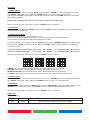
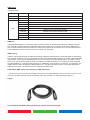
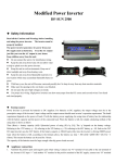
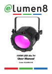
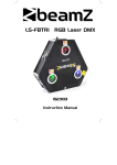
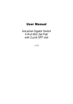
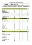
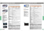
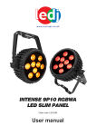
50W/100W LED Zoom
User Manual
Code: ELUM042 - 50W - (5600K)
Code: ELUM042A - 100W - (5600K)
Code: ELUM042C - 50W - (3200K)
Code: ELUM042D - 100W - (3200K)
1
2
Overview:
You should find inside the Elemen8 carton the following items:
1, LED Zoom
2, Instruction manual,
Technical Specifications:
3, Power Cable
DMX channels: 1 or 3 selectable
1 x 50W or 100W White LED (5600K or 3200K)
Dimming, master/slave and DMX modes
400Hz refresh rate
5-pin XLR in/out sockets
4 push button menu with LCD display
Powercon in/out sockets
Beam angle: 10-50 degrees
Power supply: 100-240V~50/60Hz
Power consumption: 50W version - 77W
Power consumption: 100W version - 126W
Dimensions: 350 x 165 x 255mm
Weight: 50W version - 4.6Kgs
Weight: 100W version - 5Kgs
Operating modes: 1, Dimming 0-100%
2, DMX
3, Master/slave
4, Channel select
5, Dimming curves
Overview:
FUSE
F2A~250V
POWER IN
POWER OUT
LCD DISPLAY
MENU
ENTER
UP
DMX IN
3
DOWN
DMX OUT
Operation:
1, Dimming Mode
To enter the dimming mode, press the “MODE” button to show “DIMMER” on the LCD display. Now press
the “ENTER” button and use the “UP” and “DOWN” buttons to set the brightness from 00-99.
Now press the “ENTER” button again to add strobe and use the “UP” and “DOWN” buttons to change the
flash speed from 00-99.
NOTE: C:99 = Dimming (00 = off, 99 = full on), F-99 = Flash (00 = off, 99 = fast)
When you are happy with your choice, press the “ENTER” button to confirm it.
2, Slave Mode
To enter slave mode, press the “MODE” button to show “SLAVE” on the LCD display. Now the unit will follow in
sequence with the master unit.
3, Dimming Curve Mode
The LED Zoom includes two sets of dimming curves.
The first is a Halogen emulation mode with a very smooth slow dimming and a small delay.
The second is an LED response with faster dimming and no delay.
To enter the dimming curve mode, press the “MODE” button to show “DIMMER CURVE” on the LCD display.
Now press the “ENTER” button and use the “UP” and “DOWN” buttons to select between the 4 dimming
curves from 01-08.
1-4 are for halogen response type : 01 = Linear,
5-8 are for LED response type : 05 = Linear,
02 = Square,
06 = Square,
03 = Inverse square,
07 = Inverse square,
04 = S-curve.
08 = S-curve.
When you are happy with your setting, press the “ENTER” button to confirm it.
LINEAR: the increase in light intensity appear to be linear as DMX value is increased.
SQUARE: light intensity control is finer at low levels and coarser at high levels
INVERSE SQUARE: light intensity control is coarser at low levels and finer at high levels
S-CURVE: light intensity control is fine at low levels and high levels and coarser at medium levels.
4, Channel Mode
To enter the channel mode, first press the mode button to show “CHANNEL” on the LCD display. Now press
the “ENTER” button and use the “UP” and “DOWN” buttons to select 1 or 3 channel mode.
5, DMX Mode
To enter the DMX mode, press the “MODE” button to show “DMX MODE” on the LCD display. Now press the
“ENTER” button and use the “UP” and “DOWN” buttons to select the DMX address from 001-512.
When you are happy with your setting, press the “ENTER” button to confirm it.
DMX Charts
1 channel mode:
Channel
Value
Function
CH1
0-255
Dimming 0-100% using the curve set on the fixture
4
DMX Charts
3 channel mode:
Channel
Value
Function
CH1
0-255
0-255
0-15
16-45
46-75
76-105
106-135
136-165
166-195
196-225
226-255
Dimming 0-100%
Strobe speed (slow to fast)
Dimmer curve and response select on fixture
Dimmer curve Linear response halogen
Dimmer curve Square response halogen
Dimmer curve Inverse Square response halogen
Dimmer curve S response halogen
Dimmer curve Linear response LED
Dimmer curve Square response LED
Dimmer curve Inverse Square response LED
Dimmer curve S response LED
CH2
CH3
DMX-512:
• DMX (Digital Multiplex) is a universal protocol used as a form of communication between intelligent fixtures
and controllers. A DMX controller sends DMX data instructions form the controller to the fixture. DMX data is
sent as serial data that travels from fixture to fixture via the DATA “IN” and DATA “OUT” XLR terminals located
on all DMX fixtures (most controllers only have a data “out” terminal).
DMX Linking:
• DMX is a language allowing all makes and models of different manufactures to be linked together and operate
from a single controller, as long as all fixtures and the controller are DMX compliant. To ensure proper DMX data
transmission, when using several DMX fixtures try to use the shortest cable path possible. The order in which
fixtures are connected in a DMX line does not influence the DMX addressing. For example; a fixture assigned
to a DMX address of 1 may be placed anywhere in a DMX line, at the beginning, at the end, or anywhere in the
middle. When a fixture is assigned a DMX address of 1, the DMX controller knows to send DATA assigned to
address 1 to that unit, no matter where it is located in the DMX chain.
DATA Cable (DMX cable) requirements (for DMX operation):
• The LED Zoom can be controlled via DMX-512 protocol. The DMX address is set on the back of the unit. Your
unit and your DMX controller require a standard 3-pin XLR connector for data input/output (figure 1).
Figure 1
Also remember that DMX cable must be daisy chained and cannot be split.
5
Notice:
• Be sure to follow figures 2 & 3 when making your own cables. Do not connect the cable’s shield conductor
to the ground lug or allow the shield conductor to come in contact with the XLR’s outer casing. Grounding the
shield could cause a short circuit and erratic behaviour.
Special Note: Line termination:
• When longer runs of cable are used, you may need to use a terminator on the last unit to
avoid erratic behaviour.
Termination reduces signal transmission problems
and interferance. it is always advisable to connect a
DMX terminal, (resistance 120 Ohm 1/4 W) between
pin 2 (DMX-) and pin 3 (DMX+) of the last fixture.
Using a cable terminator (part number CABL90) will decrease the possibilities of erratic behaviour.
5-Pin XLR DMX Connectors:
• Some manufactures use 5-pin XLR connectors for data transmission in place of 3-pin. 5-Pin
XLR fixtures may be implemented in a 3-pin XLR DMX line. When inserting standard 5-pin
XLR connectors in to a 3-pin line a cable adaptor must be used. The Chart below details the
correct cable conversion.
6
www.elumen8.co.uk