1
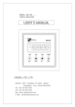
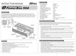
Receiver Connection Diagram
OPTIMA 7
CH6
2.4GHz 7 Channel Aircraft Receiver
CH1
CH2
CH3
LED
CH4
2.4GHz
Telemetric ADAPTIVE
LINK
AFHSS
FREQUENCY HOPPING
SPREAD SPECTRUM
CH5
SERVO
HITEC SPECTRA 2.4 Transmitter
& OPTIMA 7 Receiver
USER MANUAL
SERVO
BEC
ESC
Power Battery
SERVO
SPC
SERVO
SERVO
DATA
BAT/CH7
SERVO
1. Diagram for SPC system not used
Motor
OPTIMA 7
CH1
CH2
AFHSS
CH4
FREQUENCY HOPPING
SPREAD SPECTRUM
CH5
BEC
Power Battery
ESC
SERVO
CH3
2.4GHz
Telemetric ADAPTIVE
SERVO
CH6
2.4GHz 7 Channel Aircraft Receiver
LED
LINK
ADAPTIVE FREQUENCY HOPPING SPREAD SPECTRUM TECHNOLOGY
2.4GHz System
SERVO
SPC
SERVO
SERVO
DATA
BAT/CH7
SERVO
2. Diagram for SPC system in use
Motor
WARRANTY INFORMATION
HITEC RCD INC.
HITEC RCD KOREA INC.
653, YangCheong-Ri, Ochang-Eup, CheongWon-Gun,
Chung Buk Province, KOREA
PHONE:82-43-717-2074, FAX:82-43-717-2193
www.hitecrcd.co.kr
Adaptive Frequency Hopping
Spread Spectrum Technology
Telemetry System
Boosted Omni Directional
Antenna (BODA)
Supplementary
Power Connection (SPC)
SPECTRA 2.4
OPTIMA 6
AFHSS 2.4GHz Telemetric Transmitter
- All Hitec Module Type Transmitters and
Futaba 9C / 9Z Series Compatible
- Versatile Telemetric Data Port
(w/ Optional Sensors)
- Easy Link
- Size : 37.5 X 59 X 22.4mm
Stock# : 28315
Full Range AFHSS 2.4GHz 6ch Receiver
- Boosted Omni-Directional Antenna Applied
- Supplementary Power Connection (SPC)
- SmartScan Mode Selectable
- Size : 46.15 X 21.42 X 11.1mm
- Weight : 15g
Stock# : 28410
OPTIMA 9
OPTIMA 7
Full Range AFHSS 2.4GHz 9ch Receiver
- Dual Boosted Omni-Directional Antenna Diversity
- Supplementary Power Connection (SPC)
- SmartScan Mode Selectable
- Size : 47.95 X 28.5 X 15.35mm
- Weight : 22g
Stock# : 28425
Full Range AFHSS 2.4GHz 7ch Receiver
- Boosted Omni-Directional Antenna Applied
- Supplementary Power Connection (SPC)
- SmartScan Mode Selectable
- Size : 57 x 21 x 11.4mm
- Weight : 17g
Stock# : 28414
Product Specification
1. INTRODUCTION
Thank you for your purchase of Hitec’s 2.4GHz Aurora-9 System, and we are glad to introduce our
complete set of A.F.H.S.S Telemetry 2.4GHz through long research and develop process.
This manual contains complete instruction of Optima 2.4 and Spectra X series receivers.
Please read it carefully and thoroughly for your safe and comfortable fly in the field
2. WARNINGS
Following instructions are written for you and other’s safety sake,
please take your time and read it thoroughly.
Tip
Warning
Caution
Check
Tip
This product is developed exclusively for the hobby aero vehicles;
do not operate it in any other applicants
Flying Area : It is recommended flying only at approved area.
Please read and understand FCC rules and regulation to prevent from against any
Check law in your area. Also be careful not to threat other people at the time you are
flying an aircraft.
Avoid flying while it’s raining : The water could leak inside of transmitter or receiver to
get it malfunction. If it’s necessary then make sure your systems to be completely
water resistance.
Caution
To turn on or off the system : please keep the following sequence all the time.
Turn on the transmitter than the receiver and turn off the receiver and the transmitter.
Function Check : before the engine start or turn on the main power of the aircraft,
please turn on the system as explained above. Then make sure all the servos and
Check control surface is working properly. When any control surface is not moving properly,
never operate the aircraft until the problem solved.
Frequency Table
Model Check : make sure that your radio is powered up for the proper aircraft.
Especially if you have multiple aircraft with one radio it is commonly ignored until it
Check becomes a habit.
Range Check : To see the transmitter is working properly, do the range checks every time
before the flight. Make sure to hold the aircraft before you test the range.
Check When you reach the maximum range of the radio, the aircraft starts jitter and jitter dead.
Proper range should be approximately 30 meter from the plane. Detailed method can be
found later in this manual. (Power-Down Mode)
2
3
Available Frequency World Wide: 2.4056~2.4776GHz
4. Assembling a Folding Antenna
Assemble Folding Antenna with the antenna mount as picture bellow,
push Folding Antenna until you hear the “Click” sound.
How ton Setup and Use
For the Receiver :
- Press and hold the function button and turn on the power.
- Blue and red LEDs on the receiver blinks quickly for about 2 seconds then both LED will blink
twice very slowly and search for the module.
- When the red LED be steady on and the blue LED turns off indicates ID setting is completed.
After ID Setting (Link) :
- You need to turn the power off and on for the both transmitter and receiver.
They will notify you when it is linked with following indications depend on the mode you use.
A. Scan Mode: Two continuous beeping sounds with Red LED indicators on
B. Normal Mode: Four continuous beeping sounds with both LED indicators on.
- Each set is paired at default for your convenience.
Tip - In a Scan Mode, whenever one of them has been shut off or disconnected for
more than one second, both module and receiver need to be reboot
Tip
(turn the power off and back on).
- Due to its weak signal output, during the ID setting Process, it must be done
within 5m (15ft).
- LED Indicator Field Guide Card (LED I.C.) allows you to have quick notification of
a module and a receiver’s status. We recommend you to carry the LED I.C. for
your convenience.
2. Fail-Safe and Hold Mode Setup
1. ID Setting
ID Setting is a feature to match a set of Transmitter and receiver ID to bind each other.
Once their ID is set, no other transmitter nor receiver can interfere during its operation,
consequently such feature gives user a maximum security. Also you can be free from carrying
multiple set of x-tals to avoid interference with other flyers. Further more, depends on your
needs, multiple receivers can have same ID to be used with one module for multiple planes.
Each set is paired at default for your convenience.
What does Fail-Safe do?
When interference occurs, the Optima X series receiver set the servos take up a pre-determined
position, previously stored in the receiver. If FAIL-SAFE has not been activated, the signal is
switched off after the HOLD period (1 sec.). This means that the servos become “soft” and
remain in their last commanded position under no load (this may equate to full-throttle!)
until a valid signal is picked up again.
In the interests of safety, we recommend that FAIL-SAFE should always be
activated, and the FAIL-SAFE settings should be selected so as to bring the model
Note to a non-critical situation (e.g. motor idle / electric motor OFF, control surfaces
neutral, airbrakes extended, aero-tow release open, etc.)
For the Transmitter :
- Press and hold the Function button and turn on the power.
- The Blue LED will blinks for about 4~5 seconds and turns off, then Red LED blinks and
search for the receiver.
Setup Method:
1. Switch on the transmitter, then the receiver. Both LEDs glow constantly:
2. Press and hold the receiver function button for 2~4 second then LEDs will slowly blinks to
notify the receiver is in F-S mode.
3. From the moment you release the button, receiver will count 5 sec. During the time both
LEDs blinks rapidly, move all the transmitter sticks and other controls to the desired
FAIL-SAFE positions (e.g. motor idle, control surfaces neutral).
4. After 5 sec Optima X will save the F-S Position and reboot automatically.
- FAIL-SAFE is now activated, and the FAIL-SAFE positions are stored.
8
9
How to turn F-S OFF?
1. Do the same as “How to Setup” step 1 and 2.
2. Instead of setup F-S Position, push the function button once more.
- F-S Mode is now deactivated and Hold mode is activated instead.
In a case FAIL-SAFE is deactivated, the FAIL-SAFE Position settings are also deleted!
Note
Testing the Fail-Safe Settings
Move the sticks to positions other than the FAIL-SAFE settings, and then switch off the
transmitter. The servos should now move to the FAIL-SAFE positions previously stored,
after the HOLD period (1 sec.) has elapsed.
Note
The FAIL-SAFE settings must be checked every time before you run the
engine/motor and brought up to date.
3. Range Check (Power down) Mode Setup
Unlike the conventional PPM or PCM radios 2.4GHz system uses rubber duck antenna which
you cannot adjust the length. Instead, use Power-Down Mode to reduce the signal strength in
certain rate to shorten the length. Once Power-Down Mode is activated it runs for about
90 second, and the range become shorten in length to approximately 30 meter.
How to use Power Down?
1. Press the button on the module for 1~4 sec, then both LED will turn on with short two
continuous “Beep!” sound, then release the button. The 90-second countdown starts from the
time button released. The proper power down range should be approximately in
30 meter range.
Check
When case the range check finished within 90 second or entered in this
mode by mistake, press the button again to escape.
Check
Be noticed that using Normal Mode can be effected by various factors,
such as an area where you at, or a flight condition
(crowded 2.4GHz equipped system running area).
How to setup:
1. Press and hold the button for more than 5 seconds, until both LEDs will turn on with
one long “Beed~” sound which indicates it is in Scan/Normal Selection Mode. Then release
the button to see the LEDs which indicates your current mode, Scan or Normal mode.
Tip
Tip
The factory default setup is Normal Mode.
2. Only the red LED turns on with short continuous “Beep! Beep!” sound is notifying you,
it’s in Scan Mode.
3. Both LEDs turns of with short continuous “Beep! Beep! Beep! Beep!” sound is
notifying you, it’s in Normal Mode.
4. Press the button to switch between the modes.
5. Telemetry System
Hitec’s sensational 2.4GHz telemetry system brought you a whole new concept of being an
R/C flyer. Unlike conventional system, your plane will give you a feed back during the flight,
such as low in fuel warning, range-out warning, battery current residual and much more
information can be given in the future, which will help you to concentrate more on your
flight not on other things.
I. LOW BATTERY WARNING:
Spectra 2.4 will recognize a receiver battery type automatically among 4 cell and
5 cell NiMH and 2 cell LiPo Battery.
Red LED will blink fast. You will hear three continuous beeping sounds for low battery warning.
II. RANGE-OUT WARNING:
Depends on the area you fly, as well as your model’s flight condition the maximum range also
could be varied. Approximately 200 meter before your plane loses connection the range-out
warning will be activated and start warns you with the alarm sound.
Also both LEDs will blink rapidly.
4. Scan Mode Setup
Hitec’s 2.4GHz Spectra Transmitter and Optima X series receivers has two different modes to
scan the frequency. One is Normal Mode, factory default, and another is Scan Mode.
Each modes differentiated as follow:
- Scan Mode in Use : Every time system powered up, it scans frequency (channels) in the
area to choose the cleanest band to use. This can optimizes the frequency traffics depends
on the flight condition with other 2.4GHz radios.
- Normal Mode in Use : A Transmitter and a receiver will keep using the same frequency
(channel) band at the first time of ID setting.
10
6. SPC (Supplementary Power Connection) System
SPC (Supplementary Power Connection) System is exclusive receiver power supplement
system directly powering the receiver from the main power source of an Electronic Powered
Aerial Vehicles. Therefore, it could use up to 35 Volts for the receiver; however, you still need to
supply power for your own servos with the four or five cell NiMH receiver battery.
SPC system is made for later use of telemetry system such as GPS.
11