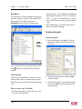
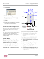
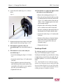
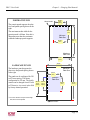
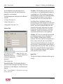
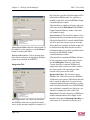
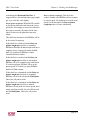
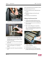
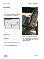
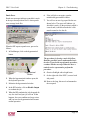
1
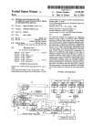
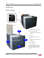
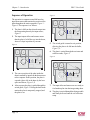
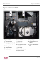
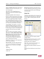
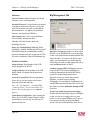
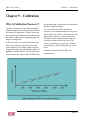
DPX 2
User Guide
AO45215
Rev. 4
Preface
DPX 2 User Guide
Preface
Copyright
ECRM contact information
© Copyright 2007 ECRM Imaging Systems
All rights reserved.
ECRM Imaging Systems
554 Clark Road
Tewksbury, MA 01876
USA
Tel: +001 978-851-0207
Fax: +001 978-851-7016
DPX 2 User Guide, v. 1.0
May 2007
Doc. No. AG45215, Rev. 4
This manual, as well as the software described in
it, is provided under licence and may only be used
or copied in accordance with the terms of that
licence. The information in this manual is subject
to change, without notice, and should not be
construed as a commitment by ECRM Imaging
Systems. ECRM Imaging Systems assumes no
responsibility or liability for any errors or inaccuracies that appear in this manual.
All rights reserved. No part of this manual may be
reproduced or transmitted in any form, or by any
means, without the prior written permission of
ECRM Imaging Systems.
Windows is a registered trademark of Microsoft
Corporation.
All other brand or product names are trademarks
or registered trademarks of their respective
companies or organizations.
ii
Web: www.ecrm.com
Table of Contents
DPX 2 User Guide
Table of Contents
Preface
Chapter 1 – Using this Guide
Introduction .................................................................................................................................... 1.1
Warnings and Notes ................................................................................................................ 1.1
Warnings .......................................................................................................................... 1.1
Notes ................................................................................................................................. 1.1
Using Acrobat Reader to view this Guide .............................................................................. 1.1
Bookmarks ....................................................................................................................... 1.2
Using hot links ................................................................................................................. 1.2
Printing this guide ................................................................................................................... 1.2
Chapter 2 – Introduction
Description ..................................................................................................................................... 2.1
Computer-to-Plate System (CtP) ............................................................................................ 2.1
The DPX 2 Unit ...................................................................................................................... 2.2
Exterior of Machine ................................................................................................................ 2.2
Interior of Machine ................................................................................................................. 2.3
Sequence of Operation ............................................................................................................ 2.4
Exposure and Processor Module ............................................................................................. 2.5
Chapter 3 – Safety
Introduction .................................................................................................................................... 3.1
General ........................................................................................................................................... 3.1
Laser ............................................................................................................................................... 3.1
Safety labels on DPX 2 .................................................................................................................. 3.2
Regulatory Information .................................................................................................................. 3.3
Electromagnetic Emissions ..................................................................................................... 3.3
Identification and Certification Label (ratings plate) .............................................................. 3.4
Page 1
Table of Contents
DPX 2 User Guide
Chapter 4 – Basic Operation
Introduction ....................................................................................................................................4.1
Starting the DPX 2 ..........................................................................................................................4.1
Shutting Down the DPX 2 ..............................................................................................................4.2
RIP PC Display ...............................................................................................................................4.2
DotManager ...................................................................................................................................4.3
RIPMate .........................................................................................................................................4.3
Output Controller ............................................................................................................................4.4
Active Queue ...........................................................................................................................4.4
Held Queue ..............................................................................................................................4.4
Job Names ................................................................................................................................4.4
Start/stop processing ................................................................................................................4.4
Start Output .......................................................................................................................4.4
Stop Output .......................................................................................................................4.5
Repeating a Job ........................................................................................................................4.5
Removing/Deleting a Job ........................................................................................................4.5
Previewing a Job ......................................................................................................................4.6
Connecting to the Front-End ..........................................................................................................4.6
Chapter 5 – Changing Plate Material
Introduction ....................................................................................................................................5.1
Unloading material .........................................................................................................................5.1
Changing the media roll .................................................................................................................5.1
Loading material .............................................................................................................................5.2
Punch-related Media Adjustments .................................................................................................5.3
Portrait Punch. .........................................................................................................................5.3
Landscape Punch .....................................................................................................................5.4
Chapter 6 – Working with DotManager
General ...........................................................................................................................................6.1
Menus ......................................................................................................................................6.1
File menu ..........................................................................................................................6.2
View menu ........................................................................................................................6.2
Tools menu .......................................................................................................................6.2
Help menu .........................................................................................................................6.2
Buttons .....................................................................................................................................6.2
Tabs .........................................................................................................................................6.3
Page 2
DPX 2 User Guide
Table of Contents
Platesetter Tab ......................................................................................................................... 6.3
Media Tab ............................................................................................................................... 6.4
Service Tab ............................................................................................................................. 6.5
General ............................................................................................................................. 6.5
Pump issues ...................................................................................................................... 6.5
Add Volume ..................................................................................................................... 6.5
I/O Test button ................................................................................................................. 6.5
Calibration of Replenishment Pumps ............................................................................... 6.5
Preferences Tab ....................................................................................................................... 6.6
Online Processor .............................................................................................................. 6.7
Anti Oxidant ..................................................................................................................... 6.7
Standby (Energy Save mode) Processor .......................................................................... 6.7
Standby (Energy Save mode) Anti Oxidant ..................................................................... 6.7
Setup Tab ................................................................................................................................ 6.7
Firmware .......................................................................................................................... 6.8
Product LicenseKeys ........................................................................................................ 6.8
RipManagement Tab ............................................................................................................... 6.8
License Tab ...................................................................................................................... 6.9
Spool Tab ......................................................................................................................... 6.9
Imagesetter Tab .............................................................................................................. 6.10
Chapter 7 – Maintenance
Introduction .................................................................................................................................... 7.1
Emptying Punch Waste .................................................................................................................. 7.1
Processor Unit ................................................................................................................................ 7.1
Draining the Processor Unit .................................................................................................... 7.1
Cleaning the Processor Unit .................................................................................................... 7.3
Filling of the Processor Unit ................................................................................................... 7.4
Cleaning the Waste Drain and Hose ....................................................................................... 7.5
Additional Cleaning and Lubrication Recommendations ....................................................... 7.5
Items Requiring Cleaning Once per Year ........................................................................ 7.5
Items Requiring Lubrication Once per Year .................................................................... 7.5
Chapter 8 – Troubleshooting
Error messages ............................................................................................................................... 8.1
Page 3
Table of Contents
DPX 2 User Guide
Chapter 9 – Calibration
Why Is Calibration Necessary? ......................................................................................................9.1
Chapter 10 – Technical Specifications
Index
Page 4
DPX 2 User Guide
Chapter 1 – Using this Guide
Chapter 1 – Using this Guide
Introduction
This section includes the following topics:
• Warnings and Notes, page 1.1.
• Using Acrobat Reader to view this Guide,
page 1.1.
• Printing this guide, page 1.2.
Using Acrobat Reader to view this
Guide
Note The instructions that follow are for Acrobat
Reader v7.0.
If you are viewing this guide using Acrobat Reader
you can move around the guide using Acrobat’s
navigation buttons, for example:
Warnings and Notes
Go to the first page of the guide
Warnings
Go back one page
The warnings in this manual are intended to
protect you from injury or protect the DPX 2 or
your plates from damage. Read all warnings
carefully and follow any instructions they include.
Warnings appear in bold print, like this:
WARNING: When working with DPX 2 you
must protect yourself from injury and protect
DPX 2 from damage.
Notes
The notes in this manual give additional information on using DPX 2.
Go forward one page
Go to the last page of the guide
Go back to previous view
Go forward to next view
Fit page in window
Close bookmarks
Notes appear in Italics, like this:
Note The instructions in this manual are for the
DPX 2 system.
Page 1.1
DPX 2 User Guide
Chapter 1 – Using this Guide
Bookmarks
You can use the Acrobat bookmarks to navigate to
a specific chapter or section of this manual. If the
bookmarks are not visible, click on the
Bookmarks tab (see below) to display them:
• Cross references: you will find these throughout
the manual, for example, “Refer to “Starting the
DPX 2” on page 4.1 for instructions”. Click on
the section reference to take you to the relevant
page.
• On the Index page: click on the index entry to
take you to the relevant page.
Printing this guide
To print this guide:
1. In Acrobat Reader select Print… from the
File menu to display a dialog similar to the
following:
Click on a link to move to a specific chapter. Click
on a
link to view the sub-sections within a
chapter.
Using hot links
You can use Acrobat Reader’s ‘hot links’ to move
quickly to the section you want (when you place
the mouse cursor over a hot link it turns into a hand
icon).
There are three types of hot link:
• On the Contents page: click on the entry to take
you to the relevant section.
Page 1.2
2. Select the required printer from the Name
pull-down menu.
3. Set the other options, such as the page range,
then click on OK to print this guide (or the
specified pages).
DPX 2 User Guide
Chapter 2 – Introduction
Chapter 2 – Introduction
Description
This chapter describes the DPX 2 system:
• Computer-to-Plate System (CtP), page 2.1.
• The DPX 2 Unit, page 2.2.
• Exterior of Machine, page 2.2.
• Interior of Machine, page 2.3.
• Sequence of Operation, page 2.4.
• Exposure and Processor Module, page 2.5.
Computer-to-Plate System (CtP)
The platesetter can manage a variety of color
demands, satisfying a wide range of imaging
needs. The DPX 2 targets all black and white
applications as well as high-end spot-color, and
quality 4-color jobs.
Time Saving The DPX 2 bypasses the conventional film processing stage entirely by integrating
functions such as edge-to-edge exposure, plate
punching, processing, cutting to size, drying and
stacking, in one compact unit.
Perfect Accuracy Based on an internal drum
imaging device with a red laser diode (658 nm),
the DPX 2 offers unmatched image accuracy and
repeatability, ensuring that each separation is in
register.
Intelligent Optimization The DPX 2 contains
two cassettes, holding up to 61 metres of material
each.
High Quality Register An internal register
punch system is optional.
Cost-Effective Production The DPX 2 is a
highly productive and economic solution. The
technology has proven to reduce the processing
time by 50%, without compromising the ultimate
quality.
The DPX 2 digital platesetter produces pressready polyester plates for a variety of printing
jobs. The entire process only takes a few minutes
and is carried out in full daylight.
Workflow All interaction with the DPX 2 is done
via the RIP PC, which includes the DotManager
program, the platesetter’s user interface.
Page 2.1
DPX 2 User Guide
Chapter 2 – Introduction
The DPX 2 Unit
Exterior of Machine
Figure 1
B
A
A
Figure 2
B
A On/Off Switch on lower left side
Left
B Lid for plate magazines
D
G
To open lid lift upwards to upright
position
F
C Exit tray
C
D Processor module door - lift to
remove
Rear
Lift door to remove
Front
to remove
F
D
E
Right
Page 2.2
E Plate exposure module door - lift
Plate magazine 1
G Plate magazine 2
Note: In this manual, the terms
Front, Rear, Right, and Left always
refer to the orientations shown in
Figure 2.
DPX 2 User Guide
Chapter 2 – Introduction
Interior of Machine
Figure 3
D
D
A
B
F
G
HJ K
L N Y
M
X T O
A. Plate magazine 1 (roll A)
M. Activator tank
B. Plate magazine 2 (roll B)
N. Activator temperature sensor
D. Empty roll sensors
O. Stabilizer tank
F. Imagesetting drum
P. Dryer module
G. Imagesetter, laser optics and
Q. Dryer temperature sensor
mirror (Flying spot system)
H. Cutter (Knife)
J. Drum sensor
K. Switch guide
L. Buffer
S
R
R. Plate exit collection ramp
Z
U
V
P
W Q
V. Switch for draining waste
container
W. Valve for connecting drain
hose
X. Heating element
Y. Drain pipe (blue)
Z. Drain pipe (black)
S. Exit sensor
T. Waste container (chemistry)
U. Level sensors, activator and
stabilizer
Page 2.3
DPX 2 User Guide
Chapter 2 – Introduction
Sequence of Operation
Figure 5
The operation is computer controlled based on
input from sensors that monitor the position of the
plate throughout the entire operation, Figure 3 Figure 6. The sequence is as follows:
1. The plate is fed from the selected cassette into
the imagesetting drum by the input rollers,
Figure 4.
2. The input/output rollers and sensors ensure
that the plate is fed all the way into the drum,
where it is kept in position by vacuum.
Figure 4
5. The switch guide is turned to exit position,
allowing the plate to be fed into the buffer,
Figure 3, L.
6. The plate is carried through the activator and
stabilizer tanks, Figure 6.
Figure 6
3. The correct position of the plate inside the
drum is ensured by input from the drum sensor
to the computer. In this position, the plate is
exposed right to left in the drum by the laser
optics and mirror, Figure 3, G.
4. After exposure the plate is guided through the
switch guide, Figure 5. During the backwards
motion the plate is temporarily stopped, and
the plate is cut.
Page 2.4
7. The input rollers and sensors are now ready to
feed another plate into the imagesetting drum.
8. The plate is carried through the drying module
and finally delivered onto the exit collection
ramp.
DPX 2 User Guide
Chapter 2 – Introduction
Exposure and Processor Module
Figure 7
J
C
I
H
F
M
G
B
D
L
A
N
D
E
K
Exposure module
Processor module
L Replenish pipes
A Imagesetting drum
F
M Switch for draining waste
B Imagesetter, laser optics and
G Stabilizer tank
mirror (Flying spot system)
Activator tank
H Level sensors for activator
C Plate magazines
and stabilizer
D Punch waste tubes
I
Dryer module
E Punch waste box
J
Plate exit collection ramp
container
N Valve for connecting drain
hose
K Replenish container
Page 2.5
Chapter 2 – Introduction
Page 2.6
DPX 2 User Guide
DPX 2 User Guide
Chapter 3 – Safety
Chapter 3 – Safety
Introduction
This chapter describes the safety precautions you
must observe when operating DPX 2.
• General, page 3.1
• Laser, page 3.1
• Safety labels on DPX 2, page 3.2.
• Regulatory Information, page 3.3
General
Procedures that go beyond the normal operation
and user maintenance described in this guide must
be carried out by a technician who has been trained
to work on the DPX 2.
Although every precaution has been made to
produce a safe product, we strongly recommend
that the below points be observed.
• The equipment must be properly grounded when
connected to electrical outlets.
• Turn off power:
• before connecting or disconnecting cables,
and,
• before carrying out service or adjustment
operations.
• Wear protective gloves when handling chemistry
and avoid spilling the fluids.
• Always check that the actual media width in
Media Management corresponds to the actual
media being used.
• The spinner in the platesetter cannot be started in
an ambient temperature of less than 15 degrees
Celsius (59 degrees Fahrenheit).
Laser
The system is classified as a Class one (I) laser
product that contains a Class 3B (IIIb) laser
system. This classification means that an operator
is exposed to no hazardous laser light during
operation and maintenance. The laser itself,
however, is a Class 3B (IIIb) laser device, and
emits visible laser light which is considered
hazardous by FDA published limits.
IMPORTANT WARNING: Modifications to the
machine or performance of procedures other
than those specified in this guide may result in
hazardous laser light exposure.
WARNING: Only authorized service
personnel may override the interlock system.
The warning labels on the DPX 2 are intended
for such personnel.
• Do not remove covers or shielding.
• Do not install/use the equipment close to inflammable gases and vapors.
• Do not in any way make unauthorized modifications of the equipment.
Page 3.1
DPX 2 User Guide
Chapter 3 – Safety
Safety labels on DPX 2
This section describes the safety labels.
Caustic chemicals warning on processor cover:
Label
Location
Laser hazard warning label located
in the optics area behind removable
covers (left). See also the section
“Laser” on page 3.1 for details on
laser safety.
High-voltage warning label identifying parts that have dangerous voltage inside. Located on transformer
and heater relay covers. Do not
attempt to open these covers.
General avoidance warning label
located in the optics area behind
removable covers to the plate exposure module.
Caustic Chemicals. Avoid contact with
eyes and skin when filling and draining.
WARNUNG
Ätzende Chemikalien. Vermeide beim
Füllen und Ablassen Berührung mit Haut
und Augen.
ATTENTION
Hand/roller entanglement hazard
label located on the plate magazine
covers and on outside cover (top lid
– at output rollers).
Produits chimiques et caustiques. Pendant
remplissage et soutirage eviter le contact
avec la peau et les yeux.
Hot surface warning label located in
the side of processor and dryer cover
– behind right removable door.
ATENCION
Momentary switch label located
over the waste pump switch in the
processor module.
Fuse labels located near each fuse
holder. They indicate the correct rating of the fuse.
Earth (ground) label on chassis connections in the platesetter.
Page 3.2
CAUTION
Productos químicos y cáusticos. Al
llenado y drenaje evitar contacto con la
piel y los ejos.
ATTENZIONE
Prodotti chimini caustico. Al rabboccatura
e spillare evitare contatto con la pelle et gli
occhi!
DPX 2 User Guide
Wait 20 seconds warning on spinner:
Chapter 3 – Safety
The standards for electromagnetic emissions are
Part 15, Subpart J of the FCC rules. The system
was tested to Class A limits. The following statements are required by the FCC:
Changes or modifications to this unit not expressly
approved by the party responsible for compliance
could void your authority to operate the
equipment.
WARNING: Wait 20 seconds for the spinner
motor to settle after the power has been turned
off.
Regulatory Information
Electromagnetic Emissions
DOC- Canada
The Canadian Department of Communications
requires compliance with the Radio Interference
Regulations, ICES -003.
This digital apparatus does not exceed the Class A
limits for radio noise emissions from digital
apparatus set out in the Radio Interference Regulations of the Canadian Department of Communications.
This equipment has been tested and found to
comply with the limits for a Class A digital device,
pursuant to Part 15 of the FCC Rules. These limits
are designed to provide reasonable protection
against harmful interference when the equipment
is operated in a commercial environment. This
equipment generates, uses, and can radiate radio
frequency energy and, if not installed and used in
accordance with the instruction guide, may cause
harmful interference to radio communications.
Operation of this equipment in a residential area is
likely to cause harmful interference in which case
the user will be required to correct the interference
at his or her own expense.
Compliance with applicable regulations depends
on the use of shielded cables, which the user may
be responsible for procuring.
EMC Directive - Europe
Complies with EN 55011: 1998
This is a Class A product. In a domestic
environment this product may cause radio interference in which case the user may be required to
take adequate measures.
FCC - USA
Page 3.3
Chapter 3 – Safety
Identification and Certification
Label (ratings plate)
The identification and certification label shown
below is attached to the cover of the platesetter
unit, near the power entry receptacle.
Page 3.4
DPX 2 User Guide
DPX 2 User Guide
Chapter 4 – Basic Operation
Chapter 4 – Basic Operation
Introduction
This chapter covers these subjects:
• Starting the DPX 2, page 4.1.
• Shutting Down the DPX 2, page 4.2.
• RIP PC Display, page 4.2.
• DotManager, page 4.3.
• RIPMate, page 4.3.
• Output Controller, page 4.4.
• Connecting to the Front-End, page 4.6.
Note This user guide shows windows and
dialogs from RIP PCs running Windows XP
or Windows 2000.
4. Press CTRL + ALT and keep them pressed
while pressing the DELETE key.
The Log-In screen will appear ensuring the
correct setup. The default setup is normally
the correct one. If this default setup is
incorrect, please contact your local support
engineer.
5. Launch the DotManager program.
• The screen shown below opens.
Starting the DPX 2
1. Switch on the DPX 2.
The DPX 2 performs self tests, clears the
media path, and checks if the punches are in
home position. This initilization takes about 3
minutes.
2. Switch on the RIP PC.
3. Wait for this window to appear. (It may take to
3 minutes, depending on your computer type).
The traffic lights at the bottom of the window
are off while the DPX 2 is initilaizing. After it
initializes, the green light comes on. The green
light indicates the DPX 2 is “online” and ready
to use.
.
Page 4.1
DPX 2 User Guide
Chapter 4 – Basic Operation
If the DPX 2 detects a fault condition during
initialization, it displays an error message in
the Message Log. For example, if it detects a
punch die is not in home position (not closed),
it displays this message:
9. Switch off the computer, if it does not do so
automatically.
RIP PC Display
The DPX 2 does not have a control panel or
display. All DPX 2 settings and operations are
made from the RIP PC. During normal operation
the following programs are needed.
To correct this or other fault conditions that
may occasionally be reported, refer to Chapter
8 –“Troubleshooting”. For instance, to correct
the fault condition shown above, see “Punch
Error” on page 8.5.
DotManager
RIPMate incl. Output Controller
Shutting Down the DPX 2
Click on the Start button .
The icons shown above are for the available
programs. The RIPMate program can display one
or more windows on the screen.
Note The RIPMate RIP may be replaced by the
corresponding ECRM RIP.
6. Select Shut down from the drop-down list.
7. Click the OK button.
8. Switch off the DPX 2 unit.
Page 4.2
DPX 2 User Guide
DotManager
Chapter 4 – Basic Operation
RIPMate
The RIPMate RIP handles communication from
the front-end application users, interprets PDF and
PostScript data, and controls the exposure of plates
in the DPX 2.
The DotManager program is the user interface to
the DPX 2. It monitors the platesetter and the builtin processor, and displays real time status information about both.
DotManager is used to load and unload plate
materials.For details, see “Changing Plate
Material” on page 5.1.
For more about DotManager, refer to Chapter 6 –
“Working with DotManager” for additional information.
The RIPMate window displays RIP activities and
errors in a log section below the toolbar, also
referred to as the RIPMate Monitor.
For more details, see “Output Controller” on
page 4.4 and “Connecting to the Front-End” on
page 4.6.
Please refer to the RIPMate user documentation
for additional information.
Note The RIPMate RIP may be replaced by the
corresponding ECRM RIP.
Page 4.3
DPX 2 User Guide
Chapter 4 – Basic Operation
Output Controller
Held Queue
Using the Output Controller the operator controls
which and when a specific plate is to be exposed or
re-exposed.
This queue shows processed jobs and jobs that
have generated an error. A black dot next to the job
name indicates an error has occurred. Check the
RIP Monitor for error message.
Job Names
The name of the job received by the front-end.
After the name the color is displayed:
[K] Black
[M] Magenta
[Y] Yellow
The Output Controller window is part of the
RIPMate program.
1. If the above window does not appear, select
Output Controller... from the Output menu.
[C] Cyan
[?] The name of the spot color.
Start/stop processing
To make the Output Controller window active,
click on it or open it as described in the section
“Output Controller” on page 4.4.
Start Output
1. Point at Disable Output and press the left
mouse button to clear the checkbox.
2. The Output Controller window opens.
Active Queue
This queue shows all jobs ready for processing.
The jobs will be processed in top-down order.
Page 4.4
DPX 2 User Guide
2. RIPMate’s Output Controller now displays
jobs being processed.
Chapter 4 – Basic Operation
Repeating a Job
Stop Output
1. To make the Output Controller window active,
click on it or open it as described in the section
“Output Controller” on page 4.4.
1. Point at Disable Output and press the left
mouse button to check the checkbox.
2. In the Held Queue point the mouse at the job
to be repeated.
3. Press the left mouse button and hold it down
while pulling the job from the Held Queue to
the Active Queue. Release the mouse button.
Note When the output is stopped it is still possible
to receive and interpret jobs from the front-end. The
plates received from the front-end will merely be
placed in the Active Queue.
The job has now been moved from the Held Queue
to the Active Queue and will be exposed according
to its position in the queue.
Note By placing the job at the top of the Active
Queue, it will be exposed before the other plates.
Removing/Deleting a Job
1. To make the Output Controller window active,
click on it or open it as described in the section
“Output Controller” on page 4.4.
2. Point at the job in the Held Queue which
should be removed and press the left mouse
button down.
Page 4.5
Chapter 4 – Basic Operation
DPX 2 User Guide
3. Click on the Remove button and the job will
disappear.
1. If the menu entry called Input Queue is present
in RIPMate, the connection to the front-end is
already established.
4. Click the Yes button, if the job should be
deleted.
2. Otherwise, select Start Inputs from the
RIPMate menu in RIPMate.
Note By holding the Shift key down, a range of
plates can be selected, and by holding down the Ctrl
key, several individual plates can be selected.
Previewing a Job
1. To make the Output Controller window active,
click on it or open it as described in the section
“Output Controller” on page 4.4.
2. Point at the job in the Held Queue which
should be previewed and press the left mouse
button down.
3. Click on the Roam button.
The job is displayed on the screen in 1:1 (one pixel
on the screen represents one pixel on the plate).
Note By clicking on the Reduce Roam button, a
zoom effect is achieved.
Connecting to the Front-End
In order to enable the front-end to send jobs to the
RIP, the Input Queue must be started.
Page 4.6
The connection to the front-end will now be established.
DPX 2 User Guide
Chapter 5 – Changing Plate Material
Chapter 5 – Changing Plate Material
Introduction
Changing the media roll
This chapter explains:
Here’s how to replace an empty roll of media with
a full new roll of media of the same size.
• Unloading material, page 5.1.
• Changing the media roll, page 5.1.
• Loading material, page 5.2.
• Punch-related Media Adjustments, page 5.3
1. Open the magazine lid (Figure 1, B) to gain
access to the plate magazines.
2. Open the plate magazine cover (Figure 2, F or
G).
3. Remove the media spindle from the magazine.
Unloading material
Figure 8
The following assumes the system is up and
running and has been outputting jobs.
1. Stop processing by activating the Disable
output button. See section “Start/stop
processing” on page 4.4.
2. Activate the DotManager window.
F
3. Select the Platesetter tab in the DotManager
window.
4. Remove the old core (“Figure 8”, F) by
taking off the threaded hub (Figure 8, A) and
removing the end cap (Figure 8, C).
5. Place the empty core on the floor, and place
the empty spool on top of it.
6. Take a new roll of material and mount it on the
spool.
7. Replace the end caps.
The information reflects the currently loaded
cassette.
4. Press the Unload button.
Page 5.1
Chapter 5 – Changing Plate Material
DPX 2 User Guide
magazine. Ensure that the gear wheel (Figure
8, E) on the right side is fitted correctly into
the drive gear.
2. Remove the white tape from the roll and
position the leading edge of the roll at the nip
of the inlet rollers at the bottom of the
magazine. Guide the leading edge of the roll
into the nip of the feed rollers.
3. Press the Dot Manager Preload button.
Note Not firmly tightening the end caps may affect
the edge accuracy of the image.
Loading material
1. Place the roll shaft with a new roll mounted in
the bearings inside the magazine so that the
thumb screw faces the left side of the
Note The emulsion side is matt and dark and
faces inwards on the roll. It is important that
the front edge of the plate material is not
folded or creased and that all tape has been
carefully removed.
Note If length (M) is zero, the length of the
material should be specified, otherwise the
loading process will generate an error.
Wait for the material to load.
When a new roll has been fitted, the first 1-2
plates cannot be used because of daylight
exposure during loading.
4. Select the Media to Form Feed.
Page 5.2
DPX 2 User Guide
Chapter 5 – Changing Plate Material
5. Click Form Feed.
Center of
notch
6. Click Yes to form feed a plate.
220mm
8.66 in
110mm 110mm
4.33 in 4.33 in
Center of
notch
Center of Media
Media
Repeat the last two steps until all daylight
exposed material is fed.
Center of Shaft
7. Click OK.
8. To expose, start processing again. See section
“Start/stop processing” on page 4.4.
Punch-related Media Adjustments
There are two plate punches in the DPX 2. One is
a portrait punch, and the other is a landscape
punch.
Note The portrait punch supports media widths up
to 420mm. Media wider than 420mm must be
punched on the landscape punch, which supports
widths up to 460mm.
Portrait Punch.
The portrait punch has 2 punch blocks. They are
220 millimeters apart, on center. The notches
produced by the blocks are 10.5mm deep.
In most cases, you will want the punches to be
centered in the media. For this to happen, it is
essential that the roll of media be centered on
media spindle shaft, as shown in the next figure.
Spindle
Shaft
Scribe Mark
at center of
the shaft
Core
420mm
maximum media width
Here’s how to center a roll of media on the shaft.
1. Open magazine # 1 and remove the roll of
media and/or the media spindle from
magazine.
Note Magazine 1 works with Media Spindle #1,
which is customarily used for portrait imaging.
2. Remove the knurled hub and the left end cap
from the shaft.
3. Remove the media/empty core, if present.
4. Measure the width of media you are about to
install. Or, refer to the label on the media
shipping carton, if you have it.)
5. Calculate and record half the media width. For
example, for 340 mm-wide media, the value
would be 170 mm.
Page 5.3
DPX 2 User Guide
Chapter 5 – Changing Plate Material
6. Locate the scribe mark (Figure 9, A) shown
below.
Figure 9.
B
10. If the distance is significantly different than
the value you recorded in step 5:
• Remove the retaining pin (Figure 9, C).
• Move the end cap along the shaft to a point
at which distance between the scribe mark
(Figure 9, A) and the inside of the end cap
(Figure 9, B) is roughly equal to the value
you recorded in step 5.
A
• Align the hole in the end cap’s threaded
sleeve with the nearest hole in the shaft.
• Insert the retaining pin through the holes in
the threaded sleeve and the spindle shaft.
C
D
7. Measure the distance between the scribe mark
and the inside of the end cap (Figure 9, B).
• Loosen the inside (Figure 9, D) and outside
lock nuts.
• Position of the end cap so that the distance
between the inside of cap and the scribe
mark is exactly equal to the value you
recorded in step 5.
• Tighten the lock nuts.
8. If the distance equals the value you
recorded in step 5, leave the end cap where it
is!
Landscape Punch
9. If the distance is close to the value you
recorded in step 5:
The landscape punch has two punch elements.
They are 425 millimeters apart, on center.
• Leave the retaining pin (Figure 9, C) where
it is.
• Loosen the inside (Figure 9, D) and outside
lock nuts.
• Finely adjust the position of the end cap
until the distance between the inside of the
cap and the scribe mark is exactly equal to
the value you recorded in step 5.
• Tighten the lock nuts.
Page 5.4
Landscape notch depth is governed by the setting
of right end cap. At the factory, the right end cap
on Media Spindle # 2 is set for a 10.5mm notch
depth
Note Media Spindle #2 is the landscape imaging
spindle. If you change the factory setting of the right
end cap on Media Spindle #2, the edge of the media
will get closer to (or father from) the punch elements,
resulting in deeper (or shallower) notches.
DPX 2 User Guide
Chapter 5 – Changing Plate Material
PORTRAIT PUNCH
19mm border*
The portrait punch supports the plate
sizes and punch spacing shown at the
right.
220 mm
Punch
Spacing
250 mm
(10 in)
The maximum media width for the
portrait punch is 420mm. Note this is
40mm narrower than the maximum
width the landscape punch supports.
Minimum
Plate Size
550 mm
(21.6 in)
250 mm
(10 in)
.
Maximum
Plate Size
420 mm
(16.1 in)
460 mm
(18.1 in)
LANDSCAPE PUNCH
The landscape punch supports the
plate sizes and punch spacing shown
at the right.
The punch can be configured for 220
or 425 mm spacing. The factory
configuration is 425 mm. The configuration can be changed from 425 mm
to 220 mm (or vice-versa) in the field
by factory-trained personnel.
Maximum
Plate Size
250 mm
(10 in)
Minimum
Plate Size
425 mm
Punch
Spacing
220 mm
Punch
Spacing
250 mm
(10 in)
550 mm
(21.6 in)
* The 19mm border is not part of the image
area, but it can be exposed
19mm border*
Page 5.5
Chapter 5 – Changing Plate Material
Here’s how to set the right end cap to obtain
10.5mm-deep landscape notches.
1. Set the right end cap over the outermost hole
in the shaft and insert the clip to lock the cap
in place.
2. Loosen the lock nuts, position the inside of the
end cap 230 mm (about 9 inches) from the
scribe mark as shown below, and then tighten
the lock nuts.
23
0m
m
3. Punch a plate and measure the notch depth.
4. Repeat steps 2 and 3 until you obtain the
required notch depth.
Page 5.6
DPX 2 User Guide
DPX 2 User Guide
Chapter 6 – Working with DotManager
Chapter 6 – Working with DotManager
General
DotManager is the user interface for the platesetter. It runs as a separate application on the RIP
PC. It communicates with the platesetter through a
USB interface.
DotManager interacts with the ECRM RIPMate
RIP, starting/stopping the RIP and providing
device services.
DotManager opens with this splash screen:
In this section:
• Menus, page 6.1
• Buttons, page 6.2
• Tabs, page 6.3
Menus
A few seconds later, the splash screen is replaced
by the main screen shown in the next figure
The platesetter does not have a control panel. All
communication with the machine is made through
the DotManager program.
DotManager is installed with the RIP, from the
CD.
Page 6.1
DPX 2 User Guide
Chapter 6 – Working with DotManager
DotManager has four menu items.
Tools menu
• File menu
• View menu
• Tools menu
• Help menu
File menu
Start RIPMate: Click to start the RIPMate application (or WorkMates Admin, if PrintMate is
installed).
Stop Ripmate: Click to stop the RIPMate application (or WorkMates Admin, if PrintMate is
installed).
Save Changes: Click to save any changes made to
the current setup.
Start Hyperterminal: Click to start the hyperter-
Exit: Click to exit the DotManager application.
minal communication application used for
debugging purposes.
View menu
Help menu
Online Help: Currently not available.
Platesetter: Click to view Platesetter tab
Setup: Click to view Setup tab
Rip Management: Click to view Rip Management
tab.
About Dotmanager: Opens a window displaying
the current version of DotManager.
Buttons
Additionally, DotManager has the below seven
buttons for accessing various parts of the setup,
starting/stopping RIPMate (or WorkMates Admin,
Page 6.2
DPX 2 User Guide
if PrintMate is installed), starting the Hyperterminal, quitting DotManager, and saving changes
(left to right):
Chapter 6 – Working with DotManager
• RipManagement Tab, page 6.8
• License Tab, page 6.9
• Spool Tab, page 6.9
• Imagesetter Tab, page 6.10
DotManager buttons
Note In the following, all samples and screen views
use metric measurement units. The measurement unit
can be changed to imperial units on the Setup tab.
view Platesetter tab
Platesetter Tab
view Setup tab
The Platesetter tab is the direct link to and relates
to the primary functions of the platesetter.
view Rip Management tab
start/stop the RIPMate application (or
WorkMates Admin, if PrintMate is
installed)
start the Hyperterminal communication
application
exit the DotManager application
save changes
Tabs
Upper and Lower Tray: The sections display the
• Platesetter Tab, page 6.3
available media compartment(s). If your platesetter is not equipped with the extra optional
compartment, the lower compartment will be
greyed.
• Media Tab, page 6.4
Preload/Unload: When a media roll has been
DotManager has a number of tabs accessing
various functions as described below:
• Service Tab, page 6.5
• Preferences Tab, page 6.6
inserted in the media compartment, click the
Preload button to advance the media into the feed
system. When the media is loaded, the button text
• Setup Tab, page 6.7
Page 6.3
DPX 2 User Guide
Chapter 6 – Working with DotManager
changes to Unload, and the button is then used for
pulling the media out of the feed system, e.g. in
case of replacement.
Form Feed: Click the Form Feed button to
advance the media 68 cm (maximum exposable
film length).
Start/Stop Sweep Mode: Click this button to
activate or deactivate the Exposure Sweep mode.
The Exposure Sweep Mode provides for multiple
RIP jobs to be exposed on one plate. The platesetter automatically feeds the plate out, when it is
full, or when the RIP does not supply new jobs
within 15 seconds from the last completed job. See
also Calibration in the RIPMate User Manual.
Message Log: The Message Log window next to
the traffic light displays general messages relating
to the data connection between the DotManager
and the platesetter.
Media Tab
The Media window displays a list of cassettes with
information about what media type is loaded in the
cassette, length of remaining media, and media
thickness.
Activate/Standby: Click Standby to switch the
platesetter to Standby (Energy Save) mode. The
spinner will be switched off and the processor will
be put in energy-save mode. See the Main\Preferences tab for the specific processor Standby
settings.
Status: The Status section includes a number of
status lamps for Load, Unload, Prepare Media,
Punch, Expose, Feed, Cut, Feed to Processor,
Processor, and Conveyor activities in the
processor. Some signals from the lamps are
accompanied by an additional message in the
activity window below the lamps.
Temperatures: Displays the current temperatures
It is possible to create new cassettes, and edit
existing cassettes.
Media Drop Down list: Displays the list of media
of the Activator and Dryer.
configured for the platesetter. Maximum 16
different media can be configured.
Platesetter Status: The traffic light indicates the
Name: Enter a name for the new media as you
current state of the platesetter at all times and
responds to the color indicators in the Status
section.
• Red: Error
• Orange: Warning
• Green: OK
Page 6.4
want it to appear in the drop down list.
Width: Enter the width in millimeters of the new
media.
Thickness: Enter the thickness in mm of the new
media.
DPX 2 User Guide
Chapter 6 – Working with DotManager
Media Position: Select your choice of position
Total Area processed: Displays the total number of
from the drop down list.
hours activated (not counting standby time).
To change a media setup:
Total Black Area Processed: Displays the total
number of square meters processed.
1. Select the correct media in the drop down list.
Total Plates: Displays the total number of plates
2. Change the appropriate settings.
processed.
3. Click the Save button.
Service Tab
The Service window displays some general info
about the platesetter usage, tools to manage the
activator- and stabilizer pumps.
Pump issues
Refill
Activator: Refill the activator rack until it is
completely full.
Stabilizer: Refill the stabilizer rack until it is
completely full.
Add Volume
Activator: Add the indicated volume to the
activator rack.
Stabilizer: Add the indicated volume to the stabi-
lizer rack.
I/O Test button
Opens the - service-password protected - I/O Test
window.
The I/O test window is started from the Service
window.
This I/O Test window communicates with the
relevant subsystems in the platesetter or processor
and is meant for service personnel only.
General
Calibration of Replenishment Pumps
The General section displays some common
statistics about the platesetter utilization. All these
parameters are lifetime information of the platesetter.
This adjustment ensures the replenish pumps are
calibrated correctly, automatically replenishing
the correct amount of activator and stabilizer
during processing of the plates.
Total Operating Time: Displays the total number of
hours with power on.
Page 6.5
DPX 2 User Guide
Chapter 6 – Working with DotManager
The pump calibration should be checked or carried
out, if a pump has been replaced or if there is doubt
about the automatic replenishing.
You need to have DotManager running and 1-liter
measuring glass.
To calibrate the pumps:
1. Pull out the drawer with the chemistry.
11. In the Calibration section, click on Activate
in the Stabilizer section. The replenishment
pump now starts running for one minute and
stops automatically.
12. From the scale on the measuring glass, read
the amount in ml. of Stabilizer that has been
pumped out of the glass and enter this amount
in the Measured Volume field of the Stabilizer section.
2. Fill the measuring glass with at least 1 liter of
activator and note the reading on the scale of
the glass.
13. Click on the Save to Device button to store the
changes in the platesetter.
3. Remove the activator replenishment hose
from its container and place it in the
measuring glass.
14. Reposition both chemistry hoses in their
relevant containers and close the chemistry
drawer.
4. Turn power on and enter the DotManager
program.
5. Click on the Main | Service tab.
6. In the Calibrate Replenish Pumps section,
click on Activate in the Activator section.
The replenishment pump now starts running
for one minute and stops automatically.
7. On the scale on the measuring glass, read the
amount in ml. of activator that has been
pumped out of the glass and enter this amount
in the Measured Volume field of the
Activator section.
8. Click on the Save to Device button to store the
changes in the platesetter.
9. Now clean the measuring glass and fill with at
least 1 liter of stabilizer and note the reading
on the scale.
10. Remove the stabilizer replenishment hose
from its container and place it in the
measuring glass.
Page 6.6
Note Note: You should wear protective
gloves and clothing during this operation.
CAUTION: Only authorized service personnel
may override the interlock system. Turn off the
power, before connecting or disconnecting cables
before carrying out service operations.
Preferences Tab
The Preferences tab displays a number of values
all of which are derived directly from the platesetter processor.
DPX 2 User Guide
Chapter 6 – Working with DotManager
Stabilizer Replacement: Specifies the volume of
stabilizer fluid that has to be replenished in milliliter per hour.
Standby (Energy Save mode) Processor
Activator Temperature: Specifies the temperature
of the activator fluid in centigrade (°C).
Standby (Energy Save mode) Anti Oxidant
Interval: Specifies the interval in minutes in which
the fluid has to be replenished to avoid oxidation.
Online Processor
Activator Time: Specifies the time (in seconds) the
material is to be in the activator.
Activator Replenishment Rate: Specifies the
volume of activator fluid that has to be replenished
in milliliter per square meter of developed plate.
Stabilizer Replenishment Rate: Specifies the
volume of stabilizer fluid that has to be replenished in milliliter per square meter of developed
plate.
Activator Replacement: Specifies the volume of
activator fluid that has to be replenished in milliliter per hour.
Stabilizer Replacement: Specifies the volume of
stabilizer fluid that has to be replenished in milliliter per hour.
Setup Tab
The Setup Window displays a series of platesetter
related settings.
Dryer Temperature: Specifies the temperature of
the dryer air in centigrade (°C).
Activator Temperature: Specifies the temperature
of the activator fluid in centigrade (°C).
Anti Oxidant
Interval: Specifies the interval in minutes in which
the fluid has to be replenished to avoid oxidation.
Activator Replacement: Specifies the volume of
activator fluid that has to be replenished in milliliter per hour.
Page 6.7
DPX 2 User Guide
Chapter 6 – Working with DotManager
Firmware
RipManagement Tab
Current Firmware version: Displays the current
firmware version in the platesetter.
Download Firmware: Use this button to download
or update the platesetter firmware to your platesetter. The program will guide you through the
download process. (To update your platesetter
firmware, first shut down RIPMate.)
Measurement Units: Click to open and choose
between Metric and Imperial units.
Clear log: Click the button to delete the
dotmanager.log-file.
Debug Log: Enable/disable a debug log: When
debugging is enabled, DotManager will record all
information about the communication with the
platesetter and processor into a plain text file. This
file can be consulted at \Ripxxx\DotManager.log.
Product LicenseKeys
Attached Dongle: Serial number of the USB
dongle plugged in the RIP PC.
Configured Dongle: Serial number of the USB
dongle which is configured in the platesetter
firmware.
License Keys input fields: Enter the appropriate
license key to activate certain extra (license
protected) platesetter functions.
Note The “2nd Magazine,” “Extended Width,”
“Landscape Punch,” and “Portrait Punch” keys
shown in the preceding figure are for optional
features.
Update Dongle Configuration: After entering the
license key(s) click the Update Dongle Configuration button to save the new license(s) in the
platesetter firmware.
Page 6.8
Rip Folder: DotManager needs to be able to find
the RIP, e.g. the RIPMate RIP, on your hard disk,
so that it can send instructions and launch the RIP
when it needs to. If you move the RIP to a new
folder, you must enter the new path in the Rip
Folder directory field by either typing it directly or
using the Browse button to find it.
Automatic startup of RIP: DotManager must run
before the RIP. This enables DotManager to
establish communication with the RIP and to
control the media management features.
Therefore, when you want to start running
RIPMate, you must begin by running
DotManager. For convenience, DotManager can
start RIPMate automatically thereafter. To activate
this feature, mark the Automatic Startup of RIP
check box.
Proofer only (disable platesetter functionality):
Disables the platesetter-only features of RIPMate
so that you can use it simply to drive a proof
printer. If you are using RIPMate only to drive a
proof printer (possibly using the ProofMate
option), then you should mark this check box to
DPX 2 User Guide
Chapter 6 – Working with DotManager
prevent RIPMate from generating an error
message when it does not find an platesetter
attached to your computer.
The RipManagement tab displays the additional
sub-tabs:
• License Tab, page 6.9
• Spool Tab, page 6.9
• Imagesetter Tab, page 6.10.
License Tab
ProofMate: The ProofMate proofing option lets
you use any low- or high-end printer or plotter as
a proofing device. The only thing you need is a
standard Windows printer driver. With ProofMate,
any of thousands of printers can be used for
proofing at the cost of just one printer driver.
ProofMate allows simultaneous output to a
proofer and to any other output device, such as an
platesetter. While you are sending one job to the
proofer, you can be sending another job to the
platesetter, thus greatly improving your output
productivity. ProofMate makes use of industrystandard ICC profiles to provide precise color
reproduction and final press color emulation.
CIPMate: CIP3 files are used to link printing and
post-printing processes closer to the prepress
phase. With the CIPMate option, RIPMate
generates CIP3 files on the fly as the platesetter is
driven, using exactly the same screened data.
This means that the PostScript job only has to be
processed once, compared with systems that use a
separate output driver for CIP3. Thus, only half as
much time is required, and the cost and inconvenience of maintaining a duplicate CIP3 setup for
each platesetter setup is avoided.
The License tab enables
the ECRM specific
WorkMates options by
entering the appropriate
password.
Note: This tab is not
available if WorkMates
is installed.
Spool Tab
The Spool tab displays information about spooler
settings.
These options are:
Extended Workflow: The Extended Workflow
option provides extra support for larger, multi-user
installations. It adds RipSpool, a dedicated input
plug-in.
Note As from RIPMate 7.1 this option is no longer
license-protected.
Page 6.9
Chapter 6 – Working with DotManager
DPX 2 User Guide
this check box is marked, all further output will be
disabled from RIPMate until it is explicitly reenabled via the check box in the RIPMate Output
Controller/Monitor window.
If this check box is unmarked, all pages with errors
will be moved to the Held Queue in the RIPMate
Output Controller/Monitor window. Other jobs
will continue to print.
Stop on media out: This check box applies only to
platesetters that have more than one input cassette
(like the DotMate 5000). It controls what RIPMate
will do if one of the cassettes runs out of media.
Network Spool Folder: Enter the complete path for
the folder to use for spooling, or use the Browsebutton for locating the folder.
Windows Printer Driver: Click to open the dropdown list box and select the appropriate Windows
printer driver installed on the RIP PC.
Imagesetter Tab
If this check box is marked, all further output will
be disabled from Rip-Mate until the cassette is
refilled and output it is explicitly reenabled via the
check box in the RIPMate Output
Controller/Monitor window.
If this check box is unmarked, RIPMate will move
all jobs requesting out-put to the empty cassette
into the Held Queue. However, if the Smart
Cassette check box is marked, RIPMate will
output to the other cassette, provided it contains
the correct media. Jobs requesting the other
cassette will be processed as usual.
Maximum Data Rate: The first time you run
RIPMate, this field will be set to zero. RIPMate
will then test your system to find out how fast data
can be sent to the platesetter. If you are having
frequent problems with pages caught ups, you may
need to set this field back to zero so that RIPMate
can recalculate a reasonable rate. Otherwise, you
should never change the value of this field.
Safety Factor: The safety factor forces RIPMate to
Stop on page errors: This check box determines
how RIPMate will react to a page that contains
errors, such as incorrect margins or corruption. If
Page 6.10
assume communication will be slightly slower
than the value found for Maximum Data Rate. A
safety factor of 5% should be sufficient, but if
DPX 2 User Guide
recalculating the Maximum Data Rate, as
suggested above, does not help reduce page caught
ups, try to raise this value slightly.
Stop on printer caught ups: When the RIP is unable
to provide the platesetter with data at the correct
speed (due, for example, to excessive loads on the
processor or network), the output will be interrupted. In this case, the platesetter must stop
output.
Chapter 6 – Working with DotManager
Retry on printer caught ups: This check box
controls weather or not RIPMate will try to output
at a slower speed, if a caught up occurs at the usual
speed. See the description for Stop on printer
caught ups above for more information.
This check box determines what RIPMate will do
in the event of a caught up.
If this check box is marked, and the Retry on
printer caught ups check box is unmarked,
RIPMate will disable all further output each time a
caught up occurs. Output will remain disabled,
until it is re-enabled in RIPMate's Output
Controller/Monitor window.
If this check box is marked, and the Retry on
printer caught ups check box is also marked,
RIPMate will try to resend the page at half speed.
If it catches up again, RIPMate will try at one
quarter speed. If it catches yet again, RIPMate
disables all further output.
If this check box is unmarked, and the Retry on
printer caught ups check box is unmarked,
RIPMate will move the job into the Held Queue.
Other jobs will print as usual.
If this check box is unmarked, and the Retry on
printer caught ups check box is marked,
RIPMate will retry at the two slower speeds, but it
output is still not possible, the job will be moved
into the Held Queue. Other jobs will print as
usual.
Page 6.11
Chapter 6 – Working with DotManager
Page 6.12
DPX 2 User Guide
DPX 2 User Guide
Chapter 7 – Maintenance
Chapter 7 – Maintenance
Introduction
This chapter explains how to maintain DPX 2:
• Emptying Punch Waste, page 7.1.
• Draining the Processor Unit, page 7.1.
Wing screws
• Cleaning the Processor Unit, page 7.3.
• Filling of the Processor Unit, page 7.4.
• Cleaning the Waste Drain and Hose, page 7.5
• Additional Cleaning and Lubrication Recommendations, page 7.5
Emptying Punch Waste
If the DPX 2 is equipped with a punch tool, the
punch waste box must be emptied after every
1,000 plates.
1. Stop processing by activating the Disable
output button. See section “Start/stop
processing” on page 4.4.
2. Open the plate exposure module door (Figure
2, E).
3. Unscrew the wing screws on the waste box
and pull out the waste box, empty the box and
mount it again, securing the box by fastening
the wing screws.
4. Close the plate exposure module door (Figure
2, E).
Processor Unit
Maintaining the processor unit includes:
• Draining the Processor Unit, page 7.1.
• Cleaning the Processor Unit, page 7.3.
• Filling of the Processor Unit, page 7.4.
Draining the Processor Unit
When the processor module door (Figure 2, D) is
opened, the power is automatically shut off.
Always empty the waste container first as
described below.
Page 7.1
DPX 2 User Guide
Chapter 7 – Maintenance
1. Open the processor module door (lift to
remove).
2. Connect the drain hose to the outlet and an
empty tank.
Processor unit
pulled out
5. Remove the cover above the processor unit.
3. Keep pressing the Waste Pump switch, until
the waste container is empty.
4. Lift the lock latch of the processor unit and
gently pull the carriage with the processor unit
out to the extreme stop position.
Lift
lock
latch
Pull processor
unit out
Page 7.2
6. Unscrew and remove the drain pipes and let
the chemicals flow into the waste container.
DPX 2 User Guide
Chapter 7 – Maintenance
2. Remove the cover on the dryer section.
Before filling the empty tanks with new chemistry
they should be cleaned.
3. Remove the partition wall.
Cleaning the Processor Unit
The processor module should be cleaned every
time the chemistry is changed. The processor
module must be drained and released (see
“Draining the Processor Unit” on page 7.1).
1. Remove the tank covers.
4. Each processor rack can be lifted approximately 3 cm at the front and pulled out approximately 5 cm, thus releasing the gear wheels
from the drive unit at the back.
Page 7.3
Chapter 7 – Maintenance
DPX 2 User Guide
10. Re-mount the drain pipes and tighten by hand.
11. Replace the processor cover.
12. Gently slide the processor module back into
position.
13. Drain the cleaning water from the waste
container.
14. Close the processor module door.
Filling of the Processor Unit
5. Lift the two processor rack from the tank and
scrub clean with a soft brush and hot water.
1. Gently pull the carriage with the processor
module forward to the extreme stop position.
2. Remove the processor cover to access the two
processor tanks.
3. Make sure the drain pipes are in position.
Note Avoid any splashing into the activator
tank as even small amounts of stabilizer may
damage the activator.
6. Clean the activator and stabilizer tanks by
pouring clean water into the tanks, cleaning
with Ph-neutral soap and a soft brush. Finish
with clean, hot water.
7. Let the water run off the rack before placing it
in the tank.
8. Put the rack back in the tank and replace the
partition wall and the cover on the dryer
section.
4. Add new chemicals - 5 liters of Activator and
3.6 liters of Stabilizer.
9. Check the state of the O-ring seals on the drain
pipes.
6. Gently slide the processor module back into
position and close the processor module door.
Page 7.4
5. Put the processor cover back on.
DPX 2 User Guide
7. The activator temperature is regulated by
means of a computer-controlled heating
element and must be between 20°C (68° F)
and 30° C (86° F).
Chapter 7 – Maintenance
Additional Cleaning and Lubrication
Recommendations
Cleaning the Waste Drain and Hose
To keep the DPX 2 running smoothly and
efficiently, you should have the following items
cleaned and lubricated by a factory-trained
service technician once per year.
The waste drain should be cleaned every 2000
plates. To clean the drain:
WARNING: Do NOT attempt to clean or
lubricate these items yourself!
1. Scrub the drain and drain hose nozzle using
soft water and a general purpose cleaner like
Fantastik.
Items Requiring Cleaning Once per Year
2. Rinse the drain and the nozzle clean.
• Air Filter, Processor
• Air Filter, Front Panel
• Mirror on Spinner Motor
Waste Drain
Items Requiring Lubrication Once per Year
• Worm Gear on Processor
• Needle Roller Bearing on Worm Gear Shaft
• Carriage Leadscrew (spindle)
• Cutter Wheel Shaft
3. Apply a thin coat of ECRM HB3157 silicone
grease around the nozzle 0-ring.
O-ring
Page 7.5
Chapter 7 – Maintenance
Page 7.6
DPX 2 User Guide
DPX 2 User Guide
Chapter 8 – Troubleshooting
Chapter 8 – Troubleshooting
Error messages
1. Check that the door to the plate exposure
module door (Figure 2, E) is closed.
Error messages about DPX 2 are displayed in
DotManager and RIPMate Monitor. Look for the
error messages and refer to this section for troubleshooting.
2. Try switching the DPX 2 off and on again.
Then restart DotManager.
• Imagesetter not found, page 8.1.
• Cover open, page 8.1.
• Interface card failed, page 8.1.
• Printer caught up, page 8.1.
• Undefined command “set calibration”, page 8.2.
• Font not found, page 8.2.
If the DPX 2 unit is not switched on, this error
message will occur.
Cover open
The cover to the plate processing module door
(Figure 2, D) is not closed.
1. Close the door (Figure 2, D) and restart
DotManager.
• Loader Jam: 0 - 101, page 8.2.
Interface card failed
• Loader Jam: 110 - 113, page 8.2.
The connection through the USB cable is lost, and
the RIP cannot communicate with the DPX 2.
• Exit Sensor Timeout, page 8.3.
• Punch Error, page 8.5
1. Shut down the system as described in section
“Shutting Down the DPX 2” on page 4.2.
The DotManager
2. Start the DPX 2 as described in “Starting the
DPX 2” on page 4.1.
Whenever the DotManager starts up it searches for
the DPX 2 unit through the USB cable connection.
If it is unable to find the DPX 2 unit or if there is
an error on the DPX 2 unit the DotManager will
display the type of error. When an error has been
corrected, DotManager must be restarted to reflect
the new situation.
Printer caught up
RIPMate has not had the necessary system
resources to transfer image data to the DPX 2, due
to the Windows system or another program.
1. Try repeating the job.F
Imagesetter not found
If “Imagesetter not found” is displayed in the
DotManager window during startup, the DPX 2
does not report on the USB cable connection.
Page 8.1
DPX 2 User Guide
Chapter 8 – Troubleshooting
Undefined command “set calibration”
Loader Jam: 110 - 113
The current plate setup cannot find a calibration.
This might be due to the setup of the calibration or
how the received PostScript job was set up. Refer
to the RIP user documentation for further information.
This error only occurs when a punch system is
installed.
Font not found
The system is set up to refuse processing a plate
when a font is missing in the PostScript job.
1. Shut down the DPX 2.
2. Open the exposure module door (Figure 2, E).
WARNING: All power to the machine is now
shut off. Wait 20 seconds for the spinner motor
to settle.
DPX 2 reports to the RIP Monitor which font is
missing.
Loader Jam: 0 - 101
An error in the exposure section of the DPX 2 has
occurred. Generally, this error message describes a
situation, where a sensor has not seen the material
passing by at the expected time.
1. Shut down the DPX 2 and restart it.
Continue exposing if the error has disappeared, otherwise
2. Shut down the DPX 2.
3. Open the exposure module door (Figure 2, E).
WARNING: All power to the machine is now
shut off. Wait 20 seconds for the spinner motor
to settle.
4. Look for plate material left in the drum.
5. With the palm of the hand against the drum
surface, scan the surface to make sure that no
pieces are left.
6. Close the exposure module door (Figure 2, E),
and restart the DPX 2.
Page 8.2
3. Check the punch tubes and punch tools for
punch waste.
4. Close the exposure module door (Figure 2, E),
and restart the system.
DPX 2 User Guide
Chapter 8 – Troubleshooting
Exit Sensor Timeout
The message indicates that a plate is jammed in the
processing section.
1. Open the processor module door (Figure 2,
D).
2. Lift the locking pawl of the processor unit and
pull the processor out to the extreme stop
position.
If the processor unit cannot be pulled out, a
plate is jammed either between the buffer and
the processor unit or between the exit tray and
the processor unit.
Use the long jam knife (mounted on the inside
of the processor module door) to cut the
jammed plate.
3. Lift off the tank cover and check for plates in
the racks. If one is found remove it.
5. Lift the dryer fan as shown on the picture.
Check if there is a plate in the dryer section.
If not, gently push the processor module back,
close the exposure module door (Figure 2, E)
and continue exposing.
If no plate is found in the tanks, look in the
dryer section.
4. Lift off the cover of the dryer section.
Page 8.3
DPX 2 User Guide
Chapter 8 – Troubleshooting
6. Lift off the air guide.
7. Lift off the material guide.
When all guides are removed the operator can
freely remove any jammed material.
8. Mount the two guides in position again, and
replace the cover of the dryer module, and
close the dryer module.
WARNING: Observe closely the mounting of
the two guides. If they are not put back in
exactly the same position, it might cause a jam.
9. Close the processor module door (Figure 2, D)
and continue exposing.
Page 8.4
DPX 2 User Guide
Chapter 8 – Troubleshooting
Punch Error
Punch error messages indicate a punch die is stuck
in the up or down position. Here’s what a punch
error message looks like:
6. If the job fails to run again, open the
minimized hyperterminal window.
7. You will see an error log report like the one
shown below. The report will indicate: (a)
which die is stuck, (b) the position in which it
is stuck, and (c) the direction the die’s disk
must be turned to free the die.
When the RIP reports a punch error, proceed as
follows:
1. In DotManager, click on the hyperterminal
button.
The procedure for freeing a stuck die follows.
Read the procedure now to understand what it
involves. If you decide to perform the procedure,
continue with the next step. Otherwise have a
trained service representative perform the
procedure.
Hyperterminal
Button
2. When the hyperterminal window opens, hit
the keyboard space bar.
3. Minimize the hyperterminal window.
8. Obtain a flashlight with a bright beam.
9. On the right side of the DPX 2, remove both
side panels.
10. Remove the long, thin metal rod mounted to
the rear panel.
4. In the RIP window, click on Disable Output
to resubmit the job.
5. When the RIP resubmits the job, the punch die
may free itself and your job will run. If that
happens, the error condition no longer exists,
and you can close hyperterminal and resume
normal operation.
Page 8.5
DPX 2 User Guide
Chapter 8 – Troubleshooting
11. Use the figure below to locate the die that is
stuck.
Dies 1 and 2 (the portrait punches) are deep
within the machine, whereas 3 and 4 (the
landscape punches) are just inside the
machine.
13. Insert the rod through the hole that gives you
easiest access to the disk you have to turn.
Hole #1 was used in the next figure. Hole #2
could have been used instead.
Hole 1
1
2
Hole 3
Hole 2
3
4
14. Look through a different hole (for example,
Hole #3) and hook the rod into one of the holes
in the disk.
The picture below shows how the rod and disk
look when viewed through a hole.
Each die can be raised or lowered by hooking the
metal rod onto a disk attached to the die’s drive
motor, and then pushing or pulling the rod to turn
the disk clockwise or counterclockwise, respectively.
12. Turn on the flashlight and set it in the drum
with the beam facing up, to illuminate the
inside of the machine. This will help you see
the disk you need to turn.
Page 8.6
DPX 2 User Guide
Chapter 8 – Troubleshooting
15. Gently turn the disk to free the die. If it is stuck
in the up position, push the disk away from
you. If it is stuck in the down position, pull the
disk towards you.
Note Turning the disk two or three hole positions is
usually enough.
16. Replace the two side panels
17. Wait for the DotManager “traffic light” to turn
green.
18. Go to the RIP and click Disable Output.
19. The job the RIP held back will be released and
imaged.
Page 8.7
Chapter 8 – Troubleshooting
Page 8.8
DPX 2 User Guide
DPX 2 User Guide
Chapter 9 – Calibration
Chapter 9 – Calibration
Why Is Calibration Necessary?
In order to compensate for dot gain and produce
consistent output, a platesetter must be calibrated
for linearity. An platesetter is "linear" when every
tone specified in the input gives that same tone in
the output, so that the curve comparing input and
output is a straight line.
In four-color work, even small deviations from a
linear curve can cause significant errors in the
colors produced - for example, changes in color
balance and contrast, loss of brightness, and loss of
highlight or shadow detail. Even if the platesetter
is very accurate, the output will still be affected by
the type and brand of media used, so its calibration
should be regularly checked.
As a result of the way DPX 2 moderates its
exposures, it is recommended that you sweep from
200 to 1200 at steps of 200. As illustrated below, the
light intensity response is notched at intervals of
200, and to achieve optimum dynamic range you
should use a setting near the top of one of the
notches. By creating a sweep in steps of 200 that
starts at 200, you will be testing at the top of each
notch.
Calibration is described in the RIP’s user
documentation.
Page 9.1
Chapter 9 – Calibration
Page 9.2
DPX 2 User Guide
DPX 2 User Guide
Chapter 10 – Technical Specifications
Chapter 10 – Technical Specifications
In this section:
• Processor, page 10.2
• Technology, page 10.1
• Options, page 10.3
• Plate Format, page 10.1
• Pre-Installation Data, page 10.3
• Image Definitions, page 10.1.
• Storage, page 10.3
• Punch register, page 10.2
• Operation, page 10.3
• Exposure, page 10.2
• Interface, page 10.3.
• Production Speed, page 10.2
:
Technology
Exposure technology
Internal drum – Digital Silver Halide Polyester Exposure System
Material
2 magazines (can be upgraded)
Material definitions
Up to 16
Cassette definitions
Up to 16
Capacity of material
Up to 61m / 200 ft per roll
Plate thickness
4 Mil / 0.1 mm - 8 Mil / 0.2 mm
Plate Format
Maximum
420 x 550 mm / 16.1 x 21.6”
Upgraded – maximum
460 x 550 mm / 18.1 x 21.6”
Upgraded – minimum
250 x 250 mm / 10 x 10”
Image Definitions
Max. image format
405 x 546 mm / 15.9 x 21.4”
Upgraded
436 x 546 mm / 17.1 x 21.4”
Image repeatability
25 µm / 0.00098” over 4 plates
Page 10.1
Chapter 10 – Technical Specifications
DPX 2 User Guide
Punch register
Absolute
± 0.5 mm / ±0.0197”
Relative
± 25 µm / ±0.00098”
Media lead edge to image
± 0.4 mm / ±0.016” over 4 plates
Media side edge to image
± 0.2 mm / ±0.008” over 4 plates
Exposure
Light source
Optic fiber 658 nm visible red laser diode, min. 10 mW
Resolution in dpi
900-3600
Spot size
8-26 µm
Production Speed
Plate size
454 x 525 mm
3600 dpi
14 plates per hour
2540 dpi
17 plates per hour
1800 dpi
24 plates per hour
900 dpi
29 plates per hour
Processor
2 baths
Activator bath
Capacity 5.0 litres (1.3 gallons)
Level sensor
Temperature controlled
Stabilizer bath
Capacity 3.6 litres (0.95 gallons)
Level sensor
Replenishment
Active replenishment
2 x 10 litres replenishment containers
Plate dryer computer controlled
Temperature range: 30 - 50° C / 86 - 122° F
Page 10.2
DPX 2 User Guide
Drain system
Chapter 10 – Technical Specifications
Overflow system to 25 litres (6.6 gallons) waste tank.
Drain pump to empty waste tank.
Options
Landscape Punch
Punch: 1 U hole + 1 square hole
Punch distance: 220 mm or 425 mm (field adjustable)
Portrait Punch
Punch: 1 U hole + 1 square hole
Punch distance: 220 mm
Full System
• Extra magazine
• Larger plate format
Max: 460 x 550 mm / 18.1 x 21.6”
• Larger image format:
436 x 546 mm / 17.1 x 21.4”
Pre-Installation Data
Dimensions (HxWxD)
1066 x 1020 x 1370 mm / 42 x 40.1 x 53.9”
Net weight
410 kg / 902 lbs.
Power requirements
200 - 240 V, 50/60 Hz
Power consumption
16 A / 200-230 V
Storage
Temperature
-5 - 50° C / 23 - 122° F
Humidity:
80% RH, non-condensing
Operation
Temperature
18 - 28° C / 65 - 82° F
Humidity
25 - 80 % RH, non-condensing
Interface
RIP Interface
USB 2.0
User Interface
DotManager software on the RIP PC
Page 10.3
Chapter 10 – Technical Specifications
Page 10.4
DPX 2 User Guide
DPX 2 User Guide
Index
Index
starting 4.1, 4.2
technical specifications 10.1
Numerics
0 7.5
A
Acrobat Reader 1.1
Bookmarks 1.2
navigating this guide using 1.1
E
Error messages 5.4, 8.1
F
File menu 6.2
C
Calibration 9.1
Changing plate material 5.1
changing material roll 5.1
loading material 5.2
unloading material 5.1
Connecting to the Front-End 4.6
H
Help menu 6.2
I
Identification label
location of, 3.4
Imagesetter Tab 6.10
D
DotManager 4.3
DotManager program 6.1
DPX 2
basic operation 4.1
calibrating 9.1
changing plate material 5.1
description 2.1
DotManager 4.3
exterior of machine 2.2
Output Controller 4.4
RIP Display 4.2
RipMate 4.3
sequence of operation 2.4
L
License Tab 6.9
M
Maintenance 7.1
cleaning and lubrication recommendations
7.5
cleaning the processor unit 7.3
cleaning the waste drain 7.5
draining the processor unit 7.1
emptying punch waste 7.1
filling the processor unit 7.4
Media Tab 6.4
Page 1
DPX 2 User Guide
Index
change media setup 6.5
O
Optional features 6.8
O-ring, waste drain hose 7.5
Output Controller 4.4
Active Queue 4.4
Held Queue 4.4
Job names 4.4
previewing a job 4.6
removing/deleting a job 4.5
repeating a job 4.5
start/stop processing 4.4
P
Platesetter Tab 6.3
activate/standby 6.4
form feed 6.4
message log 6.4
platesetter status 6.4
preload/unload 6.3
start/stop Sweep Mode 6.4
status 6.4
temperatures 6.4
upper and lower tray 6.3
Preferences Tab 6.6
Previewing a job 4.6
Printing this guide 1.2
Punch
landscape 5.4
portrait 5.3
R
Removing/Deleting a job 4.5
Repeating a job 4.5
RIP display 4.2
RipManagement Tab 6.8
Imagesetter Tab 6.10
Page 2
Licence Tab 6.9
Spool Tab 6.9
RipMate 4.3
RipMate options
CIPMate 6.9
Extended Workflow 6.9
ProofMate 6.9
S
Safety 3.1
general 3.1
laser 3.1
Service Tab 6.5
calibrate replenishment pumps 6.5
online processor 6.7
pump issues 6.5
Setup Tab 6.7
Spool Tab 6.9
Start/Stop processing 4.4
T
Technical specifications 10.1
Tools menu 6.2
start hyperterminal 6.2
start RipMate 6.2
stop Ripmate 6.2
Troubleshooting 8.1
U
Using this guide 1.1
V
View menu 6.2
W
Waste drain 7.5
WorkMates options 6.9


![LabWriter Operator Guide - A79510105 Ver. 5 [DE]](http://vs1.manualzilla.com/store/data/006774221_1-fdd3a342ef8db43c9f924a39f0e051d9-150x150.png)