1
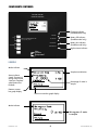
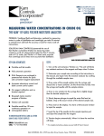
KAM® KF KARL FISCHER MOISTURE ANALYZER
USER MANUAL
PER ISO 12937, ASTM D 4928,
API MPMS 10.9, ISO 12937, IP 386
REV. 0112
KAM CONTROLS, INC.
3939 Ann Arbor Drive
Houston, Texas USA 77063
T: +1 713 784 0000
F: +1 713 784 0001
www.KAM.com
KAM CONTROLS is an ISO 9001 certified company.
KAM CONTROLS, INC. reserves the right to make changes to this document without notice.
TABLE OF CONTENTS
SECTIONTITLEPAGE
1 Introduction 2
•Available models 2
•Theory of operation
2
2 Specifications
3
3 Components
4
• Display panel 4
• Titration Cell assembly 6
• Side and Rear Panels 7
4
Operation 8
• Assembly 8
• Adding Reagent 9
• Blank elimination operation 9
• Moisture content determination
10
• Sample dilution 11
5
Maintenance
12
• Reagent replacement procedure
12
• Storage 13
• Special Grease 13
• Electrode cleaning procedures
13
6
Ordering information
15
KFMANUAL 0112
1
KAM CONTROLS, INC.
INTRODUCTION
AVAILABLE MODELS and ACCESSORIES
KAM® LKF Karl Fischer Moisture Analyzer Lab Model
KAM® PKF Karl Fischer Moisture Analyzer Portable Model
KAM® Homogenizer
(For a full list of consumables, accessories, and parts, see page 15)
THEORY OF OPERATION
KAM Moisture Analyzers incorporate the coulometry principle applied to Karl Fischer titration to totally eliminate
the troublesome procedures involved in conventional water determinations. Available in a lab model as well as a
portable, KAM Moisture Analyzers are easy to use and fully automatic. The Portable Model has a rugged case
for field water determinations and the capability to operate continuously for 10 hours before needing recharging.
Incorporating a special electrolysis current control system, Moisture Analyzers assure fast, accurate measurement
of even trace content.
KAM Moisture Analyzers can be used to rapidly and accurately determine the water content of liquid hydrocarbons for all custody transfer operations: pipeline, marine, or truck movement. The Moisture Analyzer can also be
used to analyze crude oils, distillates, transformer oils, jet fuels, chemicals, and most other liquids. In the plant, it
can monitor the moisture content of streams during start-ups, shutdowns, upsets, and normal operations. This can
be especially important on units where expensive catalysts can be damaged by excessive moisture. The
unit also can be used by machinists as part of a preventive maintenance program. By analyzing lube oil on
compressors, turbines, etc., the Moisture Analyzer can detect cooling water leaks before they become severe
enough to damage equipment.
Karl Fischer titrimetry is an accurate moisture measurement method utilizing the quantitative reaction of water with
iodine. This method is the standard method of moisture measurement because of its speed and high sensitivity. In
coulometric Karl Fischer titration, the sample is added to the Karl Fischer Reagent (iodine ion and sulfur dioxide as
principal components). Iodine, generated electrolytically at the anode, reacts with water in the sample as shown in
Formula 1. Iodine is generated in direct proportion to the quantity of electricity according to Faraday’s Law.
Formula 1: I2 + SO2 + H2O - 2HI + SO3
One mole of iodine reacts quantitatively to one mole of water; therefore, 1mg of water is equivalent to 10.71
coulombs (Formula 2). Based on this principle, water content can be directly determined from the quantity of
electricity required for electrolysis. This eliminates the need for addition of Reagent and tedious standardization
procedures.
Formula 2: 2I- - 2e- -I
KFMANUAL 0112
2
KAM CONTROLS, INC.
SPECIFICATIONS
SPECIFICATIONS
Method: Coulometric Karl Fischer titration, ASTM D 4928, API MPMS 10.9,
ISO 12937, IP 386
Detection: Polarization detection
Control: Automatic electrolysis current control
Sample Size: 0.1, 0.25, 0.5, 1.0 ml for direct reading of volume % H2O, or less than two grams (ml)
Range: 10 µg - 100,000 µg H2O (i.e. for a 100 µl sample, the direct display is 0.0010% to 10% H2O)
Sensitivity: 1 µg H2O
Precision: ±5 µg for 10 µg – 1000 µg
0.5% (C.V.) for over 1000 µg
(meets or exceeds API MPMS 10.9, ASTM D 4928, and IP 386)
Titration Speed: 1000 µg H2O/min. (max., at high H2O concentrations)
Power Requirements: Operates on either AC or DC. AC - 110/120, 220/240 V, 50/60Hz
DC - Rechargeable battery for portable model (12 - 14 V)
Dimensions: Approx. 15 (W) x 10 (L) x 9 (H) inches
Weight: Lab Model Approx. 10 pounds
Portable Model Approx. 20 pounds
KFMANUAL 0112
3
KAM CONTROLS, INC.
COMPONENTS
DISPLAY PANEL
C. ON (Titration)
The ON key has two functions: 1) It initiates the
flow or titration current which corresponds to the
moisture content in the sample. The titration current
flows until all of the moisture is consumed (titrated).
2) The ON key also functions as the magnetic stirrer start switch.
A. Microgram Mode
Press to initialize measurement of the
mass of water (in micrograms) in the
injected sample. The numerical display
will show the micrograms of water in
the sample from 0 to 99,999.
Note: Between titrations there will be some current
flow to balance accumulated moisture.
B. Volume Percentage Mode
Press once to initialize measurement of
the volume percentage of water in the
injected sample. Press repeatedly to
cycle through sample sizes to be
injected (percent mode 0.1, 0.25, 0.5,
or 1.0 ml; dilution mode 0.5 or 1.0 ml).
Selected size is displayed in the upper
right-hand corner of the LCD readout.
D. OFF (Titration)
Press to end titration and the operation of the
magnetic stirrer. The following operations require
that the titration has ceased and the magnetic
stirrer has stopped:
• Removing the cathode solution cell
• Removing the detector electrode
• Removing or gently swirling the generator
solution cell
• Adding or removing Generator Solution A or
Generator Solution C
For calculations of weight percent other
than 0.1, 0.25, 0.5, and 1.0 ml, please
refer to the API MPMS Chapter 10.9,
or the ASTM D4928.
E. RESET (titration)
Press to reset count to 0 and begin titration
KAM KARL FISCHER
MOISTURE ANALYZER
A. Microgram mode
CHARGING
µg
H2 O
%
B. Volume percentage mode
FULL BATTERY
PRESS TO CHANGE SAMPLE SIZE
1.0, 0.5, 0.25, 0.1 ML
LOW BATTERY
ON
C. On (titration)
D. Off (titration)
TITRATION
HIGH MOISTURE
OFF
RESET
Kam
Controls
Incorporated
®
E. Reset (titration)
KFMANUAL 0112
4
KAM CONTROLS, INC.
COMPONENTS CONTINUED
KAM KARL FISCHER
MOISTURE ANALYZER
CHARGING
µg
H2 O
%
FULL BATTERY
PRESS TO CHANGE SAMPLE SIZE
1.0, 0.5, 0.25, 0.1 ML
LOW BATTERY
ON
TITRATION
Battery full indicator
(Portable model only)
Battery low indicator
(Portable model only)
HIGH MOISTURE
OFF
RESET
Charging indicator
(Portable model only)
High moisture indicator
Kam
Controls
Incorporated
®
LCD DISPLAY
Mode indicator
Sample size indication
Status indicator
(reads “Processing”
during analysis and
“Analysis Complete”
when titration has
finished)
Detector current
bar graph display
Percentage of water in
sample
Titration current bar graph display
Mode indicator
Micrograms of water
in sample
KFMANUAL 0112
5
KAM CONTROLS, INC.
COMPONENTS CONTINUED
TITRATION CELL ASSEMBLY
Cathode Solution Cell
This cell is equipped with an
electrolysis electrode which has
two platinum screens separated
by a ceramic frit (membrane).
This is the cell that holds
Generator Solution C.
Drying Tube
Removes moisture from the
the atmosphere to the
Generator Solution Cell.
Detector Electrode
Detects the conductivity of the fluid
Septum
Sample Injection Port
Generator Solution Cell
with Glass Top
Holds the Generator Solution A
KFMANUAL 0112
Stir Bar
6
KAM CONTROLS, INC.
COMPONENTS CONTINUED
SIDE and REAR PANELS
Jack for the Detector Electrode
Insert the male plug for the Detector
Electrode in the jack marked DETECTOR
Power Plug
Stirring Speed
The stirring speed of the bar in
the cell is preset. If a slower or
faster stirring speed is
required, adjust the knob.
Stirring speed is automatically
corrected for varying viscosity.
Jack for the Cathode Solution Cell
Insert the male plug for the Cathode Solution
Cell in the jack marked TITRATION
KFMANUAL 0112
7
KAM CONTROLS, INC.
OPERATION
All Models: Before connecting the power cord to an AC power source, ensure power switch
on the Analyzer base is in the OFF position (press switch to the left).
Portable Models: The power cord is kept inside the top of the portable case. When the
Analyzer is operated on battery power, the power cord is not necessary. Plug the portable
unit in to recharge.
ASSEMBLY
1. Loosen the Hold Down Clamp (A) by
unscrewing the compression nut, and slide
it upwards until it rests at the bottom of the
Thumb Screws (B).
E
2. Slide the Generator Solution Cell (C)
through the Hold Down Clamp until it
rests on top of the Stirring Plate (D). Then
tighten the compression nut on the Hold
Down Clamp to secure the cell in place.
F
3. Prior to installation, apply a thin
layer of Special Grease to the tapered
joint of each piece of glassware in order
to ensure an air-tight, moisture-tight
Generator Solution Cell.
G
I
H
4. Insert the Cathode Solution Cell (E),
Detector Electrode (F) and Drying Tube
(G) into the appropriately sized holes in
the top of the Generator Solution Cell (C).
B
A
5. Place a Rubber Septum (H) beneath the
Sample Injection Port (I).
C
NOTE: Do NOT grease the Sample
Injection Port.
D
6. Insert the plug of the Cathode Cell (E) in
the jack labeled TITRATION (J)and the
plug of the Detector Electrode (F) into the
jack labeled DETECTOR (K).
K
NOTE: Orientation of the compression
nut can be reversed to accommodate left or
right-handed operation.
KFMANUAL 0112
J
8
KAM CONTROLS, INC.
OPERATION CONTINUED
ADDING REAGENT
1.
Remove the stopper connected to the drying tube from the Generator Solution Cell
and pour entire, premeasured contents of KAM Generator Solution A (P# 09004 in
a 100 ml bottle) into the Generator Solution Cell using the 55 mm funnel (enclosed).
After pouring the solution replace the stopper.
2.
Remove the stopper from the Cathode Solution Cell and pour entire, premeasured
contents of KAM Generator Solution C (P# 09006 in a 5 ml ampoule) into the Cathode
Solution Cell using the 35 mm funnel (enclosed). After pouring the solution, replace the
stopper.
NOTE: Wrap the Generator Solution C ampoule in a towel to break tip before pouring. KAM CONTROLS Reagents ship
already measured at the appropriate
volumes for Reagent replacement
Blank Elimination Operation
Each time new Reagents are added to the Cathode and Generator Solution Cells a blank
elimination must be performed to remove any residual moisture within the cells.
1.
Plug unit in and turn the Power Switch ON. When the Analyzer is energized, the digital
display reads “0.”
2.
Push the Titration ON key. The Stir Bar will begin rotating. Approximately 5 seconds
later, electrolysis current will flow. As the residual moisture in the cell decreases
because of the reaction with iodine, the detector potential also decreases. In
association with the detector potential, the electrolysis current decreases
proportionally. When the detector potential approaches the zero point, the electrolysis
current decreases to a level lower than 5 mA, where it finally comes into equilibrium
with the blank current. When the blank current becomes less than 1 mA, the
measurement is complete. The Analyzer is now ready for measurement.
KFMANUAL 0112
9
KAM CONTROLS, INC.
OPERATION CONTINUED
IN CASE OF A LARGE BLANK CURRENT
If moisture has collected within the inner area and on the inner wall of the Generator
Solution Cell, the blank current becomes larger than approximately 1 mA.
In this case, press the RESET button and the Titration OFF button. When the Stir Bar has
ceased rotation, remove the Generator Solution Cell and gently swirl the Generator
Solution around the sides of the Cell in order to allow any moisture inside the cell to be
absorbed by the Reagent. Remount the Generator Solution Cell on the cell holder and
restart electrolysis.
Once you have conducted this procedure a couple of times, the blank current decreases
gradually to near the zero point in most cases. If the blank current cannot be reduced to a
low level, the cause is a leakage of moisture from the atmosphere. In this case, a close
inspection of all joints and Silica Gel is recommended. If this does not work, try cleaning
and drying the Generator Solution Cell.
If the titration continues and never reaches an end point, the Generator Solution A and
the Generator Solution C are generally worn out. (Follow the steps on page 12 to replace
Reagent). The Analyzer is now ready for moisture content determinations.
MOISTURE CONTENT DETERMINATION
Sample preparation and methodology must conform to the standards dictated in API MPMS
Chapter 10.9.
1.
Prior to sample analysis ensure that:
• Titration ON key is pressed and the digital display for titration and detection
is operative
• The blank current is not fluctuating
• The Stir Bar is operating
2.
Determine the sample size. The standard moisture determination range for this
instrument is from 10 micrograms to 10 milligrams of water. In order to determine the
moisture content of the sample accurately and effectively, control the sample size
corresponding to the estimated moisture content of the sample. Use the following chart
to determine sample size:
ESTIMATED MOISTURE CONTENT
SAMPLE SIZE
1–100 µg or 0.0001%–0.0100%
1 ml
100–1000 µg or 0.0100%–0.1000%
0.1–1 ml
1000–10000 µg or 0.1000%–1.000%
0.01–0.1 ml
KFMANUAL 0112
10
KAM CONTROLS, INC.
OPERATION CONTINUED
3.
To draw a sample, first clean the syringe by rinsing the inside of the syringe barrel and
needle with the sample to be measured. Draw this sample into the syringe and
discharge the sample into a waste container at least three times.
4.
Draw a sample in to the syringe. The sample volume should be slightly larger than the
desired amount.
5.
Discharge air bubbles and excess sample fluid from the inside of the syringe by slowly
pushing the plunger to the desired sample size.
6.
Press RESET key to clear display to “0.”
7.
Insert syringe needle through the Sample Injection Port on the Generator Solution Cell,
ensuring that the needle tip is submerged in the Reagent.
8.
Inject the sample into the Reagent. Do not allow the sample to splash up against the
wall of the Generator Solution Cell or the needle to touch the sides of the cell.
9.
Electrolysis begins automatically by the injection of the sample. When the analysis is
completed, the buzzer sounds and the result is displayed on the digital readout and
can be recorded.
NOTE: Do not press RESET during titration or the instrument will fail to produce correct
data.
SAMPLE DILUTION
In cases where the viscosity of the sample is such that it cannot be pulled into a syringe or
when the anticipated water content is higher than 5%, users may dilute the sample
according to the following steps.
1.
Dilute (mix) the sample with a ratio of 1 part (1 ml) sample to 99 parts (99 ml) of
Reagent-grade xylene.
2.
The Analyzer automatically adjusts for the dilution factor based on the sample size
selected.
KFMANUAL 0112
11
KAM CONTROLS, INC.
MAINTENANCE
REAGENT REPLACEMENT PROCEDURE
API Chapter 10.9 Section 7 states that Reagents should be replaced after 7 days.
1.
Carefully remove the stoppers from the Generator and Cathode Solution Cells. Care
should be exercised not to damage the two electrode connections.
2.
With a suitable suction or aspirator device, remove the old solution from the Generator
and Cathode Solution compartments.
3.
Wipe all tapered glass joints (male and female) with clean tissue to remove the old
grease.
4.
Pour a 5 ml ampoule of Generator Solution C (P# 09006) into the Cathode (inner)
Solution Cell using the 35 mm funnel.
5.
Grease the glass stopper with Special Grease (P# 09015) and insert it into the seat on
the cell.
6.
Pour a 100 ml bottle of Generator Solution A (P# 09004) into the Generator Solution
Cell using the 55 mm funnel.
7.
Grease the detector and insert it into the seat on the cell.
8.
Insert Sample Injection Port (without grease) into the seat on the Generator Solution
Cell.
9.
Change the rubber septum (P# 09029) inside of the Sample Port.
10. Press the Titration ON button. Allow the residual moisture in the titration vessel to be
titrated until the end point is reached.
11. Do not proceed beyond this point until the titration end point is reached.
12. If the titration continues at a slow rate for a prolonged period, press the Titration OFF
button. Loosen the hold-down clamp on the Generator Solution Cell. Carefully remove
the cell and gently swirl it to remove any moisture from the sides of the vessel. Replace
the cell and tighten the hold-down clamp before resuming the titration. The end point
should then be reached very quickly.
13. Set the Analyzer to the g or % mode. The apparatus is now ready for sample analysis.
KFMANUAL 0112
12
KAM CONTROLS, INC.
MAINTENANCE CONTINUED
Storage
When the Analyzer is out of use for an extended period of time, do not disconnect any of
the attachments on the Generator Solution Cell. Keep all parts mounted to prevent moisture
absorption in the Reagents. If the cell is left standing with the drying tube removed the
ceramic frit on the Cathode Solution Cell will absorb moisture.
For storage over 2 weeks time, all glass needs to be washed cleaned and dried.
SPECIAL GREASE
To keep the Generator Solution Cell performing accurately and effectively be sure that a
thin layer of Special Grease is applied to all glass tapered joints (male and female) each
time the Reagents are replaced. Frequent greasing will prevent the glassware from
seizing and causing damage to the cell. The Special Grease does not absorb moisture, so it
will not hinder the results of the analysis. No other grease should be used with a KAM KF
Karl Fischer Moisture Analyzer due to the potential for the grease to absorb moisture and
interfere with titration if it is silicon based.
KAM CONTROLS is not responsible for problems resulting from the use of improper grease.
Electrode Cleaning Procedures
Dirty electrodes usually result in the following problems:
• A decrease in titration efficiency resulting in a longer measuring time
• An increase in the blank (residual) value of titration current due to absorption of moisture
in the dirty area
• Unstable titration current and lack of reproducible results
• Staining on the ceramic frit at the bottom of the Cathode Solution Cell
NOTE: This procedure uses Reagent grade nitric acid. Because nitric acid produces
corrosive fumes, be sure and conduct all parts of this procedure in an appropriately
ventilated environment.
Nitric acid should NOT be reused. Follow appropriate disposal procedures.
1.
Pour the contents from the Cathode Solution Cell and discard.
2.
Wipe the grease off the tapered joint with tissue paper wetted with acetone.
3.
Remove any exterior contamination with tissue paper and acetone being careful not
to damage the platinum wires and screen on the outside of the cell.
KFMANUAL 0112
13
KAM CONTROLS, INC.
MAINTENANCE CONTINUED
4.
Fill the Cathode Cell with acetone and stopper the inlet joint. Shake the unit until any
dirt is removed. This should be repeated several times. Pour out and discard acetone.
5.
Wash the outer surface with acetone.
6.
Pour approximately 5 ml of nitric acid into the Cathode Solution Cell.
7.
Place the cell in a 50 ml beaker and fill the beaker with nitric acid to the same level as
is in the cell. Secure the Cathode Solution Cell so that it will not fall over. Allow the cell
to remain in the solution overnight.
8.
After the cell has stood overnight, discard the nitric acid in the cell, and rinse the inside
and outside of the cell with running tap water until the yellow color disappears.
9.
Place distilled water in the cell and place it in a 400 ml beaker filed with distilled water.
10. Place the beaker on a hot plate and bring the water to a slow boil for at least one hour.
11. Repeat this operation until there is no coloration of the water.
12. Remove the Cathode Solution Cell from the water and fill it with acetone to overflowing,
flooding the outside of the cell as well. Repeat several times.
13. Dry the cell with a forced air dryer.
14. Place the entire assembly in a laboratory oven and continue to dry it for several hours
at 120ºF.
15. Fill the cell with Generator Solution C and reinstall in the Generator Solution Cell.
The Generator Solution Cell is cleaned in a similar manner minus the cleaning of the inside of
the probe.
KFMANUAL 0112
14
KAM CONTROLS, INC.
ORDERING INFORMATION
KAM KF KARL FISCHER MOISTURE ANALYZERS
P# 09031 KAM PKF PORTABLE KARL FISCHER MOISTURE ANALYZER: Battery powered
Analyzer includes Recharger (120 VAC), Titration Cell, Electrodes, Stir Bar, Drying Tube,
and Carrying Case.
P# 09042 KAM LKF LAB KARL FISCHER MOISTURE ANALYZER: includes Titration Cell,
Electrodes, Stir Bar, Drying Tube, and 120 VAC Power Adapter.
P# 09041 STARTER KIT: Contains all required items for analysis, including: Generator
Solution A, Generator Solution C, Calibration Verification Solution, 1 ml and 10 µl Gastight
Syringes with Needles, package of 100 Septums, 2 Funnels, Special Grease and Silica Gel.
SUPPLIES AND CONSUMABLES
STANDARD GENERATOR SOLUTIONS
P# 09004 GENERATOR SOLUTION A (Anode): pack of 6, 100 ml bottles
P# 09006 GENERATOR SOLUTION C (Cathode): pack of 6, 5 ml ampoules
P# 09032 CALIBRATION VERIFICATION CHECK SOLUTION: box of 10, 4 ml ampoules (1%
water content), certificate included
P# 09013 SILICA GEL: 100 ml bottle
GLASSWARE
P# 09052 COMPLETE TITRATION CELL ASSEMBLY: includes Generator Solution Cell,
Cathode Solution Cell, Detector Electrode, Drying Tube, Sample Injection Port, Stir Bar
P# 09064 DETECTOR ELECTRODE
P# 09063 CATHODE SOLUTION CELL
P# 09062 GENERATOR SOLUTION CELL
KFMANUAL 0112
15
KAM CONTROLS, INC.
ORDERING INFORMATION
SYRINGES AND NEEDLES
P# 09010 GASTIGHT SYRINGE, 10 µl
P# 09023 GASTIGHT SYRINGE, 50 µl
P# 09021 GASTIGHT SYRINGE, 250 µl
P# 09022 GASTIGHT SYRINGE, 500 µl
P# 09008 GASTIGHT SYRINGE, 1 ml
P# 09001 GASTIGHT SYRINGE, 2.5 ml
P# 09002 NEEDLE, 19-gauge, 4”
P# 09003 NEEDLE, 14-gauge, 4”
SPARE PARTS
P# 09049 SAMPLE INJECTION PORT
P# 09044 STIR BAR
P# 09050 DRYING TUBE
P# 09029 RUBBER SEPTUM, pack of 50
P# 09015 SPECIAL GREASE, 25 g tube
P# 370420 REPLACEMENT RECHARGEABLE BATTERY (for model 09031)
P# 370400 POWER ADAPTER, 110/120 or 220/240 VAC
ACCESSORIES
P# 09014 HOMOGENIZER DRIVE UNIT, 110/120 or 220/240 VAC with speed control
P# 09019 DISPERSING TOOL FOR HOMOGENIZER, 18 mm (for 50-2000 ml volume)
P# 09009 DISPERSING TOOL FOR HOMOGENIZER, 25 mm (for 500-4000 ml volume)
P# 09018 HOMOGENIZER STAND
KFMANUAL 0112
16
KAM CONTROLS, INC.