1
National Conference on Emerging Trends in Computer, Electrical & Electronics (ETCEE-2015)
International Journal of Advance Engineering and Research Development (IJAERD)
e-ISSN: 2348 - 4470 , print-ISSN:2348-6406,Impact Factor:3.134
The Query: The function code in the query informs the
addressed slave device what kind of action to be performed.
For examp le, if the function code 03 will query the slave to
read holding registers and respond with their contents. The
data field must contain the in formation telling the slave which
register to start at and how many registers to read. The error
check field provides a method for the slave to validate the
integrity of the message contents [2].
The Response: If the slave responds normally, the function
code in the response is an echo of the function code in the
query. The data bytes contain the data that is collected by the
slave, such as register values. If any error occurs, the function
code is modified and also indicates that the response is an
error response, and the data bytes contain a code that
describes the error. The error check field allows the master to
confirm that the message contents are valid [2].
B. The Serial Transmission Modes
Modbus networks using either of two transmission modes:
ASCII or RTU. Users select the desired mode, along with the
serial port co mmunication parameters (baud rate, parity mode,
etc.), during configuration of each controller. The mode and
serial parameters must be the same fo r all devices on a
Modbus network [2].
1) ASCII : When controllers are setup to communicate on a
Modbus network using ASCII (A merican Standard Code
for Info rmation Interchange) mode, each 8–bit byte in a
message is sent as two ASCII characters. The main
advantage of this mode is that it allows time intervals of
up to one second to occur between characters without
causing an error [2].
Character density allows better data throughput than ASCII
for the same baud rate. Each message must be transmitted in a
continuous stream [2].
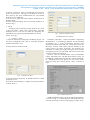
TABLE II
The format for each byte in RTU mode
C. Function code used in MODBUS Protocol
TABLE III
Function Code of Modbus
TABLE I
The format for each byte in ASCII mode
D. MODBUS Data model
TABLE IV
Modbus data model
2) RTU: When controllers are setup to communicate on a
Modbus network using RTU (Remote Terminal Un it) mode,
each 8–bit byte in a message contains two 4–bit hexadecimal
characters. The main advantage of this mode is that it‘s
greater
III. M ODBUS IN PLC
M icro830
controllers
support
the
follo wing
communicat ion protocols through the embedded RS-232/RS-