1
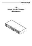
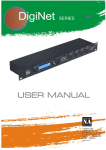
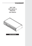
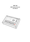
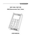
XPD-28 2:8 DMX & RDM Splitter User Manual 2 UM_XPD-28-D0-LEN-V01-00.DOCX 2015-10-26 Index Index.................................................................................................................................................................................. 3 Introduction ...................................................................................................................................................................... 4 Unpacking ......................................................................................................................................................................... 5 Safety Information ............................................................................................................................................................ 5 Device Overview ............................................................................................................................................................... 7 Settings and Menu ............................................................................................................................................................ 9 Status LEDs ...................................................................................................................................................................... 13 Screen Saver .................................................................................................................................................................... 14 DMX Input Monitoring and Diagnostics.......................................................................................................................... 14 RDM ................................................................................................................................................................................ 14 Firmware Updates........................................................................................................................................................... 14 Technical Data ................................................................................................................................................................. 15 Ordering Information ...................................................................................................................................................... 16 3 Introduction XPD-28 is a DMX & RDM splitter provided with eight outputs, which can be connected to any of the two inputs. Each of its ten signal ports is optically isolated. With its 128x64 pixels OLED display, an encoder and a push button for each of the signal ports, the configuration of the splitter is quick and easy to do in spite of the device’s versatility. An RGB LED next to each of the signal ports lets you know at a glance whether a good signal is available at any given port. If you need to know more about the incoming DMX signal, the OLED display will show you the refresh rate and the number of received channels when you push the button next to any of the two inputs. Furthermore, a graphical overview of the received channel values is available. The various output modes of the XPD-28 also allow for using the device as an accelerator or decelerator. The XPD-28 is available with 3-pin or 5-pin XLR connectors or with Neutrik etherCON RJ45 connectors. Applications Concert lighting Live events Multimedia shows Theaters TV studios Theme parks Architectural lighting Typical Application 4 Unpacking The XPD-28 is packaged in a cardboard box. The following items are included: The device. This user manual. Safety Information Consider the following notes mandatory when you set up, connect and use the XPD-28. This product is approved for professional use only, it is not intended for household usage. Read this manual before operating the device, follow the safety precautions closely and pay attention to all warnings given in this manual. Use this device only in accordance with local laws and regulations. Safety Precautions Disconnect the device from the AC power supply before removing any cover or part, including fuses, even when not in use. Ensure that the device is electrically connected to ground (earth). Use only a source of AC power supply that complies with local building and electrical regulations and which has both overload and ground-fault (earth fault) protection. Before using the device, check that the power distribution equipment and cables are in perfect condition and rated for the current required by all connected devices. Isolate the device from power supply immediately if the power cable or the power plug are in any way damaged, defective or wet, or if they show signs of overheating. Do not expose the device to rain or moisture. Do not operate the device if any cover or component is missing, damaged or deformed. Refer any service operation not described in this manual to Swisson. Provide unrestricted airflow around the device. Do not operate the device if the ambient temperature exceeds 55°C (131°F). Do not modify the device in any way not described in this manual or install other than genuine Swisson parts. Do not attempt to bypass any fuse. Replace any defective fuse with one of the specified type and rating only. When suspending the device, ensure that the supporting structure and all hardware used can hold at least 10 times the weight of all devices suspended together. When suspending the device, install a secondary attachment such as a safety cable that is approved by an official body such as, e.g. TÜV (German Technical Monitoring Association), a safety attachment for the total weight it secures. The safety cable must comply with EN 5 60598-2-17 section 17.6.6 and be capable of bearing a static suspended load 10 times the weight of the device. Make sure that any external cover and rigging hardware is securely fastened. Provide an adequate clearance underneath the work area and a stable platform whenever installing, servicing or moving an overhead device. Do not use the device in areas where it is exposed to direct sunlight. Do not use the device in areas that are considered to be “highly inflammable”. 6 Device Overview 1. OLED display. 2. Encoder wheel / [OK] button. The encoder is primarily used for selecting menu items by turning the knob. It also functions as a push button. This manual refers to this button simply as [OK] button or [OK]. 3. [Cancel] button. 4. Input port buttons [A] and [B]. These push buttons are used to display detailed status information of the respective input. An input port status LED showing essential, basic status information, is located directly below each of those buttons. 5. Signal input ports for the universes A and B. 6. Output port buttons [1] – [8]. These push buttons are used to change to which universe the respective output is connected. An output port status LED showing to which universe the respective output port is currently connected as well as further status information is located directly below each of those buttons. 7. Signal output ports 1 – 8. 8. Neutrik powerCON input socket. 9. Neutrik powerCON output socket. 10. Type B USB socket for firmware updates. Mains Connection The user must supply a suitable power cable. He may then either hard-wire the power cable to the building’s electrical installation, providing an easily accessible power on/off switch close to the device, or install on the power cable a grounding-type (earthed) mains plug that is suitable for the local power outlets, following the power plug manufacturer’s instructions. Consult a qualified electrician, if you have any doubts about the proper installation. A blue Neutrik powerCON NAC3FCA cable mount connector must be used to supply power at the XPD-28’s power input socket. Warning! For protection against dangerous electrical shocks, the device must be grounded (earthed). The local AC power source must be supplied with both overload and ground-fault (earth fault) protection. 7 Important! Only attach or remove a Neutrik powerCON connector while it is connected to the mains to apply or cut power in an emergency situation, as by doing so may cause arcing at the terminals that will damage the connectors. Power Outlet Warning! The total current load of all devices connected to the AC mains power outlet of the XPD-28 must not exceed 19.8 amperes. • A power cable that meets the requirements specified in the safety instructions section of this manual must be used to connect the XPD-28 to AC mains power and to connect other devices to the power outlet. • A light-grey Neutrik powerCON NAC3FCB cable-mount connector must be used to draw AC mains power from the XPD-28’s power outlet. • No matter what the AC mains power voltage is, the current drawn by all the devices that draw AC mains power from the power outlet of an XPD-28 must not exceed a total of 19.8 amperes. DMX Connections Depending on the version, the XPD-28 is equipped with 5-pin or 3-pin XLR connectors or with Neutrik etherCON RJ45 connectors. XLR Connectors Pin 1 2 3 4 5 Connection Com Data Data + Not connected Not connected 5 1 2 3 4 5-Pin XLR male (DMX in) 5 4 3 1 2 5-Pin XLR female (DMX out) 1 2 2 1 3 3 3-Pin XLR male (DMX in) 3-Pin XLR female (DMX out) RJ-45 Connectors Pin 1 2 3 4 5 6 7 8 Shield Connection Data + Data Not connected Not connected Not connected Not connected Com Com Earth The DMX inputs are fully isolated and have a built-in termination. All outputs are isolated transmitters with a bias network for RDM operation. Each output port is individually optically isolated, meaning that it is totally isolated from the other output ports and from the input section. 8 Settings and Menu General Navigation The encoder wheel (see page 7) is the primary means for navigating through the menus. Most of the menus arrange items vertically. In those menus, turn the encoder clockwise to select the item below the currently selected item or turn the encoder counter clockwise to select the item above the currently selected item. In menus that arrange items horizontally (e.g. text fields), clockwise means “to the right” and counter clockwise means “to the left”. Other than that, the encoder wheel also functions as a push button. This button is generally used to confirm a selection or to navigate to a selected submenu. This manual will also refer to pushing the encoder knob as “push [OK]” or “push the [OK] button”. On the right side of the encoder knob you can find the [Cancel] button (depicted on page 7), which is generally used to dismiss a selection or to exit a menu. By keeping the [Cancel] button pressed for at least two seconds, you can always navigate to the Home Screen. From the Home Screen, the menu is launched by simply pushing the [OK] button. Below, the following notation is used to describe locations in the menu: Home > Menu > Sub menu > … For example, the manual could say “navigate to Home > Menu > Input A > Mode”. This can be read as follows: Keep [Cancel] pressed for 2 seconds to reach the Home Screen. Then, press [OK] to get to the menu. Select “Input A” using the encoder wheel and press [OK] again to confirm the selection. Select “Mode” and confirm your selection once more with the [OK] button. Home Screen Home Screen indicating that no signal is applied available on either of input to either the port. input ports. Home Screen indicating that a valid signal is applied to each of the signal inputs. 9 Home Screen showing a valid signal on input A and a disturbed signal on input B. The Home Screen (Main Screen) is divided into a left and a right section. The left section contains information about the signal status of the input A and the currently active DMX Output Mode (see page 11) of the outputs connected to input A. The other half of the Home Screen shows the same information for the input port B and its connected outputs. Input / Universe Settings and Information The settings for the universe A (B) and its input are accessible under Home > Menu > Input A (Home > Menu > Input B). This menu offers the sub menus “Mode”, “Failure Behaviour” and “Status Information”, which are described next. DMX Mode The DMX mode of the outputs connected to universe A (B) can be selected under Home > Menu > Input A > Mode (Home > Menu > Input B > Mode). A mode is activated by selecting it using the encoder and confirming the selection with the [OK] button. The currently active mode is flagged by a bullet point on the left side. The following modes are available: DMX and RDM In this mode, any arriving DMX and RDM data is forwarded to the outputs of the corresponding universe as it arrives at the input. XPD-28 is discoverable via RDM and responds to RDM packets addressed to the device. For RDM-traffic addressed to devices connected to the outputs of the universe, the device operates as a bidirectional RDM-splitter. DMX and RDM is the default mode which is applied to both universes when you restore the default settings as described on page 13. Classic DMX DMX data is forwarded as it arrives. The splitter is not discoverable via RDM and does not work as a bidirectional splitter. DMX 40 Hz, Frame Int. This mode sends DMX data with a well-defined timing characteristic, regardless of the timing of the received signal. At the cost of a small delay, the “Frame Integrity” is maintained. This means, that no partially updated DMX frames are sent out. This may be important when multi-slot parameters are in use. The splitter is not discoverable via RDM and does not work as a bidirectional splitter. DMX 30 Hz, Frame Int. As above. DMX 20 Hz, Frame Int. As above. DMX 10 Hz, Frame Int. As above. DMX 40 Hz This mode sends DMX data with a well-defined timing characteristic, regardless of the timing of the received signal. The “Frame Integrity” is not maintained. This means that partially updated DMX frames may be sent out. The splitter is not discoverable via RDM and does not work as a bidirectional splitter. DMX 30 Hz As above. DMX 20 Hz As above. 10 DMX 10 Hz As above. Failure Behaviour For each of the two input universes, one of two failure behaviours can be chosen under Menu > Input A > Failure Behaviour (Home > Menu > Input B > Failure Behaviour). The failure behaviour determines how the respective universe reacts at the occurrence of a failure. Generally, it is considered a failure when no valid DMX signal is observed at the input for the duration of one second. If the universe is in DMX and RDM mode however, it is considered a failure only if neither a valid DMX frame nor the beginning of an RDM message is observed for one second. Off No DMX is sent on the outputs. In the modes DMX and RDM and Classic DMX the outputs continue to forward whatever arrives at the inputs. Hold Last Look The outputs of the universe continue sending out the last received look. If no data has been received before, no data is sent to the outputs. Status Information Status information about each of the inputs is accessible under Home > Menu > Input A > Status Information (Home > Menu > Input B > Status Information). As a shortcut, the button on the left below the respective input port can also be used to recall this information. Further details about this menu are explained on page 14 under DMX Input Monitoring and Diagnostics. Output Settings and Information Linking Outputs to Inputs Output ports can be linked to one of the two inputs under Home > Menu > Output N, where N stands for the number of the output. The number of each output is printed on the left above each XLR (or etherCON) output port. As a shortcut, the button on the left below each output port (button [1] – button [8]) can be used to access the same menu. From the menu depicted above, the encoder wheel or the button on the left below the output port can be used to change the universe to which the output port is connected. DMX Output Mode The DMX output mode is configured per universe. See DMX Mode on page 10. Failure Behaviour The failure behaviour is configured per universe. See Failure Behaviour above, under Input / Universe Settings and Information. Device Settings and Information Label The device label can be viewed and edited under Home > Settings > Label. 11 Deleting Text In order to delete a text line or a part of it, position the cursor immediately to the left of the first character you want to have deleted. Then keep [OK] pressed and turn the encoder clockwise until all of the text that you wish to delete appears highlighted. As you release the [OK] button, the highlighted text is removed. Inserting or Appending Text To append or insert text, move the cursor to the position where you want to add your text. Then push the [OK] button and select a character to add. Confirm your selection by pressing [OK]. Repeat the above steps for the remaining characters. Then, press [Cancel] to finish editing. Press [Cancel] again to quit the editor. 12 Press [OK] to store the changes or press [Cancel] to discard all changes. Information The following information about the device is available under Home > Menu > Settings > Information. Model The device model is reported as “XPD-28” for all variants of the XPD-28. UID (A) and UID (B) The RDM Unique Identifier for each of the universes. Boot Software The full version number of the boot software. Firmware The full version number of the firmware. Hardware The hardware revision. Restore Default Settings The default settings can be restored under Home > Menu > Restore Default Settings. In this menu, you will be asked whether you want to continue restoring all settings. Push [OK] to confirm or [Cancel] to abort. This function will restore all settings to the defaults: - Device label: XPD-28 - DMX mode: DMX and RDM (on both universes) - Failure behaviour: Off (on both universes) - Ports assigned to input A: 1-4 - Ports assigned to input B: 5-8 Status LEDs Selected Port When a port is selected, either with the push button next to it or via the menu, the port’s status LED flashes up in the colour of its universe for 0.1 seconds once every 0.2 seconds. The colour of the universe is amber for the universe A and blue for the universe B. Not Selected Port If a port is not selected, the port’s status LED provides the following information: It lights up in the colour of its universe for at least 50% of the time. Amber for universe A and blue for universe B. It turns black for 0.1 seconds every second, if at the port no signal is available. 13 It turns white for 0.4 seconds once a second, if the port’s universe has received the command to “identify” itself via RDM. It turns red for 0.1 second every second, when the port has received a faulty signal. (Input ports only) Screen Saver The OLED display will automatically turn itself off when no user input is received for 40 seconds in order to improve the durability of the product. Once the display is turned off, it can be turned on again by pushing any button or by turning the encoder wheel by one unit in any direction. DMX Input Monitoring and Diagnostics RDM XPD-28 is discoverable via RDM and works as an RDM capable, bidirectional splitter, when the corresponding universe is configured to the mode “DMX and RDM” (see DMX Mode on page 10). When a different mode is selected, the RDM capabilities of the splitter are disabled for the respective universe. Firmware Updates Firmware updates will be provided on the product page on the Swisson website. For updating the firmware, a PC with Windows (Vista or later) and a USB A to B cable (USB printer cable) is required. Please refer to the separate documentation also provided on the product web page for details about the process of updating the product’s firmware. 14 Technical Data Depth ........................................................................................... 136 mm (5.35 in) Width ........................................................................................... 482.6 mm (19 in) Height ........................................................................................... 44.5 mm (1.75 in) Weight .......................................................................................... 1.7 kg (3.75 lb.) Ambient temperature .................................................................. -30°C…55°C (-22°F…131°F) AC power ...................................................................................... 100 - 240 V nominal, 50/60 Hz Typical power consumption ......................................................... 9 W DMX.............................................................................................. ANSI E1.11 RDM ............................................................................................. ANSI E1.20 Electrical standard signal ports .................................................... EIA-485 15 Ordering Information Standard Versions 10 40 10 XPD-28-5R 2:8 DMX & RDM splitter, rack mountable, 5-pin XLR 10 40 11 XPD-28-3R 2:8 DMX & RDM splitter, rack mountable, 3-pin XLR 10 40 12 XPD-28-8R 2:8 DMX & RDM splitter, rack mountable, RJ45 Special Versions 10 40 13 XPD-28-5R8 2:8 DMX & RDM splitter, rack mountable, inputs: 5-pin XLR, outputs: 3-pin XLR 10 40 14 XPD-28-5R2 2:8 DMX & RDM splitter, rack mountable, inputs: 5-pin XLR, outputs: 6 x 5-pin XLR, 2 x 3-pin XLR 10 40 15 XPD-28-5R4 2:8 DMX & RDM splitter, rack mountable, inputs: 5-pin XLR, outputs: 4 x 5-pin XLR, 4 x 3-pin XLR 10 40 16 XPD-28-5R6 2:8 DMX & RDM splitter, rack mountable, inputs: 5-pin XLR, outputs: 2 x 5-pin XLR, 6 x 3-pin XLR 16