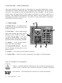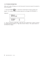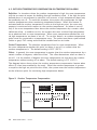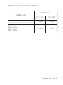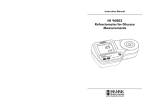
1
ALARM SYSTEM USERS MANUAL R05 Manufacturer: Viatron Electronics 3514 1st Street, St-Hubert (Quebec) Canada J3Y 8Y5 WARNINGS the warranty can be void if the Agri-Alert 2400 is used in a manner not specified by the manufacturer. Every effort has been made to ensure that this manual is complete, accurate and up-to-date. The information contained in it is however subject to change without notice due to further developments. 2 AGRI-ALERT 2400 - rev.05 Table of Contents CHAPTER ONE : USER INTERFACE ............................................................ 6 1.1 1.2 1.3 1.4 1.5 1.6 1.7 1.8 1.9 FRONT PANEL .................................................................................................. 6 MEANING OF STATUS LEDS .............................................................................. 7 DISPLAYING A PARAMETER .............................................................................. 7 MODIFYING A PARAMETER ............................................................................... 8 HOW TO USE THE MENUS ................................................................................ 9 SYSTEM MESSAGES ....................................................................................... 10 BURGLAR ZONES ............................................................................................ 10 ACKNOWLEDGING AN ALARM ......................................................................... 11 TELEPHONE INTERFACE ................................................................................... 12 CHAPTER TWO: SYSTEM INITIALIZATION .............................................. 16 2.1 POWER UP ..................................................................................................... 16 2.2 SYSTEM CLOCK ............................................................................................. 16 2.3 USER ID MESSAGE ......................................................................................... 18 2.4 PASSWORD PROTECTION ................................................................................ 20 2.4.1 Modifying the Master Password ............................................................ 20 2.4.2 Enabling / Disabling the Password Feature ............................................. 22 2.4.3 Modifying the User Passwords .............................................................. 23 2.4.4 Erasing All User Passwords .................................................................. 24 2.5 TEMPERATURE UNITS ..................................................................................... 25 2.6 POWER FAILURE ALARM ................................................................................. 26 2.7 TEST PROCEDURE .......................................................................................... 27 2.8 TROUBLE INFORMATION .................................................................................. 28 2.9 STANDBY MODE ............................................................................................. 29 CHAPTER THREE: COMMUNICATION PARAMETERS ................................. 30 3.1 INTRODUCTION .............................................................................................. 30 3.2 DIALING INFORMATION ................................................................................... 32 3.2.1 Busy Line Tries ................................................................................... 32 3.2.2 Message Repetitions ........................................................................... 32 3.2.3 Call Start Delay .................................................................................. 32 3.2.4 Time Between Calls ............................................................................ 32 3.2.5 Restore Calls ...................................................................................... 33 3.2.6 # of Call Repetitions ............................................................................ 33 3.2.7 Alarm Recall Time .............................................................................. 33 3.2.8 Pause Delay ....................................................................................... 33 3.3 PHONE NUMBERS ........................................................................................... 34 3.4 PULSE / TONE ................................................................................................. 38 3.5 ON SITE LISTENING ......................................................................................... 38 3.6 RINGS / ANSWERING MACHINE ........................................................................ 40 AGRI-ALERT 2400 - rev.05 3 CHAPTER FOUR: ALARM PARAMETERS .................................................. 42 4.1 ALARM VALIDATION: SUMMARY OF EVENTS ................................................... 42 4.2 SYSTEM ALARMS ........................................................................................... 43 4.3 OUTDOOR TEMPERATURE COMPENSATION ON TEMPERATURE ALARMS ............. 44 4.4 ALARM MEMORY ............................................................................................ 48 4.5 ZONE STATUS DISPLAY ................................................................................... 49 4.5.1 Viewing and Modifying Dry Contact Zones ............................................. 49 4.5.2 Viewing and Modifying Temperature Zones ............................................ 50 4.5.3 Viewing and Modifying Pulse Count Zones ............................................. 53 4.6 PARTITIONS ................................................................................................... 55 4.7 BYPASS / ACTIVATE FUNCTION ....................................................................... 57 4.8 ENTRY DELAY ................................................................................................ 59 4.9 EXIT DELAY .................................................................................................... 60 4.10 SIREN DELAY ................................................................................................ 61 4.11 RELAY OUTPUTS ........................................................................................... 62 TROUBLESHOOTING GUIDE .................................................................... 63 APPENDIX A: FUSE TYPES .................................................................... 65 APPENDIX B: MAXIMUM WIRE LENGTHS ................................................ 66 APPENDIX C: BACKUP BATTERY LIFE SPAN ............................................ 67 GLOSSARY OF TERMS ........................................................................... 68 WIRING DIAGRAMS ............................................................................... 70 TECHNICAL SPECIFICATIONS ................................................................. 72 REGISTRATION CARD ............................................................................ 73 4 AGRI-ALERT 2400 - rev.05 LIST OF TABLES AND FIGURES Figure Figure Figure Figure Figure 1: 2: 3: 4: 5: Calling a Pager Number ..................................................................... 37 Outdoor Temperature Compensation ................................................... 44 Critical Temperature Monitoring ......................................................... 45 Monitoring the Indoor-Outdoor Temperature Difference ......................... 45 Example of Partitioning ...................................................................... 55 Table 1: Pager Codes Used by the Agri-Alert System .......................................... 36 Table 2: System Alarms .................................................................................. 43 AGRI-ALERT 2400 - rev.05 5 CHAPTER ONE : USER INTERFACE The system displays and prompts for information by using the alphanumeric screen. The keypad is used for data entry and for enabling and disabling the various system functions. The speaker on the front panel delivers voice messages. A built-in piezoelectric warns of illegal entries (3 short beeps) and beeps once when a valid key is pressed. The integrated microphone on the front panel is used to record the user ID message and provide on-site listening. The status of some subsystems is displayed using LEDs on the front panel. 1.1 FRONT PANEL 1 - Display Screen — An alphanumeric display used to provide information and prompt for inputs. 2 - Cursor Keys — Used to step through menu items during data entry and for deleting the last character entered. 3 - Zone Status LEDs — Off: DISABLED; On: ACTIVATED; Slow Blinking: BYPASSED; Fast Blinking: ALARM. 4 - Speaker — Vocal system identification and alarm messages. 5 - Integrated Microphone — Records the ID message and provides on-site listening input. 6 - Keypad — User inputs and information requests. 7 - System LEDs — Status of various subsystems (see table on following page). KEYS TO SYMBOLS IN THE MANUAL ! WARNING Caution. Carefully read the following text for it contains important information which, if ignored, may cause the controller to operate improperly. Pay attention. The following text contains very useful information. 6 AGRI-ALERT 2400 - rev.05 1.2 MEANING OF STATUS LEDS L ED MEA N I N G A L A RM This LED is a ctiva ted when one or more a la rm cond itions a re d etected . The ind ivid ua l zone LEDs on the left sid e of the p a nel corresp ond ing to the zones in a la rm sta rt b linking a t hig h sp eed . The LED is turned off when the a la rm is a cknowled g ed a s long a s the a la rm cond ition no long er exists, the reset time ha s ela p sed a nd no other a la rms a re a ctive. S TA N D B Y This LED is a ctiva ted when the A g ri- A lert system is in sta nd b y mod e. In this mod e, the system stop s monitoring the sensor inp uts for a la rm cond itions. The LED is turned off when norma l monitoring is resumed . B Y PA S S This LED is a ctiva ted when one or more zones a re b yp a ssed . The ind ivid ua l zone LEDS on the left sid e of the p a nel corresp ond ing to the b yp a ssed zones sta rt b linking a t low sp eed . The LED is turned off when no zones a re currently b yp a ssed . RE CO RD This LED is a ctiva ted when the User ID messa g e is b eing record ed . P O WER FA I L U RE This LED is a ctiva ted when a p ower fa ilure is d etected on the 16VA C sup p ly circuit (wa ll mount tra nsformer). LO W B A T T E RY This LED is a ctiva ted when the b a ck- up b a ttery volta g e is low. FUS E This LED is a ctiva ted when a b lown fuse is d etected on a circuit. See a p p end ix for fuse typ es a nd loca tions. T RO U B L E This LED is a ctiva ted when: - a zone config ura tion conflicts with the sig na l received from the sensor - a wire short or op en circuit is d etected on a temp era ture or d ry conta ct with EOLR inp ut. - a wire op en or short is d etected on a 4- 20mA inp ut. - a softwa re p rob lem is d etected . 1.3 DISPLAYING A PARAMETER When you select a parameter to input or modify, the system begins by displaying the current value or status of the parameter. If the message to display is longer than the size of the window, it will be scrolled to the left. The display pauses at the end of each screen to allow time to read the message. You can exit prematurely from a display sequence at any time by pressing the Cancel key. This will place you in program mode and allow you to modify the parameter values (see next section). To exit from this function as well, press the Cancel key once again. AGRI-ALERT 2400 - rev.05 7 If a parameter is not completely defined when you try to display it, the message INCOMPLETE DATA appears on the screen. This may be an indication that the system will not behave as expected. If, for example, a zone input is not completely configured, the system will not monitor the zone for alarm conditions. Before enabling the system for normal operation, make sure all parameters are properly defined. In the case of phone numbers and zones, the system will display a message every 3 seconds telling the user which zones and phone numbers are incomplete. To exit from the warning display, press the Cancel key. 1.4 MODIFYING A PARAMETER If you have selected a parameter and the display sequence is now finished, you can begin modifying the parameter values. The following screen appears on the display: TO MODIFY. . . . . (↵) TO QUIT. . . . . . . (X) This screen is also displayed if the display sequence described above was cancelled prematurely. If you want to modify the parameter values at this point, press the Enter key to modify the parameter. The system will prompt for the information re- quired to define the parameter. When the parameter is defined by a numerical value, a range of possible values is displayed. For example, if you select the Exit Delay parameter followed by MODIFY, the system responds: RANGE FROM (0 .. 5 MIN, 0 .. 59 SEC) ENTER NEW DELAY _ MIN: _ _ SEC The number of spaces provided for input corresponds to the maximum number of digits allowed. In this example, one space is provided for the minutes and 2 spaces are provided for the seconds. The cursor positions itself on the first space and blinks until a digit is entered. If no response is given within 2 minutes, the system will cancel the input session and return to the Date/Time display. If more than one value is required in the same screen (in this example: hours and minutes), press Enter after entering the first value to step to the following one. To enter a zero value, you cannot simply press Enter; you must type 0 Enter. If you make a typing mistake, you can backstep using the back arrow key under- neath the display window before pressing Enter. The cursor will position itself accord8 AGRI-ALERT 2400 - rev.05 ingly. You can enter a negative value if this is allowed (for example, a negative temperature value) by pressing the +/- key either before or after the digits. After entering a value using the numerical keypad, press Enter to register the value. If the value entered falls outside the permissible range for that parameter, the system will beep three times and wait for you to modify the input using the back arrow key. 1.5 HOW TO USE THE MENUS Menus are used to select a parameter or to assign a predetermined value to a parameter. If the menu is comprised of only two items, they are displayed on the screen at once. For example, when you press the Clock key Clock , followed by Enter to modify, the following menu appears: QZ- DATE . . . . . . . . . TIME . . . . . . . . . (1) (2) You simply type the number of the item to select that item (no need to press the Enter key). When more than two menu items are involved, the system will display one item at a time and allow the user to scroll through the menu using the up and down-arrow keys . Each menu item is followed by an arrow symbol to locate the current position in the menu. Once a menu item is selected, other sub-menus may appear to further define the input. For example, if you press the Password key . After having entered the master’s password, the following sub-menu appears: PASSWORD STATUS The first menu item is STATUS. The arrow following the item means you are at the top of the menu. If you press the down-arrow , the second item appears: PASSWORD MASTER The arrows indicate that menu items are to be found above and below the current item. When you reach the end of the menu, the last item will have an up-arrow . To select a menu item, press Enter. AGRI-ALERT 2400 - rev.05 9 1.6 SYSTEM MESSAGES When the display is not being used by the user, the system periodically scrolls various status messages. If temperature zones are defined, the temperatures for those zones are displayed, as well as the low set point (L), the high set point (H) (the critical temperature (C) is also displayed if the outdoor compensation feature is enabled). When alarms are detected, they are displayed as well, including system alarms such as a battery failure or an unusual system temperature. When a zone or phone number is improperly configured, it is identified along with the message “INCOMPLETE DATA”. When burglar zones are armed, the message “BURGLAR ZONES ARMED” is displayed. If the system clock has never been adjusted, the message “ADJUST CLOCK” is displayed. Pressing any key will stop the display sequence. ZONE #3 L50 , H90 , 75.0oF C104 1.7 BURGLAR ZONES These zones are armed or disarmed as a group using a password. Two types of configurations are possible depending on when alarms are to be declared. In an instant burglar zone, alarms are declared as soon as they are detected. In a delay burglar zone, alarms are declared only after an Entry Delay has elapsed. In this way, the authorized user has time to disarm the burglar zones before an alarm is declared. This delay is common to all delay burglar zones. Similarly, all zones are armed after the Exit Delay has elapsed. The key sequence for arming or disarming is as follows: followed by the password sequence . When the system is armed, the system starts beeping and the screen immediately displays a countdown of the exit delay (in minutes and seconds). The keypad is locked at this point: the only key sequence allowed is the disarming sequence. After the exit delay has elapsed, the system is armed and alarms are immediately declared as they are detected for all burglar zones. The system displays the message “BURGLAR ZONES ARMED” periodically on the screen. When an alarm occurs in a burglar zone with an entry delay, the screen displays a countdown of the entry delay. During this time, the piezoelectric loudspeaker beeps (the loudspeaker stops when the key sequence is entered). If no one has disarmed the system after the entry delay has elapsed, an alarm is declared. Disarming will affect all currently active burglar zones. The system displays the message “BURGLAR ZONES DISARMED” on the screen. 10 AGRI-ALERT 2400 - rev.05 1.8 ACKNOWLEDGING AN ALARM In order to notify the Agri-Alert system that an alarm message has been received, the alarm must be acknowledged. There are several ways of doing this. If you are onsite when an alarm is detected, enter your password (if the password feature is enabled) or simply press <1> key on the front panel to acknowledge. You can also acknowledge an alarm over the phone when the Agri-Alert system reports the alarm (see below) or by calling the Agri-Alert system yourself between phone dialouts (if the intercall time is greater than zero). Acknowledging from the keyboard: When an alarm is detected, the following message is displayed: ACK ALARMS PRESS . . . . . .<1> 1. Press 1 to acknowledge. If the alarm is not acknowledged from the keyboard within 15 seconds and the dialout sequence is enabled for the zone in alarm, the dialout sequence will be launched. If the password feature is enabled, the system prompts for a password before acknowledging. ENTER PASSWORD ____ 2. When a user acknowledges an alarm, the siren stops ringing. If the dialout sequence is completed and no acknowledgment has been received, the alarms are automatically acknowledged but the siren continues to ring; it must be acknowledged separately from the keypad. In this case, the following message is displayed: ACK SIREN PRESS . . . . . .<1> 3. Press 1 to acknowledge or 2 to exit without acknowledging. If the password feature is enabled, the system prompts for a password before acknowledging. ENTER PASSWORD ____ If passwords are enabled and an incorrect password is entered, the keypad will lock after 4 such tries. The keypad will unlock only after the alarm is acknowledged by phone or at the end of the dialout sequence. AGRI-ALERT 2400 - rev.05 11 1.9 TELEPHONE INTERFACE The Agri-Alert system reports alarms over the phone. It can also be accessed over the phone to obtain status reports. When calling the Agri-Alert, make sure the Ring Until Answer and Answering Machine parameters are set properly (see Section 3.6). Alarms: When an alarm occurs, the Agri-Alert system reports the alarm over the phone to all the numbers programmed in its dialout sequence (see Chapter 3). The following section outlines the dialogue session when a number is reached. A touchtone phone must be used to respond to the system prompts. When an alarm is acknowledged, the Agri-Alert system stops dialing out. The system will hang up when the session is over. “Hello, this is Agri-Alert” [User ID Message is played over the phone] [Description of the alarm condition; for example: “Alarm Zone 1”] “On-site Listening” [Microphone input is sent over the phone for on-site listening if enabled] “Enter your password to acknowledge alarm messages” User enters four-digit password on the phone keypad. If an incorrect password is entered, the system responds with “Wrong password”. The user has four tries in all to enter the correct password. When the correct password is entered, the system responds with “OK”. “ To hang up — press 0 To select relay — press 1 For on-site listening — press 2 For a new selection — press 8” User enters selection on the phone keypad 12 AGRI-ALERT 2400 - rev.05 Activating / Deactivating Relay Output User enters ‘1’, for example, in response to above menu. “ To select relay 1 — press 1 To select relay 2 — press 2” User enters ‘1’ “ To activate relay 1 — press 4 To deactivate relay 1 — press 6” User enters ‘4’, for example, in response to above menu. “ Your selection is: Activate Relay 1 If your selection is right — press 5” User enters ‘5’ “Relay 1 Activated” Status Reports: You can dial into the Agri-Alert system and obtain status reports over the phone. A touch-tone phone is needed to respond to the system prompts. The following section outlines the dialogue session when the Agri-Alert system answers the call. The system automatically hangs up when the status report is finished. “Hello, this is Agri-Alert” [User ID Message is played over the phone] AGRI-ALERT 2400 - rev.05 13 “Enter your password” User enters four-digit password on the phone keypad. If an incorrect password is entered, the system responds with “Wrong password”. The user has four tries in all to enter the correct password. When the correct password is entered, the system responds with “OK”. “ For a complete status report — press 1 For a status report on a particular zone — press 2 To select relay — press 3 For on-site listening — press 4 For a new selection — press 8 To hang-up — press 0” [If a complete status report is selected, a status report is given for each zone with the following information: BYPASSED DISABLED INCOMPLETE DATA ALARM — if zone is in alarm ACTIVATED TEMPERATURE READING — if zone is a temperature zone / in oC or oF depending on current settings; ] 14 AGRI-ALERT 2400 - rev.05 [The status of the system is given with the following possibilities: LOW BATTERY / BATTERY OK SYSTEM POWER OK / SYSTEM POWER DOWN LOW SYSTEM TEMPERATURE / HIGH SYSTEM TEMP / SYSTEM TEMPERATURE OK BLOWN FUSE / FUSE OK SYSTEM TROUBLE RELAY 1 ACTIVATED / RELAY 1 DEACTIVATED RELAY 2 ACTIVATED / RELAY 2 DEACTIVATED] [System returns to the main menu] [If a status report on a particular zone is selected, the system prompts for the zone number] “Enter zone number and press ‘star’ (*) ” [A status report is given for the selected zone with the following information: BYPASSED DISABLED INCOMPLETE DATA ALARM — if zone is in alarm ACTIVATED TEMPERATURE READING — if zone is a temperature zone / in oC or oF depending on current settings; ] [System returns to the main menu] AGRI-ALERT 2400 - rev.05 15 CHAPTER TWO: SYSTEM INITIALIZATION 2.1 POWER UP When the system is powered up for the first time, the system displays the current revision number of the software program, and the speaker plays the message: “Hello, this is Agri-Alert!”. The default date and time are displayed. If the date and time have never been adjusted, the system will display the message: ADJUST CLOCK periodically to remind the user that the date and time are not correct. 2.2 SYSTEM CLOCK Definition: The system has an internal clock that must be set when you first turn the unit on. The time can be displayed in AM/PM format or 24-hour time. As a default, the system clock is set to 12:00 PM JANUARY 1, 2002 in AM/PM format. The battery backup used by the Agri-Alert will keep the time and date in case of a power failure. The system displays the message ADJUST CLOCK periodically if the date and time have not been set. Setting: 1. Press the Clock key QZ- Clock . The current date and time are displayed. TO MODIFY. . . . . (↵) TO QUIT. . . . . . . (X) 2. Type Enter to modify the current settings. DATE . . . . . . . . . (1) TIME . . . . . . . . . (2) 3. Type 1 to change the date: ENTER NEW DATE __/__/____ M/D/Y or 2 to change the time: 12 HR (AM & PM) . . . . . (1) 24 HOUR. . . . . . . . . . . . (2) 4. Type 1 for AM/PM time or 2 for 24-hour time. 16 AGRI-ALERT 2400 - rev.05 ENTER NEW TIME _ _ : _ _ (HR:MIN) Note that you must press Enter after typing each value to step to the next one. For example, to enter the time 9:14, the sequence is: 9 Enter 14 Enter. If you selected AM/PM time, an additional screen appears: AM . . . . . . (1) PM . . . . . . (2) 5. Type 1 or 2. The system updates the Date/Time display. AGRI-ALERT 2400 - rev.05 17 2.3 USER ID MESSAGE Definition: When giving status reports and alarm messages, the system identifies itself with a voice recording provided by the user. Setting: 1. Press the ID message key DEF ID message . The current ID message is played over the speaker on the front panel. If no ID message has yet been recorded, the system displays NONE. ID MESSAGE PLAY TO MODIFY. . . . . (↵) TO QUIT. . . . . . . (X) 2. To modify the current message, press Enter . Otherwise, press Cancel To Modify ID Message: STATUS . . . . . . . (1) MESSAGE . . . . . . (2) 3. Type 2 to record a new ID message. FOR RECORDING PRESS 3 AND HOLD 4. Press the ID message key DEF ID message and hold while you speak the message into the microphone on the front panel. RECORDING 07 SEC REMAINING 5. The screen will count down from a maximum of 7 seconds until the ID message key is released. 18 AGRI-ALERT 2400 - rev.05 . ID MESSAGE PLAY 6. The new message is played over the speaker and the system returns to the Date/ Time display. To Activate / Deactivate ID Message: STATUS . . . . . . . (1) MESSAGE . . . . . . (2) 3. Type 1 to activate or deactivate ID message. ENABLE . . . . . . . (1) DISABLE. . . . . . . (2) 4. Type 1 to activate or 2 to deactivate ID message. The new status is displayed and the system returns to the Date/Time display. AGRI-ALERT 2400 - rev.05 19 2.4 PASSWORD PROTECTION Definition: The Agri-Alert uses passwords to restrict access to the system. If the system is locked and any key is pressed, the system prompts for a password. When a correct password is entered, the system is temporarily unlocked. The system locks itself automatically after one minute if, during this time, no keys are pressed. Passwords are defined as four digit numbers and are divided into two types: (1) The Master Password is used to enable or disable the password feature. Only the master password has this capability. In addition, the master password is required in order to define or modify the user passwords. (2) Up to ten User Passwords can be defined to allow different people access to the system. A user password can temporarily unlock the system. However, a user password cannot add or change passwords, or enable or disable the password feature. When a password is used to acknowledge an alarm, the system keeps track of the password in the alarm memory. This information is displayed in the Alarm Memory function when the current password is the master password (see Section 4.4). When you first turn the unit on, the password feature is disabled and the master password is set to 2400. 2.4.1 Modifying the Master Password 1. Press the Password key . The system displays the status of the password feature. STATUS: DISABLE PASSWORD: **** ENTER MASTER PASSWORD: _ _ _ _ 2. Enter the four digit number corresponding to the master password and press Enter . If you do not enter the correct password at this point, you cannot continue. The system sends the message: WRONG PASSWORD and returns to the Date/Time display. By default, the master password is set to 2400 at the factory. 20 AGRI-ALERT 2400 - rev.05 TO MODIFY. . . . . (↵) TO QUIT. . . . . . . (X) 3. Type Enter to modify the master password or Cancel to exit this func- tion. PASSWORD STATUS 4. Using the up and down-arrow keys played is MASTER and press Enter , scroll the menu until the item dis. ENTER NEW PASSWORD: _ _ _ _ 5. Enter a four digit number and press Enter . If the new password you enter is the same as the old value, the system returns to the Date/Time display. If the new password is the same as one of the user passwords, the message USER PASSWORD is displayed and the user is prompted for another password. Otherwise, the system asks to confirm the new definition: ENTER AGAIN ____ 6. Type the four digit number and press Enter. If the number does not correspond to the value entered previously, the system displays the message: WRONG PASSWORD and returns to the Date/Time display without changing the current password definition. Otherwise, the system displays the message PASSWORD UPDATED and the master password is updated to the new value. AGRI-ALERT 2400 - rev.05 21 2.4.2 Enabling / Disabling the Password Feature 1. Press the Password key . The system displays the status of the password feature. STATUS: DISABLE PASSWORD: * * * * ENTER MASTER PASSWORD: _ _ _ _ 2. Enter the four digit number corresponding to the master password and press Enter . If you do not enter the correct password at this point, the message WRONG PASSWORD is displayed and the system returns to the Date/Time display. By default, the master password is set to 2400 at the factory. TO MODIFY. . . . . (↵) TO QUIT. . . . . . . (X) 3. Type Enter to modify the status of the password feature or Cancel exit this function. PASSWORD STATUS? 4. Press Enter to select STATUS option. ENABLE . . . . . . . (1) DISABLE. . . . . . . (2) 5. Type 1 to enable, or 2 to disable the password feature. STATUS: DISABLE 6. The system returns to the Date/Time display. 22 AGRI-ALERT 2400 - rev.05 to 2.4.3 Modifying the User Passwords 1. Press the Password key . The system displays the status of the password feature. STATUS: DISABLE PASSWORD: **** ENTER MASTER PASSWORD: _ _ _ _ 2. Enter the four digit number corresponding to the master password and press Enter . If you do not enter the correct password at this point, the message WRONG PASSWORD is displayed and the system returns to the Date/Time display. When you first turn the unit on, the master password is 2400. TO MODIFY. . . . . (↵) TO QUIT. . . . . . . (X) 3. Type Enter to modify user passwords or Cancel to exit this function. PASSWORD STATUS 4. Press Enter to select USER option. TO MODIFY . . . . (1) ERASE ALL . . . . (2) 5. Type 1 to modify the user passwords. PASSWORD 01)5698 6. The first user password is displayed in a menu. Using the up and down-arrow keys , scroll the menu to the desired password and press Enter . AGRI-ALERT 2400 - rev.05 23 PASSWORD 03)_ _ _ _ 7. Type the new four-digit code. If the new password already exists, the message PASSWORD ALREADY EXISTS is displayed. Otherwise, the message PASSWORD UPDATED is displayed and the new password is displayed in the same menu. PASSWORD 03)1234 8. Repeat the above sequence for each user password to modify or add. When you are finished, press the Cancel key. 2.4.4 Erasing All User Passwords 1. Press the Password key . The system displays the status of the password feature. STATUS: DISABLE PASSWORD: **** ENTER MASTER PASSWORD: _ _ _ _ 2. Enter the four digit number corresponding to the master password and press Enter . If you do not enter the correct password at this point, the message WRONG PASSWORD is displayed and the system returns to the Date/Time display. By default, the master password is set to 2400 at the factory. TO MODIFY. . . . . (↵) TO QUIT. . . . . . . (X) 3. Type Enter 24 to modify user passwords or Cancel AGRI-ALERT 2400 - rev.05 to exit this function. PASSWORD STATUS 4. Using the up and down-arrow keys played is USER and press Enter , scroll the menu until the item dis- . TO MODIFY . . . . (1) ERASE ALL . . . . (2) 5. Type 2 to erase all user passwords. TO ERASE . . . . . . (1) TO QUIT . . . . . . . (2) 6. Type 1 to erase or 2 to exit without erasing. The message PASSWORDS DELETED is displayed and the system returns to the Date/Time display. 2.5 TEMPERATURE UNITS Definition: Temperatures can be displayed either in Fahrenheit or Celsius units. All temperatures will be displayed according to this definition. The default is Fahrenheit. Setting: 1. Press the oC/oF key o TUV . The current value is displayed. F TO MODIFY. . . . . (↵) TO QUIT. . . . . . . (X) 2. Press Enter . The system changes for the alternate units. CELSIUS. . . . . . . . (1) FAHRENHEIT . . . . (2) 3. Type 1 to use Celsius units, or 2 to use Fahrenheit units. The new units are displayed and the system returns to the Date/Time display. AGRI-ALERT 2400 - rev.05 25 2.6 POWER FAILURE ALARM Definition: This parameter defines the time the system waits before setting off an alarm in the case of a power failure on the system 16.5VAC input (wall mount transformer). It can be enabled or disabled and the delay ranges from 0 seconds to 59 minutes 59 seconds. The default setting is ENABLED with a value of 30 minutes. Setting: 1. Press the Power Failure JKL key. The system displays the current status of the Power Failure feature along with the current delay. TO MODIFY. . . . . (↵) TO QUIT. . . . . . . (X) 2. Type Enter to modify the current settings or Cancel to exit this function. STATUS . . . . . . . (1) DELAY . . . . . . . . (2) To Activate / Deactivate Alarm: 3. Type 1 to modify the status. ENABLE . . . . . . . (1) DISABLE. . . . . . . (2) 4. Type 1 to activate, or 2 to deactivate the alarm. The new status is displayed and the system returns to the Date/Time display. To Adjust the Delay: STATUS . . . . . . . (1) DELAY . . . . . . . . (2) 3. Type 2 to adjust the delay. RANGE FROM (0 .. 59 MIN, 0 .. 59 SEC) 26 AGRI-ALERT 2400 - rev.05 ENTER NEW DELAY _ _ MIN: _ _ SEC 4. Enter the new delay in minutes. Press Enter. Enter the new delay in seconds. Press Enter. The system displays the new delay values and returns to the Date/Time display. 2.7 TEST PROCEDURE The Agri-Alert system has the capability of testing certain functions from the keyboard. To start the test procedure, press the Test key. Outline of Test Procedure: 1 — TEST LEDS: The front panel LEDs are turned on and turned off, one by one, in sequence from top to bottom and from left to right. 2 — TEST LCD: The LCD display is tested. The LCD backlight is turned off and the display contrast is tested in steps from maximum to minimum contrast. Each character matrix is turned on, two by two, in sequence from left to right. Make sure all the pixels in each square light up. 3 — TEST BUZZER: The internal buzzer is tested (4 buzzes). 4 — TEST SIREN: Two short beeps are sent to the siren (if a siren is hooked up). 5 — ID SYSTEM: The Agri-Alert ID message is played over the speaker. Make sure the message is audible. 6 — ID MESSAGE: The user ID message is played over the speaker. Make sure the message is audible. If no message has been recorded, the system displays: NONE. 7 — DIALOUT SEQUENCE: The dialout sequence is launched. AGRI-ALERT 2400 - rev.05 27 2.8 TROUBLE INFORMATION When the Trouble LED lights up on the front panel, the user can query the system for more information. 1. Press the Trouble key. Information concerning the system trouble is dis- played. If no system trouble has been detected, the message “NO TROUBLE” is displayed. ZONE #3 SHORT PROBE TO ERASE . . . . . . (1) TO QUIT . . . . . . . (2) 2. Type 1 to reset the trouble flag. Note that if the problem has not been corrected, the trouble LED will remain on. Type 2 to exit this function. The system returns to the Date/Time display. 28 AGRI-ALERT 2400 - rev.05 2.9 STANDBY MODE Definition: When the system is in standby mode, no monitoring of alarm inputs is done. The Standby LED on the display panel and the message SYSTEM ON STANDBY are used to indicate that the system is in Standby mode. The system can automatically switch to standby mode when a long power failure has drained the backup battery to a critical level. A pager message (code 8009) and a vocal message (“Low battery; system deactivated”) are sent warning that the system is about to go into standby mode. When normal voltage is restored to the battery, the system automatically returns to its normal mode of operations. If the system is already in standby mode when the problem is detected, no messages are sent. Setting: 1. Press the On/Off key . The system prompts for a password. ENTER PASSWORD ____ 2. Type a four-digit password and press Enter . If an incorrect password is en- tered, the system responds with the message “WRONG PASSWORD” and returns to the Date/Time display. Otherwise, the system displays the current system status: ON — the system is running normally; OFF — the system is in standby mode. OK STATUS: ON TO MODIFY. . . . . (↵) TO QUIT. . . . . . . (X) 3. Press Enter to modify or Cancel to quit. ON . . . . . . . . . (1) OFF . . . . . . . . . (2) 4. Type 1 to turn the system on, or 2 to put the system in standby mode. The new status is displayed and the system returns to the Date/Time display. AGRI-ALERT 2400 - rev.05 29 CHAPTER THREE: COMMUNICATION PARAMETERS 3.1 INTRODUCTION This chapter explains the setup required for communicating alarm messages and status reports over the telephone lines. For example, the user can dial into the AgriAlert system and obtain status reports over the phone in the form of voice messages. The system can also be programmed to dial a series of phone numbers and deliver a voice message when an alarm situation occurs. In order for these features to work properly with your phone system, care must be taken to assign the proper values to the communication parameters. Dialout Sequence: This is a sequence of telephone numbers that are called in a specified order when an alarm has been validated by the system. When a phone number is called, the Agri-Alert can perform different functions: deliver a voice message, send a pager message, etc. The dialout sequence can be stopped at any time by acknowledging the alarm (see Section 1.8). Otherwise, it will continue until all the phone numbers have been called and until the entire sequence has been called a set number of times (equal to #of call repetitions parameter). When a busy signal is returned on a line, the phone number is placed at the end of the sequence. If the Busy Line Tries parameter is not zero, the system redials the busy numbers once all of the other numbers have been called. This is repeated according to the value of Busy Line Tries. Once the sequence is finished, the entire process is repeated until it has been completed a number of times equal to the #of call repetitions parameter. If new alarms are detected during a dialout sequence, the entire dialout sequence is restarted. Example: Number of telephone numbers = 5 #of call repetitions = 2 Busy Line Tries = 2 START OF DIALOUT SEQUENCE # 1 Phone Phone Phone Phone Phone number number number number number #1 #2 #3 #4 #5 connect connect busy busy connect Phone numbers #3 and #4 are busy. They are placed at the end of the list and redialed since Busy Line Tries = 2. 30 AGRI-ALERT 2400 - rev.05 Phone number #3 Phone number #4 connect busy Phone number #4 is still busy. Since Busy Line Tries = 2 and only one try has been made, another call will be made. Phone number #4 busy Phone number #4 is still busy. It is not redialed since two tries have been made and Busy Line Tries = 2. Since #of call repetitions= 2, the entire process is repeated from the start. START OF DIALOUT SEQUENCE # 2 Phone Phone Phone Phone Phone number number number number number #1 #2 #3 #4 #5 busy connect busy connect connect Phone numbers #1 and #3 are busy. They are placed at the end of the list and redialed since Busy Line Tries = 2. Phone number #1 Phone number #3 connect connect END OF DIALOUT SEQUENCE Phone numbers #1 and #3 have been reached. The dialout sequence ends since #of call repetitions= 2 and two passes have been made to reach all the phone numbers programmed in the system. If the alarms that set off the dialout sequence have not been acknowledged at the end of the dialout sequence, they will automatically be acknowledged. AGRI-ALERT 2400 - rev.05 31 3.2 DIALING INFORMATION Definition: These parameters are used to establish communications over the telephone network when the dialout sequence is used. 3.2.1 Busy Line Tries Definition: The number of times a phone number is called when the line is busy. This parameter applies equally to all the phone numbers in the dialout sequence. The value ranges from 0 to 3 tries. The default is 1 try. When a line is busy and Busy Line Tries is greater than zero, the busy number is placed at the end of the dialout sequence. Once all the other numbers have been dialed, the system returns to the busy numbers and tries again, etc. If the number is reached before all the tries defined in Busy Line Tries have been done, it is not redialed. Note: If you have not configured the phone hookup to provide line seizure capability and someone is using the phone when the dialout sequence is launched, the system counts this as a try, as if all the phone numbers in the dialout sequence were busy. If the Busy Line Tries parameter is set to zero, no other tries will be made in this case and the alarms that set off the dialout sequence will automatically be acknowledged. 3.2.2 Message Repetitions Definition: The number of times a voice message is delivered by the system when an alarm condition is reported. This applies to the messages given over the phone and on the unit speaker. The value ranges from 2 to 15 times. The default is 3. 3.2.3 Call Start Delay Definition: The time between the validation of an alarm and the beginning of the dialout sequence. A zero value means the dialout sequence begins immediately after an alarm validation. When an alarm is validated, a message is delivered on-site through the speaker on the front panel and the siren is sounded if it is enabled for the zone in alarm. Call Start Delay allows someone on-site to acknowledge an alarm before the dialout sequence is launched. Note that if MUTE is enabled, no message is delivered on-site before dialout. The value ranges from 0 to 59 minutes. The default is 1 minute. 3.2.4 Time Between Calls Definition: The delay after a phone number has been called, before proceeding with the next number in the dialout sequence. If someone who has received a voice message is unable to acknowledge the alarm at the time of the call, this delay will allow time to stop the dialout sequence between calls. If the system is continuously dialing 32 AGRI-ALERT 2400 - rev.05 out, no calls can be made to the system to acknowledge an alarm. An intercall time that is greater than zero makes this possible. The value ranges from 0 to 59 minutes. The default is 1 minute. 3.2.5 Restore Calls Definition: This feature launches the dialout sequence when a zone in alarm returns to its normal state to advise of the change. It can be enabled or disabled and the default setting is DISABLED. 3.2.6 # of Call Repetitions Definition: When an alarm is validated, the system starts calling the phone numbers stored in memory to deliver the alarm message. The # of Call Repetitions determines the number of times this procedure is accomplished within one alarm dialout sequence. The value ranges from 1 to 7 times. The default is 7. 3.2.7 Alarm Recall Time Definition: This parameter is used to relaunch the dialout sequence when an alarm has been acknowledged but has not been reset. Alarm Recall Time is the length of time between the time the alarm is acknowledged and the time the dialout sequence is relaunched (as long as the zone has not returned to its normal state for the duration of reset time). If the alarm is reset before the recall time has elapsed, the planned dialout sequence is cancelled. This parameter ranges from 0 to 12 hours, 0 to 59 minutes. The default value is 30 minutes. 3.2.8 Pause Delay Definition: This parameter is associated with the Pause key . This key is used to introduce a pause in a telephone number when dialing. The Pause Delay is the length of the pause. For example, if you need to exit a local phone network before reaching an outside line, you can use the Pause key after entering the access code (usually ‘9’ —see Section 3.3). The range is from 1 to 255 seconds. The default is 4 seconds. AGRI-ALERT 2400 - rev.05 33 3.3 PHONE NUMBERS Definition: Phone numbers are used to report alarm conditions. Various methods are available: voice messages, paging, beeper calls and reporting to a central monitoring facility. Each number can contain up to 20 digits. A maximum of 8 phone numbers can be stored by the system. The order of the numbers stored in memory defines the dialout sequence used when an alarm is validated, i.e. the first number stored is the first number called in an alarm. Setting: 1. Press the Phone numbers key Phone numbers . The numbers currently stored in memory are displayed along with their parameter definitions. To stop the display and enter programming mode, press the Cancel key . TO MODIFY. . . . . (↵) TO QUIT. . . . . . . (X) 2. Press Enter to modify. SELECT PHONE NUMBER (1 .. 8): _ 3. Type the number of the phone number to modify and press Enter. The current value for this phone number is displayed. ENTER PHONE #n 4. Type the phone number. Up to 20 digits can be entered. If you press the Enter key without entering any digits, the current phone number is erased from memory and the message PHONE NUMBER DELETED is displayed. Special characters are available for use with tone dialing: use the Asterisk (*) or Pound (#) Trouble keys to enter these characters in a phone number. Each one of these characters counts as one digit in the number. Press the Pause key to enter a pause in the dialing. This is useful when an access code is needed to reach an outside telephone line. For example, if you dial “9” to access the telephone lines and wait 4 seconds before dialing 34 AGRI-ALERT 2400 - rev.05 the number, you can use the Pause key feature. Set the Pause Delay parameter to the smallest value needed for dialing pauses, for example 1 second. In the phone number definition, press the pause key as many times as needed for the length of the pause. For example, 9 - Pause - Pause - Pause - 1234567 will wait three seconds before dialing the seven-digit number (note that the Pause key is displayed as P on the screen). 5. Once all the digits have been entered, press Enter. The new phone number is displayed. The system then prompts for the type of system associated with the number. PHONE NUMBER OF HOME? The possible types are presented in a scrolling menu. Use the arrow keys to select the type and press Enter. Home: When this type of number is called, the system delivers a voice message describing the alarm condition to a home telephone. Press Enter to select this option. The system prompts for another phone number. If you are finished, press Cancel. Cellular: When this type of number is called, the system delivers a voice message describing the alarm condition to a cellular telephone. Press Enter to select this option. The system prompts for another phone number. If you are finished, press Cancel. Beeper: This type of number is used with beeper systems. When the number is dialed, the beeper unit simply beeps. Press Enter to select this option. The system prompts for another phone number. If you are finished, press Cancel. Pager: This type of number is used to access a numeric pager system. When a pager device is paged, a code number is displayed on the pager screen. The Agri-Alert uses this number to transmit information to the user. The code is in the form of a telephone number and contains the following information: 1SS - AAAA AAAA: is the four-digit code describing the type of alarm. SS: is the two-digit code of the site where the alarm occurred. 1: is a place-holder AGRI-ALERT 2400 - rev.05 35 SS is the site where the Agri-Alert is installed. AAAA is an alarm code generated by the Agri-Alert. The site number is defined by the user. For example, if two AgriAlerts are installed on separate sites, the user can identify each site with a unique code number. In the example below, alarm code 3000 is used as a test code. Number displayed on the pager device Site 01 101 - 3000 Site 02 102 - 3000 Table 1 below defines the codes used. RESTORE ZONE means the zone returns to its normal state. Table 1: Pager Codes Used by the Agri-Alert System PAGER CODE 1 0 0 1 , 1 0 0 2 , ... , 1 0 2 4 ALARM ZONE 1 , 2 , ... , 2 4 2 0 0 1 , 2 0 0 2 , ... , 2 0 2 4 RESTORE ZONE 1 , 2 , ... , 2 4 3000 TEST PROBLEM ENCOUNTERED PROBLEM RESTORED 36 MEANING AGRI-ALERT 2400 - rev.05 8001 LOW BATTERY 8002 POWER FAILURE 8003 LOW ROOM TEMPERATURE 8004 HIGH ROOM TEMPERATURE 8005 SIREN DEFECT 8006 1 2 VDC OUTPUT DEFECT 8007 UNREGULATED OUTPUT DEFECT 8008 SYSTEM TROUBLE 8009 SYSTEM AUTO STANDBY 9001 BATTERY O.K. 9002 POWER O.K. 9003 ROOM TEMPERATURE O.K. 9004 ROOM TEMPERATURE O.K. 9005 SIREN O.K. 9006 1 2 VDC OUTPUT O.K. 9007 UNREGULATED OUTPUT O.K. Figure 1 below shows the sequence of events. The Agri-Alert first dials the number of the pager device. When the pager system responds, the Agri-Alert waits for the voice message from the pager system to finish. In the diagram, this is called the message delay. The diagram shows an additional delay used to ensure that the pager system is ready to receive the code number from the Agri-Alert system. This is up to the system (usually 3 seconds). Following this, the Agri-Alert dials the seven digit code number or numbers to be displayed on the pager device. When configuring a number as a pager number, the user enters the value: Pager Delay. Figure 1: Calling a Pager Number PAGER DELAY DIALING PAGER NUMBER MESSAGE DELAY DIALING CODE NUMBER ADDITIONAL DELAY Time AGRI-ALERT DIALS PAGER SYSTEM ANSWERS AGRI-ALERT TRANSMITS 6. To configure a phone number as a pager number, use the arrow keys to scroll to the Pager item in the menu: PHONE NUMBER OF PAGER? 7. Press Enter to select this option. ENTER CODE TO PAGE (0 .. 99): _ _ 8. Enter the two digit code used to identify the site and press Enter. DELAY FOR PAGER (0 .. 59 SEC): _ _ 9. Enter the total delay (Message Delay) used to wait for the end of the pager message and press Enter. The system prompts for another phone number. If you are finished, press Cancel. AGRI-ALERT 2400 - rev.05 37 3.4 PULSE / TONE The system allows the user to toggle between pulse dialing and tone dialing. The default setting is TONE. 3.5 ON SITE LISTENING Definition: This feature allows the user to listen to on-site sounds during a status report or an alarm report. The integrated microphone on the control panel is used for this purpose. An external microphone can also be hooked up for on-site listening. Only one microphone can be used at a time. The user can enable or disable on-site listening and adjust the listening time. The default setting is DISABLED with a listening time of 30 seconds. Setting: 1. Press the On-site Listening key PRS On-site Listening . The status (Enabled/Disabled) is displayed, followed by the current listening time. STATUS: ENABLE DELAY: 10 SEC. TO MODIFY. . . . . (↵) TO QUIT. . . . . . . (X) 2. Press Enter to modify or Cancel to quit. STATUS . . . . . . . .(1) DELAY . . . . . . . . (2) To Activate / Deactivate On-site Listening: 3. Type 1 to modify the status of on-site listening. ENABLE . . . . . . . (1) DISABLE. . . . . . . (2) 4. Type 1 to enable, or 2 to disable on-site listening. The new status is displayed, and the system returns to the Date/Time display. 38 AGRI-ALERT 2400 - rev.05 To Adjust Listening Time: STATUS . . . . . . . .(1) DELAY . . . . . . . . (2) 3. Type 2 to adjust the listening time. RANGE FROM (0 .. 59 SEC) ENTER NEW DELAY _ _ SEC 4. Enter the new delay and press Enter. The system displays the new delay setting and returns to the Date/Time display. AGRI-ALERT 2400 - rev.05 39 3.6 RINGS / ANSWERING MACHINE Definition: The user can define the number of rings before an incoming call is answered, for example for a status report. The values range from 1 to 20 rings. The system can also be configured to connect a telephone answering device on the same phone line. When this feature is enabled, the Agri-Alert system answers incoming calls only if a special ring sequence is followed. Otherwise, the telephone answering device takes the call after a preset number of rings. The special ring sequence used to connect to the Agri-Alert system is as follows: — dial the Agri-Alert phone number and hang-up after one ring — redial the number after 30 seconds have elapsed — after the first ring, the Agri-Alert system will answer the call If the answering machine is set to answer after one ring, it must be set to more than one ring for this sequence to work. If an answering machine is not used, any calls made to the Agri-Alert system are answered after the number of rings defined. By default, the number of rings is set to 8 and the answering machine feature is disabled. Setting: 1. Press the Ring key Ring . The current parameter setting is displayed. 8 RINGS TO MODIFY. . . . . (↵) TO QUIT. . . . . . . (X) 2. Press Enter to modify the value or Cancel to quit. DO YOU HAVE ANSWERING MACHINE? YES . . . . . . . . . . (1) NO . . . . . . . . . . (2) To Enable / Disable Answering Machine: 3. Type 1 to use an answering machine with the Agri-Alert system. The system returns to the Date/Time display. 40 AGRI-ALERT 2400 - rev.05 To Set Number of Rings: 3. Type 2 to disable the answering machine feature and set the number of rings before the Agri-Alert system answers a call. RANGE FROM (1 .. 20) ENTER NEW NUMBER OF RINGS: _ _ 4. Type the new number of rings and press Enter. The system displays the new value and returns to the Date/Time display. AGRI-ALERT 2400 - rev.05 41 CHAPTER FOUR: ALARM PARAMETERS 4.1 ALARM VALIDATION: SUMMARY OF EVENTS A C T IO N RE S P ONS E PA RA ME TE RS 1 . A N A L A R M IS D E TE C TE D . The s ys te m me a s ure s the ti me e la p s e d s i nc e the d e te c ti o n o f the a la rm unti l R e c o g n i ti o n T i m e i s re a c he d . R e c o g n i t i o n Ti m e 2 . A N A L A R M IS V A L ID A T E D . W he n R e c o g n i ti o n T i m e ha s e la p s e d , A vo i c e me s s a g e i s d e li ve re d o n-s i te to re p o rt the a la rm (unle s s MUTE i s e na b le d ). The s ys te m me a s ure s the ti me e la p s e d s i nc e va li d a ti o n unti l C a l l Sta rt D e l a y i s r e a c he d . If a s i r e n i s c o nne c t e d t o t he s i re n o utp ut, i t i s a c ti va te d . Mute C all Start D elay 3 . D IA L O U T B E G IN S . W he n C a l l Sta rt D e l a y ha s e la p s e d , e a c h p ho ne numb e r i n the d i a lo ut s e q ue nc e i s called; each call i s separated by Ti m e b e t we e n c a l l s d e l a y . I f t h i s i s a n o r d i n a r y p ho ne o r c e l l ul a r num b e r, a vo i c e m e s s a g e i s d e li ve re d . The numb e r o f ti me s the me s s a g e i s d e li ve re d d e p e nd s o n the va lue o f M e s s a g e R e p e t i t i o n s . If t he m ut e func ti o n i s d i s a b le d , thi s me s s a g e i s a ls o d e l i ve r e d o n- s i t e . F o r a p a g e r num b e r, a n a la rm c o d e i s s e nt to the p a g e r s ys te m. F o r a b e e p e r num b e r, t he b e e p e r uni t i s c a lle d . B us y numb e rs a re p la c e d a t the e nd o f the d i a lo ut s e q ue nc e a nd re d i a le d a c c o rd i ng to B u s y Tri e s . D i a lo ut c o nti nue s unti l e i the r the a la rm i s a c k no wle d g e d , o r the d i a lo ut s e q ue nc e ha s b e e n e xe c ute d a c c o rd i ng to the va lue o f # o f C a l l R epeti ti ons. 4 . A L A R M IS A C K NOWLE D GE D . D i a l o ut s e q ue nc e i s s t o p p e d . If a s i r e n i s c o nne c te d to the s i re n o utp ut, i t i s s t o p p e d . If t he a l a r m w a s a c k no w l e d g e d o ve r the p ho ne a nd i f On S i te L i s te n i n g i s e na b le d , the us e r c a n li s te n to o n-s i te s o und s a c c o rd i ng to the d e la y d e fi ne d fo r o n-s i te li s te ni ng . 42 AGRI-ALERT 2400 - rev.05 Ti m e B e t w e e n C a l l s Me s s a g e Re p e ti ti o ns B u s y Tr i e s # o f C a ll Re p e ti ti o ns D i a l To n e D e t e c t i o n P a us e D e la y K e y D i al Speed On S i te L i s te ni ng 4.2 SYSTEM ALARMS Definition: The Agri-Alert system detects certain internal alarm conditions that behave in the same way as a zone alarm, i.e. the siren is activated, the dialout sequence is launched, etc. These alarms have a fixed recognition time of 2 minutes; the reset time is set to 45 minutes if no one is present or 2 minutes if someone is present (i.e. the display backlight is turned on – the reset time for low battery and system trouble alarms is always 45 minutes). The table below describes these alarms: Table 2: System Alarms ALARM TYPE MEANING LOW BATTERY BATTERY VOLTAGE IS LESS THAN 10.5 V FOR MORE THAN 2 MIN. LOW ROOM TEMPERATURE ROOM TEMPERATURE FALLS BELOW 36oF (2oC) FOR MORE THAN 2 MIN. HIGH ROOM TEMPERATURE ROOM TEMPERATURE RISES ABOVE 122oF (50oC) FOR MORE THAN 2 MIN. SIREN DEFECT SIREN FUSE F8 BLOWN / SIREN WIRE TROUBLE / SIREN MALFUNCTION 12VDC OUTPUT DEFECT FUSE F4 BLOWN UNREGULATED OUTPUT D E FE C T FUSE F3 BLOWN SYSTEM TROUBLE WIRING TROUBLE ON ZONE INPUTS OR SYSTEM MALFUNCTION AGRI-ALERT 2400 - rev.05 43 4.3 OUTDOOR TEMPERATURE COMPENSATION ON TEMPERATURE ALARMS Definition: In situations where the outdoor temperature is high, the room temperature will rise as warm air enters the building through ventilation inlets. If the high set point defined above is not adjusted to take this into account, a high temperature alarm may be needlessly set off. To avoid this situation, the system can compensate for high outdoor temperatures when monitoring temperature alarms. When this feature is activated and the outdoor temperature is close to the high set point, the room temperature is monitored with respect to the outdoor temperature. An alarm is set off only if the room temperature rises above the outdoor temperature by a certain value called the offset. In addition to this, the system also uses a critical high temperature as an absolute limit on room temperature. When room temperature reaches the critical high temperature, an alarm is set off. To use this feature, an outdoor temperature probe must be connected to a temperature zone. The probe must have a pale-colored (white or grey) PVC casing and should be installed near an air intake. Critical Temperature: The absolute temperature limit for room temperatures. When the room temperature reaches this point, an alarm is set off, no matter what the outdoor temperature is. The default setting is 95°F (35°C). Offset: In general, the room temperature is greater than the outdoor temperature by a certain number of degrees, called the offset. The offset determines when an alarm is set off. It is the number of degrees the room temperature can rise above the outdoor temperature without setting off an alarm. The default setting is 5°F (2.8°C). The diagram below shows when the outdoor temperature compensation feature takes effect (if it has been enabled by the user). When the outdoor temperature is greater or equal to the high set point less the offset, the system uses the outdoor temperature as the reference point for monitoring high temperature alarms. Figure 2: Outdoor Temperature Compensation Temperature Normal Alarm Monitoring Outdoor T° Compensation High Set Point OFFSET Outdoor T° Time 44 AGRI-ALERT 2400 - rev.05 When outdoor temperature compensation is in effect, the system monitors (i) the room temperature with respect to the critical temperature (this check has the highest priority); (ii) the room temperature with respect to the outdoor temperature. The figure below illustrates the first case: Figure 3: Critical Temperature Monitoring Temperature Alarm 1 Alarm 2 Alarm 3 ALARM Critical T° NO ALARM Room T° Time In the second case, the system monitors the difference between the room and outdoor temperatures. When this difference is greater than the offset, an alarm is set off. Figure 4: Monitoring the Indoor-Outdoor Temperature Difference Temperature Room T° Alarm 1 Alarm 2 OFFSET Outside T° Time AGRI-ALERT 2400 - rev.05 45 To Activate / Deactivate the Outdoor Temperature Compensation: 1. Press the Outdoor key. The system displays the current status, outdoor probe assignment and temperature offset value. OUTDOOR PARAMETERS STATUS DISABLE OUTDOOR PROBE ZONE #8 OFFSET TEMP. 5.0°F TO MODIFY. . . . . (↵) TO QUIT. . . . . . . (X) 2. Press Enter Cancel to modify the outdoor temperature compensation settings or to quit. The system displays a menu. STATUS. . . . . . . (1) OFFSET TEMP . . . (2) 3. Type 1 to change the status of the outdoor compensation feature. ENABLE. . . . . . . . (1) DISABLE . . . . . . . (2) 4. Type 1 to enable, or 2 to disable outdoor compensation feature. The new setting is displayed and the system returns to the Date/Time display. 46 AGRI-ALERT 2400 - rev.05 To Set the Offset Temperature: 1. Press the Outdoor key. The system displays the current status, outdoor probe assignment and temperature offset value. OUTDOOR PARAMETERS STATUS DISABLE OUTDOOR PROBE ZONE #8 OFFSET TEMP. 5.0°F TO MODIFY. . . . . (↵) TO QUIT. . . . . . . (X) 2. Press Enter Cancel to modify the outdoor temperature compensation settings or to quit. STATUS. . . . . . . . (1) OFFSET TEMP . . . (2) 3. Type 2 to change the offset temperature. By default, the offset is 5°F (2.8°C). RANGE FROM (0°F..36°F) OFFSET TEMP. _ _ _ _ °F 4. Enter the offset temperature and press Enter. The system displays the new setting and returns to the Date/Time display. AGRI-ALERT 2400 - rev.05 47 4.4 ALARM MEMORY Definition: Each alarm condition detected by the Agri-Alert system is recorded in memory for future reference. The parameters stored in memory are the zone number, the alarm type, the time, the date, the user who acknowledged the alarm (if a user is defined) and the time and date of acknowledgement. The system stores only the last ten alarms in memory. It should be noted that if the zones are reconfigured at any time, the alarm memory recorded up to that time is erased. If the password feature is enabled, the system requires a password before acknowledging an alarm from the keypad (acknowledging over the phone always requires a password). This password will appear in the alarm memory listing only if the master password is currently logged onto the system. If a user is logged on, the system will not identify the password that acknowledged the alarm. If, at the time the alarm was acknowledged, the password feature was not enabled, the alarm memory listing will not contain the password that acknowledged the alarm. To access alarm memory, press the Alarm Memory key. If no alarm events are presently stored in memory, the system returns the message: NONE. To step to the next alarm entry while the current entry is still scrolling on the display, press the Cancel key . Examples: In the first example, the password of the user that acknowledged the alarm is not identified. This means either no password was entered when the alarm was acknowledged or the current password is not the master password. SIREN OUTPUT DEFECTED AT 12:47 PM ON AUG 14 2002 ACK AT 01:16 PM ON AUG14 2002 In the second example, the password is identified. This means that a password was entered when the alarm was acknowledged and the current password is the master password. ZONE #1 HI TEMPERATURE AT 12:47 PM ON AUG 14 2002 ACK BY 1234 AT 01:16 PM ON AUG14 2002 48 AGRI-ALERT 2400 - rev.05 4.5 ZONE STATUS DISPLAY Definition: You can display zone status information at any time by using the Zone key. This key also allows you to modify certain zone parameters such as set points without having to reconfigure the zone. The current zone definition and data readings are displayed along with the zone status. The information displayed depends on the type of zone: 1. Dry contact zones: OPEN / CLOSE, recognition time 2. Temperature zones: temperature reading, set points, critical temperature and recognition time. 3. 4-20mA zones: amperage reading and set points 4. 0-5V zones: voltage reading and set points 5. Pulse count zones: pulse count, set points and observation length When using the outdoor temperature compensation feature, the zone assigned to the outdoor probe is identified by the message OUTDOOR PROBE (See Section 4.3). The different zone states are summarized below: 1. DISABLED: When a zone is first configured, it is in disabled state, until the user activates it using the Activate key. When a zone is disabled, no alarms are detected on the zone input. The zone LED on the front panel is turned off. 2. ACTIVATED: Alarm detection is enabled on the zone input. The zone LED on the front panel is turned on. To change the state to BYPASSED, use the Bypass/Activate key. 3. BYPASSED: No alarm detection is performed on the zone input. The LED on the front panel blinks slowly. To change the state to ACTIVATED, use the Bypass/Activate key. 4.5.1 Viewing and Modifying Dry Contact Zones The recognition time of a dry contact zone can be modified using the Zone key as follows (refer to section 3.3 of the Installer’s manual for further information about dry contact zones and recognition time). 1. Press the Zone key Zone . SELECT ZONE (1 .. 24): _ 2. Enter the number of a dry contact zone. The state of the zone is displayed, followed by the status. ZONE # 5 OPEN AGRI-ALERT 2400 - rev.05 49 ZONE # 5 STATUS : ACTIVATED (↵) (X) TO MODIFY. . . . . TO QUIT. . . . . . . 3. Press Enter to modify the recognition time of the dry contact zone. RANGE FROM (0 .. 59 HR, 0.. 59 MIN, 0 .. 59 SEC) RECOGNITION TIME __:__:__ 4. Enter the recognition time and press Enter. The system displays the new setting and returns to the Date/Time display. 4.5.2 Viewing and Modifying Temperature Zones The Zone key allows to modify the set points of temperature zones and their recognition time (refer to section 3.3 of the Installer’s manual for further information about temperature zones and recognition time). 1. Press the Zone key Zone . SELECT ZONE (1 .. 24): _ 2. Enter the number of a temperature zone. The state of the zone is displayed, followed by the status. ZONE # 6 75.0°F ZONE # 6 STATUS : ACTIVATED SET POINTS LO: 55.0 oF, 50 AGRI-ALERT 2400 - rev.05 HI: 85.0 oF CRITICAL TEMP. 95.0 oF TO MODIFY. . . . . TO QUIT. . . . . . . (↵) (X) 3. The critical temperature is displayed only if the outdoor temperature compensation feature is activated (see Section 4.3). Press Enter points and/or recognition time or press Cancel to modify the current set to quit. RECOGNITION . . . (1) SET POINTS . . . . . (2) Modifying Recognition Time 4. Press 1 to modify the recognition time. RANGE FROM (0 .. 59 HR, 0.. 59 MIN, 0 .. 59 SEC) RECOGNITION TIME __:__:__ 5. Enter the recognition time and press Enter. The system displays the new setting and returns to the Date/Time display. Modifying Temperature Set Points 4. Press 2 to modify the temperature set points. TEMPERATURE SET POINTS LO SET POINT RANGE FROM (-40.0oF .. 149.0 oF) AGRI-ALERT 2400 - rev.05 51 LO SET POINT _ _ _ _ _ oF 5. This is the lower value of the normal temperature range. It ranges from -40 oF to 149 oF (-40 oC to 65 oC) with an accuracy of 0.1 oF (0.1 oC). Enter the low set point and press Enter. To enter a negative value, use the key, either before or after the digits. HI SET POINT RANGE FROM (X°F .. 149.0 oF) HI SET POINT _ _ _ _ _ oF 6. This is the upper value of the normal temperature range. It ranges from the low set point to 149 oF (65 oC) with an accuracy of 0.1 oF (0.1 oC). Enter the high set point and press Enter. To enter a negative value, use the key, either before or after the digits. The high set point must be greater than the low set point. CRITICAL TEMP. RANGE FROM (XoF .. 149.0 oF) CRITICAL TEMP. _ _ _ _ _ oF 7. The critical temperature is displayed only if the outdoor temperature compensation feature is activated (see Section 4.3). It is the absolute temperature limit for room temperatures. It is used in conjunction with the outdoor temperature compensation feature. When the room temperature reaches this point and the outdoor temperature compensation feature is enabled, an alarm is set off, no matter what the outdoor 52 AGRI-ALERT 2400 - rev.05 temperature is. It ranges from the high set point to 149 oF (65 oC) with an accuracy of 0.1 oF (0.1 oC). Enter the critical temperature and press Enter. To enter a negative value, use the key, either before or after the digits. The system displays the current zone temperature and returns to the Date/Time display. 4.5.3 Viewing and Modifying Pulse Count Zones The Zone key allows to modify the lo and hi set points of pulse count zones. It is also possible to change the observation length. Refer to section 3.3 of the Installer’s manual for further information about pulse count zones. 1. Press the Zone key Zone . SELECT ZONE (1 .. 24): _ 2. Enter the number of a pulse count zone. The state of the zone is displayed, followed by the status. ZONE # 7 10 PULSES ZONE # 7 STATUS : ACTIVATED SET POINTS LO:3 PULSES, HI:15 PULSES OBSERVATION LENGTH 00 : 05 : 30 TO MODIFY. . . . . TO QUIT. . . . . . . (↵) (X) 3. Press Enter to modify the pulse count zone set point and observation length. PULSE COUNT PULSE SET POINT AGRI-ALERT 2400 - rev.05 53 RANGE FROM (0 .. 254) LO SET POINT _ _ _ PULSES 4. This is the lower number of pulses allowable during the observation length. It ranges from 0 to 254. Enter the low set point and press Enter. HI SET POINT _ _ _ PULSES 5. This is the highest number of pulses allowable during the observation length. It ranges from 0 to 254. Enter the high set point and press Enter. OBSERVAT. LENGTH RANGE FROM (0 .. 59HR, 0 .. 59MIN, 0 ..59 SEC) OBSERVAT. LENGTH __:__:__ 6. Enter the observation length and press Enter. The system displays the new setting and returns to the Date/Time display. 54 AGRI-ALERT 2400 - rev.05 4.6 PARTITIONS Definition: Zones can be grouped into partitions, relating alarm systems located in the same area. This makes it easy to activate or bypass several zones at once, if they are physically located in the same area or if they are logically connected together. Figure 5 below gives an example of this. If, for example, the animals in Building 2 are evacuated, the alarm systems for the entire building can be turned off at once. Up to 8 different partitions can be programmed into the system. If changes are made to a partition, all zones associated with the partition are deactivated. Note that burglar zones cannot be included in a partition. If a zone belonging to a partition is redefined as a burglar zone, it will be removed from the partition. Figure 5: Example of Partitioning Temperature Sensors ZONE 2 ZONE 3 ROOM 1 ROOM 2 ZONE 5 ROOM 3 ZONE 1 ROOM 4 ZONE 4 BUILDING 1 Partition 1 Agri-Alert 2400 BUILDING 2 Partition 2 Setting: 1. Press the Partitions key . The partitions currently stored in memory are dis- played. To stop the display, press the Cancel key TO MODIFY. . . . . TO QUIT. . . . . . . 2. Press Enter . (↵) (X) to modify. ENTER PARTITION (1 .. 8): _ 3. Type the number of the partition to modify and press Enter. AGRI-ALERT 2400 - rev.05 55 To Add a Zone: PARTITION #1 ADD ZONE 3. The different options are presented in a scrolling menu. Use the up and down to select ADD ZONE and press Enter. arrow keys #1) 1, 2, 3 ADD ZONE: _ _ 4. The zones currently included in the partition are displayed on the first line. Enter the number of the zone to add to the partition and press Enter. If you choose a zone that is already assigned to another partition, the system responds with the message: ZONE IS ALREADY SELECTED. The system displays the new partition definition. PARTITION #1 ZONE #1, 2, 3, 4 To Delete a Zone: PARTITION #1 DEL ZONE? 3. The different options are presented in a scrolling menu. Use the up and down arrow keys to select DEL ZONE and press Enter. #1) 1, 2, 3, 4 DEL ZONE: _ 4. Enter the number of the zone to delete from the partition and press Enter. The system displays the new partition definition. PARTITION #1 ZONE #1, 2, 3 56 AGRI-ALERT 2400 - rev.05 To Delete a Partition: PARTITION #1 DEL PARTITION ? 3. The different options are presented in a scrolling menu. Use the up and down arrow keys to select DEL PARTITION and press Enter. The system displays the message PARTITION DELETED. After Making a Change: The system prompts to make more changes or to end the session: TO CONTINUE . . . . . . . (1) TO END . . . . . . . . . . . . (2) Type 1 to make more changes. Type 2 to exit this function; the system returns to the Date/Time display. 4.7 BYPASS / ACTIVATE FUNCTION Definition: The Agri-Alert system can activate or bypass individual zones and partitions. When a zone is bypassed, no alarm detection is performed on the zone input. When a zone becomes active, the corresponding LED on the left hand side of the front panel turns on and the system monitors the alarm input connected to the zone. When an alarm occurs, the LED for the zone where an alarm was detected starts blinking rapidly. The relevant data are recorded in alarm memory and the dialout sequence is launched. Note that burglar zones cannot be activated in this way although they can be bypassed one at a time. Burglar zones are activated with the dot key and a password. AGRI-ALERT 2400 - rev.05 57 To change the status of a zone: 1. Press the Bypass / Activate ZONE . . . . . . . . . PARTITION . . . . . key. (1) (2) 2. Type 1 to change the status of a zone; ENTER ZONE (1 .. 24): _ 3. Type the number of the zone and press Enter. Note that the range of values depends on the number of extension cards installed in your system. If the zone is not properly configured, the system responds with the message: INCOMPLETE DATA. ACTIVATE. . . . . . BYPASS . . . . . . . (1) (2) 4. Type 1 to activate, or 2 to bypass the zone. The new state of the zone is displayed. If you have just activated a zone, the LED associated with the zone will turn on. To change the status of a partition: 1. Press the Bypass / Activate ZONE . . . . . . . . . PARTITION . . . . . key. (1) (2) 2. Type 2 to change the status of a partition. ENTER PARTITION (1 .. 8): _ 3. Type the number of the partition and press Enter. If the partition does not exist, the system responds with the message: PARTITION NONE. ENABLE. . . . . . . . (1) DISABLE . . . . . . . (2) 4. Type 1 to enable, or 2 to disable the partition. The new state of the zone is displayed and the system returns to the Date/Time display. If you have activated a partition, all the LEDs associated with the zones in the partition turn on. 58 AGRI-ALERT 2400 - rev.05 4.8 ENTRY DELAY Definition: The time needed to disarm the burglar zones when entering the site before an alarm is set off. This applies to all delay burglar zones and ranges from 0 to 5 minutes, 59 seconds. The default is 30 seconds. The entry delay countdown begins when an alarm is detected in a burglar zone with an entry delay. Setting: 1. Press the Entry/Exit Delay key Entry/Exit Delay . ENTRY DELAY . . . . . . . (1) EXIT DELAY . . . . . . . . . (2) 2. Type 1 to adjust the Entry Delay. ENTRY DELAY 0 MIN, 30 SEC TO MODIFY. . . . . TO QUIT. . . . . . . 3. Press Enter (↵) (X) to modify the current settings, or Cancel to quit. RANGE FROM (0 .. 5 MIN, 0 .. 59 SEC) ENTER NEW DELAY _ MIN : _ _ SEC 4. Enter the new delay and press Enter. The new entry delay is displayed and the system returns to the Date/Time display. AGRI-ALERT 2400 - rev.05 59 4.9 EXIT DELAY Definition: The time needed to exit the site before the system starts monitoring the alarm inputs. This applies only to burglar zone and is common to all zones. It ranges from 0 to 5 minutes, 59 seconds. The default is 30 seconds. Setting: 1. Press the Entry/Exit Delay key Entry/Exit Delay . ENTRY DELAY . . . . . . . (1) EXIT DELAY . . . . . . . . . (2) 2. Type 2 to adjust the Exit Delay. EXIT DELAY 0 MIN, 30 SEC TO MODIFY. . . . . TO QUIT. . . . . . . 3. Press Enter (↵) (X) to modify the current settings, or Cancel to quit. RANGE FROM (0 .. 5 MIN, 0 .. 59 SEC) ENTER NEW DELAY _ MIN : _ _ SEC 4. Enter the new delay and press Enter. The new exit delay is displayed and the system returns to the Date/Time display. 60 AGRI-ALERT 2400 - rev.05 4.10 SIREN DELAY Definition: When an alarm condition is detected, and if the siren is enabled for the zone in alarm, the system activates the siren. This parameter defines the time the siren will sound. The value ranges from 1 to 20 minutes. The default is 5 minutes. Setting: 1. Press the Siren Delay key Siren delay . The current siren delay is displayed. 5 MIN TO MODIFY. . . . . TO QUIT. . . . . . . 2. Press Enter (↵) (X) . RANGE FROM (1 .. 20 MIN) ENTER NEW DELAY _ _ MIN 3. Enter the new delay and press Enter. The system returns to the Date/Time display. AGRI-ALERT 2400 - rev.05 61 4.11 RELAY OUTPUTS Definition: Two relay outputs are provided for general use. These can be enabled and disabled either from the keyboard or over the phone. Setting: 1. Press the Relay Output key. RELAY # 1 DISABLED RELAY # 2 DISABLED TO MODIFY. . . . . TO QUIT. . . . . . . 2. Press Enter (↵) (X) to modify the current state or Cancel to quit. RELAY 1 . . . . . . . (1) RELAY 2 . . . . . . . (2) 3. Type the number of the relay you want to modify. ENABLE . . . . . . . (1) DISABLE . . . . . . . (2) 4. Type 1 enable, or 2 to disable the relay. system returns to the Date/Time display. 62 AGRI-ALERT 2400 - rev.05 The new setting is displayed and the TROUBLESHOOTING GUIDE PR OB LEM The ALARM LED always turns on. SOLU TION S 1- C heck Alarm Memory to determi ne whi ch fuse i s blown. Refer to the table i n Appendi x A for replacement speci fi cati ons. If the problem i s wi th the si ren fuse, follow the steps below: 2- C heck the si ren fuse (F8). If fuse i s blown, try to determi ne why before replaci ng. D o not i ncrease fuse capaci ty - thi s could be a fi re hazard. Remember that the reset ti me i s 45 mi nutes i f no one i s present and 2 mi nutes i f someone i s present. 3- If no si ren i s connected to the si ren termi nals, a resi stor must be connected i n i ts place (1.5k Ω ,½W). See the i ntallati on manual (secti on 1.4.3.1). 4- If the si ren i mpendance i s to hi gh, add a 1.5k Ω ,½W resi stor to the si ren ci crui t, as close to the si ren as possi ble. 5- The si ren wi re or si ren may be defecti ve. 6- If the problem persi sts, contact your dealer. The TROUBLE LED turns on. 1- Press the TROUBLE key for more i nformati on. Fi x the problem i f possi ble and choose ERASE i n the menu to reset the trouble flag. 2- If the problem persi sts, contact your dealer. The 16 VAC FAILURE LED turns on and electri cal power i s OK. 1- C heck fuses F6 and F7. If fuse i s blown, try to determi ne why before replaci ng. D o not i ncrease fuse capaci ty - thi s could be a fi re hazard. 2- C heck the wall transformer and wi ri ng. 3- Use a voltmeter to check voltage at the 16 VAC i nput termi nals (16VAC mi ni mum). 4- If the problem persi sts, contact your dealer. AGRI-ALERT 2400 - rev.05 63 PROBLEM The LOW BATTERY LED turns on and electrical power is OK. SOLUTIONS 1- Remember that the reset time is 45 minutes; the counter is started only once the display backlight turns off. 2- Check battery voltage by pressing the System key and selecting "PROGRAM AUX'S / BACKUP BATTERY" from the menu. Normal voltage should read from 12V to 14V. 3- Check fuse F28. If fuse is blown, try to determine why before replacing. Do not increase fuse capacity - this could be a fire hazard. 4- Check the wall transformer and wiring. 5- Use a voltmeter to check voltage at the 16VAC input terminals (16VAC minimum). 5- Check the wiring to the battery. 6- If the problem persists, contact your dealer. System goes into Standby mode by itself. Disable standby mode (using the On/Off key). Check battery voltage by pressing the System key and selecting "PROGRAM AUX'S / BACKUP BATTERY" from the menu. Normal voltage should read from 12V to 14V. If the voltage is low, follow instructions above for power failure led. The message DISTURBED LINE is displayed when the system dials out. If your system has not been wired for line seizure, try enabling the line seizure function by pressing the System key and selecting "PROGRAM DIALING / LINE SEIZURE" from the menu (section 4.1.2 of the Installer's manual). This will deactivate the off-hook monitor test. Phone line does not behave as expected. Unplug the Agri-Alert system phone plug from the wall jack and contact your dealer. Siren does not sound when an alarm Make sure the data bus jumper on the main board is placed is detected yet has been enabled for in the "2 WIRES" position (see Figure 10 of the Installer's the zone and sounds when test button manual). is pressed. 64 AGRI-ALERT 2400 - rev.05 APPENDIX A: FUSE TYPES FU S E N U MB ER FU S E TY P E FU N CT I O N F3 1A FA ST BLOW 5 x 20 MM Unregulated Output F4 1A FA ST BLOW 5 x 20 MM 12VDC Output 3A FA ST BLOW 5 x 20 MM (for 20VA transformer) A C Power Connection F6,F7 5A FA ST BLOW 5 x 20 MM (for 40VA transformer) F8 2A SLOW BLOW 5 x 20 MM Siren Output F28 5A SLOW BLOW 5 x 20 MM Back-up Battery AGRI-ALERT 2400 - rev.05 65 APPENDIX B: MAXIMUM WIRE LENGTHS TEMPERATURE PROBE OTHER PROBES AND DATA IN/OUT SIREN / 12VDC / UNREG / MICROPHONE #16 AWG 250 m (820') 2000 m (6560') 50 m (164') #18 AWG 125 m (410') 1300 m (4265') 30 m (98') #20 AWG 62 m (205') 800 m (2624') N.A. #22 AWG 31 m (102') 500 m (1640') N.A. WIRE TYPE 66 AGRI-ALERT 2400 - rev.05 APPENDIX C: BACKUP BATTERY LIFE SPAN CURRENT (mA) TEMPERATURE 0oC / 32oF 20oC / 68oF 350mA minimum charge UNREG,12VDC,SIREN OUTPUTS NOT USED 17 hours 20 hours 3500mA maximum charge UNREG - 750mA 1 2 VD C - 7 5 0 m A SIREN - 1500mA 1/2 hour 1 hour AGRI-ALERT 2400 - rev.05 67 GLOSSARY OF TERMS ACKNOWLEDGEMENT: The indication to the system that an alarm message has been received. The alarm acknowledgement stops the dialout sequence and the siren and can be executed over the phone or from the keypad. ALARM MEMORY: A record of the ten last alarms stored by the system (see Section 4.4). ALARM RECALL TIME: Alarm recall time is the length of time between the time the alarm is acknowledged and the time the dialout sequence is relaunched (as long as the zone has not returned to its normal state for the duration of reset time). (see Section 3.2.7). BURGLAR ZONE: A zone used for detecting break-ins. Delays are provided to allow authorized entries and exits. All burglar zones are armed or disarmed as a group using a special key sequence (see Section 1.7). BUSY TRIES: In the dialout sequence, the number of times the system will retry a number when the line is busy. (see Section 3.2.1). CALL START DELAY: The time between the validation of an alarm and the beginning of the dialout sequence (see Section 3.2.3). CALL REPETITIONS: In the dialout sequence, the number of times the phone numbers in memory are called for a given alarm (See Section 3.2.6). DEFAULT: A value permanently stored in memory and used to define a parameter in the absence of a user-defined value. DIALOUT SEQUENCE: Upon validation of an alarm, the calling of the phone numbers in memory according to a specified order until each number is reached a specified number of times (see Section 3.1). ENTRY DELAY: The time delay for entering the site without setting off an alarm (see Section 4.8). This applies to delay burglar zones only. EXIT DELAY: The time delay for exiting the site without setting off an alarm (see Section 4.9). This applies to burglar zones only. EXTENSION CARD: An electronic card that plugs into the main board and allows 8 additional zone definitions (marked V-102). LED: Light Emitting Diode — An electronic device used to indicate the status of various functions on the front panel. 68 AGRI-ALERT 2400 - rev.05 MAIN BOARD: The electronic card located at the bottom of the Agri-Alert enclosure (marked V-101). MESSAGE REPETITIONS: The number of times a voice message is delivered when an alarm condition is reported (See Section 3.2.2). NORMALLY CLOSED DEVICE: A device that triggers an alarm by opening a closed circuit path. NORMALLY OPEN DEVICE: A device that triggers an alarm by closing an open circuit path. PARTITION: A group of zones used for activating or bypassing several zones at once (see Section 4.6). SENSOR: A device connected to the Agri-Alert used to detect alarm conditions. SIREN DELAY: The duration of the siren when an alarm condition is reported (see Section 4.10). ZONE: An input configured to respond to the sensor connected to it. AGRI-ALERT 2400 - rev.05 69 WIRING DIAGRAMS 9$ & + 70 AGRI-ALERT 2400 - rev.05 AGRI-ALERT 2400 - rev.05 71 TECHNICAL SPECIFICATIONS TYPE: AA-2400 SUPPLY INPUT FUSE: 16VAC: BATTERY: F6 = 3A fast blow F7 = 3A fast blow F28= 5A slow blow 16.5Vac, 40VA, 60Hz Rechargeable, sealed, lead-acid, 12V-7AH OUTPUTS SIREN: UNREG OUTPUT 12VDC OUTPUT AUXILIARY RELAYS 1-2 12Vdc, 1A max, Fuse F8 = 2A slow blow F3 = 1A fast blow F4 = 1A fast blow 10A, 28VDC/120VAC RES OPERATING TEMPERATURE: POLLUTION DEGREE : INSTALLATION CATEGORY: ALTITUDE: HUMIDITY: CLEANING: 32 TO 104°F (0 TO 40°C) Indoor use only 2 2 7900 Ft.Max (2000 Meters Max) 95% max. Gentle soap and water. 72 AGRI-ALERT 2400 - rev.05 REGISTRATION CARD AGRI-ALERT 2400 Please fill out the following form to receive information on future updates. Name_________________________________________________________________________ Address_______________________________________________________________________ City___________________________________________________________________________ Phone number_____________________________ Fax_______________________________________ Purchased from____________________________ Date Purchased____________________________ Serial Number_____________________________ Software Version Number__________________ (Press the System key) Fax this page to: FAX: (450) 926-2780 AGRI-ALERT 2400 - rev.05 73