1
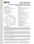
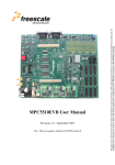
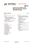
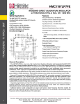
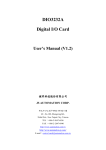
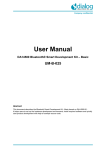
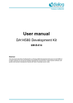
DA7210/11 USER MANUAL September 2012 User manual for the set-up and operation of the DA7210/11 evaluation board and control software DA7210/11 USER MANUAL Contents Contents 1 1 Introduction 2 2 Hardware 2 3 2.1 Power Supplies 5 2.2 Jumpers and Link Positions 6 Evaluation Board Features 3.1 4 USB Interface 13 Control Software 13 4.1 Installation 13 4.2 Set-up Files 16 4.2.1 Text File 16 4.2.2 Spreadsheet File 17 4.3 5 13 Control Panels 19 4.3.1 Front Panel 19 4.3.2 Register Map Page 0 20 4.3.3 Register Map Page 1 21 4.3.4 GP Filters Register Map 22 4.3.5 Volume Control Panel 23 RT Filters GUI 24 5.1 Software Installation 24 5.2 Control Panels 26 5.2.1 Running the Interface and USB Initialisation 26 5.3 Filter Setup Panel 28 5.4 Coefficients Tab 29 5.5 Five-band Equaliser and Voice Filter Panel 31 DA7210/11 User Manual Rev 2.8 - September 2012 © Dialog Semiconductor 2011 1 DA7210/11 USER MANUAL 1 Introduction The DA7210/11 evaluation board has been produced to allow measurement, evaluation and programming of the DA7210/11 ultra-low power audio codec evaluation board and control software. The evaluation PCB is supplied together with a DVD ROM containing documentation and driver files. The driver software uses a simple graphical user interface (GUI), allowing the DA7210/11 device to be controlled via a USB port of a PC. An additional GUI is available to control the highly configurable filter paths within the DA7210/11; including general purpose, five-band equaliser and high pass filters The board has a number of jumper links to allow configuration of the board and to provide measurement test points. Figure 1 DA7210/11 Block Diagram The accompanying software requires a PC operating Windows 2000/XP with a USB1.1 or USB2 interface. The software will run under Vista if the default installation location is changed to ‘C:\Dialog Semiconductor\’ The DA7210/11 device plus the USB Interface consume approximately 5mA in the standby state. The evaluation board and software are not guaranteed to operate in a USB hub. See the section on Power Supplies below. The control software permits configuration of the device using either pre-prepared templates or individual write and read operations to all control registers 2 Hardware There are three options available when using the DA7210/11 evaluation mainboard, Figure 2: 1. A miniboard containing the DA7210 in a CSP 49-pin package connected to evaluation board 44-179-93-02-C via jumpers J28, J30, J36 and J38, Figure 3. This board can also be used standalone or in conjunction with a customer development system. DA7210/11 User Manual Rev 2.8 - September 2012 © Dialog Semiconductor 2011 2 DA7210/11 USER MANUAL 2. A miniboard containing the DA7211-00 in a 36-pin CSP package connected to evaluation board 44-179-93-02-B via jumpers J28, J30, J36 and J38, Figure 4. This board can also be used standalone or in conjunction with a customer development system. 3. A miniboard containing the DA7211-01 in a 36-pin CSP package connected to evaluation board 44-179-93-02-E via jumpers J28, J30, J36 and J38,. This board can also be used standalone or in conjunction with a customer development system. A USB-I2C bridge is used for communication with the device, and there are number of external active components to reduce the requirement for external equipment. Figure 2 Evaluation Board 44-179-93-02-C Mainboard DA7210/11 User Manual Rev 2.8 - September 2012 © Dialog Semiconductor 2011 3 DA7210/11 USER MANUAL Figure 3 DA7210 44-179-93-04-C Miniboard Figure 4 DA7211-00 44-179-93-04-B Miniboard DA7210/11 User Manual Rev 2.8 - September 2012 © Dialog Semiconductor 2011 4 DA7210/11 USER MANUAL Figure 5 DA7211-01 44-179-93-04-E Miniboard The passive components needed for noise decoupling or charge pump operation have been placed as close as possible to the DUT pins to ensure optimum operational performance. Gerber data for the board is available on request. 2.1 Power Supplies The board is intended to be supplied by power supplies in the range +1.8V dc to +2.5Vdc (nominal). The power supplies are connected via 4mm sockets: AVDD, VDDCP, VDDDAC, VDDADC, VDDDIO, DGND and AGND. LEDs D1 to D6 will illuminate when the power supplies are correctly connected. Some devices on the board will be powered from the +5Vdc or +3.3Vdc supply produced by the USB interface module. For demonstration purposes the +5Vdc USB supply can be connected to regulator, U9, to produce +1.8Vdc capable of supplying all of the DUT the power supply pins. This configuration allows complete DUT operation using just USB and TOSLINK connections only, but maximum headphone power output will be limited when using +1.8V VDDDCP power supply. DA7210/11 User Manual Rev 2.8 - September 2012 © Dialog Semiconductor 2011 5 DA7210/11 USER MANUAL 2.2 Jumpers and Link Positions Header Link Position Function Notes J5 OUT1_L speaker connection External connection J6 OUT1_R speaker connection External connection On OUT1_L 32Ω load selected Off OUT1_L no load On OUT1_R 32Ω load selected Off OUT1_R no load J8 J9 J10 MIC_L differential connection On MICN_L single-ended input Off MICN_L differential input On OUT1N_L differential output Off OUT1N_L single-ended output On OUT1N_R differential output Off OUT1N_R single-ended output External connection J12 J18 J19 J23 MIC_R differential connection On MIC_R single-ended input Off MIC_R differential input Short link Short VDDADC current measurement point DMM link VDDADC current measurement point Short link Short VDDDAC current measurement point DMM link VDDDAC current measurement point On Headphone sense ground connected Off Headphone sense ground disconnected 1-2 HPL 16Ω load selected 2-3 HPL 32Ω load selected Short link Short AVDD current measurement point External connection J25 J26 N/A for DA7211 J27 N/A for DA7211 J29 Should be disconnected for DA7211 J31 J32 DA7210/11 User Manual Rev 2.8 - September 2012 © Dialog Semiconductor 2011 6 DA7210/11 USER MANUAL DMM link AVDD current measurement point 1-2 HPR 16Ω load selected 2-3 HPR 32Ω load selected Short link Short VDDCP current measurement point DMM link VDDCP current measurement point Short link Short XVDDD current measurement point DMM link XVDDD current measurement point Short link Short VDDDIO current measurement point DMM VDDDIO current measurement point On WCLK slave mode Off WCLK master mode On CLK slave mode Off CLK master mode 1-2 / 1-2 16-bit I2S mode 1-2 / 2-3 24-bit I2S mode 2-3 / 1-2 24-bit left justified mode 2-3 / 2-3 16-bit right justified mode 1-2 DAI input level shift enable 2-3 DAI input level shift high impedance 1-2 DAI output level shift enable 2-3 DAI output level shift high impedance On S/PDIF receiver +5V supply enabled Off S/PDIF receiver +5V supply disabled 1-2 SPDIF word clock 3-4 SPDIF bit clock 5-6 SPDIF data 7-8 SPDIF master clock J35 J37 J39 N/A for DA7211 J41 N/A for DA7211 J42 J43 J44 J47 / J44 and J47 must both be set for correct S/PDIF receiver DAI format and word length J45 J46 J48 J49 DA7210/11 User Manual Rev 2.8 - September 2012 © Dialog Semiconductor 2011 Short links only if no sources are connected to J52 7 DA7210/11 USER MANUAL J50 1-2 MCLK output 3-4 CLK output 5-6 DATOUT output 7-8 WCLK output 11-12 SO output On Control interface 2-wire ISK selected Off Control interface 2-wire ISK de-selected 1-2 DAI MCLK input 3-4 DAI CLK input 5-6 DAI DATIN input 7-8 DAI WCLK input On Control interface 2-wire SO selected Off Control interface 2-wire SO de-selected 1-2 Control interface 4-wire nCS selected 3-4 Control interface 4-wire SI de-selected 5-6 Control interface 4-wire ISK selected On XVDDD connected to VDDCP Off XVDDD disconnected from VDDCP On XVDDD connected to VDDDIO Off XVDDD disconnected from VDDDIO On VDDCP connected to AVDD Off VDDCP disconnected from AVDD On REG_+1.8V supply connected Off REG_+1.8V disconnected J51 J52 J53 J55 External connections Short only if J55 links are removed Short only if J49 links are removed Short only if J55 links removed Short only if J51 and J53 links removed J56 J57 J59 J60 Table 1 Jumpers and Link Positions DA7210/11 User Manual Rev 2.8 - September 2012 © Dialog Semiconductor 2011 8 DA7210/11 USER MANUAL The evaluation board can be set up to run solely from the +5V USB supply as the source for all board supplies. It is necessary to remove all external power supplies and to add jumpers J56, J57, J59 and J60 for this operation, which is the default configuration for the board. The digital audio interface jumpers are set to receive a TOSLINK input and should be removed to accept other external clocks at J52. Figure 9 shows the extra links required to enable the onboard supplies. Figure 6 DA7210 Default Link locations DA7210/11 User Manual Rev 2.8 - September 2012 © Dialog Semiconductor 2011 9 DA7210/11 USER MANUAL Figure 7 DA7211-00 Default Link Locations DA7210/11 User Manual Rev 2.8 - September 2012 © Dialog Semiconductor 2011 10 DA7210/11 USER MANUAL Figure 8 DA7211-01 Default Link Locations DA7210/11 User Manual Rev 2.8 - September 2012 © Dialog Semiconductor 2011 11 DA7210/11 USER MANUAL Figure 9 shows the locations of the jumper links when using the DA7210 with external power supplies to AVDD J66, VDDCP J17, XVDDD J62 and VDDDIO J64. The digital audio interface jumpers are set to receive a TOSLINK input and should be removed to accept other external I2S clocks at J52. Figure 9 External Power Supply Jumper Configuration DA7210/11 User Manual Rev 2.8 - September 2012 © Dialog Semiconductor 2011 12 DA7210/11 USER MANUAL Evaluation Board Features 3 3.1 USB Interface The USB Interface is used here for the following purposes: As a source of I2C and SPI control signals. To provide a discrete signal to the power down pin PD (DA7210 only). To provide level shifting voltages. To allow standalone operation of the evaluation board using the +5Vdc USB power supply only. The USB control signal device is powered by the USB bus cable via a fixed +3.3V dc regulator. The USB interface control signals can be isolated from rest of the evaluation board by removing J51, J53 and J55 described in Table 1. Removing these jumpers will allow external signal access to the DA7210 control interface. The USB interface can also be used to supply the power supplies to the DUT on the evaluation board. The USB Interface implements multi-mastering on its I2C interface, permitting concurrent operation with any other multi-mastering controller. This allows the software to control a DA7210/11 device which is already part of the users system, and under control of the system processor. 4 Control Software 4.1 Installation Insert the DVD-ROM containing the software into the controlling PC. If the installation does not start automatically, run the program ‘setup.exe’ from the DVD-ROM containing the software. An automated script will install the program to your PC. By default, the directory ‘C:\ProgramFiles\Dialog Semiconductor\Audio\DA7210 Rev x.x’ will be used. As Windows Vista imposes limitiations on the ‘C:\Program Files’ directory, change this default to ‘C:\Dialog Semiconductor\Audio\DA7210 Rev x.x’ when prompted. Plug in the USB cable, and Windows will detect the USB device. It will prompt for the drivers, which should be automatically located on the root directory of the DVD-ROM. The setup file is '’dlgezusb.inf’ and the following description explains how to install the driver. Select No, not this time and press Next > DA7210/11 User Manual Rev 2.8 - September 2012 © Dialog Semiconductor 2011 13 DA7210/11 USER MANUAL Select Install from a list or specific location (Advanced) and press Next > Select Browse and locate the folder C:\Program Files\Dialog Semiconductor\Audio\DA7210_11 Rev x.x DA7210/11 User Manual Rev 2.8 - September 2012 © Dialog Semiconductor 2011 14 DA7210/11 USER MANUAL Select dlgezusb.inf and press Next > Press Continue Anyway Select Browse and locate C:\Program Files\Dialog Semiconductor\Audio\DA7210_11 Rev x.x then press OK DA7210/11 User Manual Rev 2.8 - September 2012 © Dialog Semiconductor 2011 15 DA7210/11 USER MANUAL Select Finish If you are using Windows XP, you may get a message saying that a USB2 device is attached to a USB1.1 port. This can safely be ignored. To uninstall the software please use the Windows ‘Add/Remove Programs’ function that can be found under ‘Start->Settings->Control Panel’. 4.2 Set-up Files 4.2.1 Text File The DUT registers can written to by submitting a text file containing the register values; Figure 10 shows an example file. Only the data in the first three columns is required: register, data, R/W; other comments, such as those shown in the example, will be ignored. Lines of text that do not follow register write entries should be preceded by // in order that the line is ignored when reading the text file. The text file can be created by saving the first three columns of the template spreadsheet file above as a text file or can be created from scratch; it is only necessary for the text file to contain the registers required for set up all others can be omitted. To add a delay in the file the register value is entered as Delay followed by the delay time require in milliseconds. The example in Figure 10 shows a 100ms delay added as the third entry. DA7210/11 User Manual Rev 2.8 - September 2012 © Dialog Semiconductor 2011 16 DA7210/11 USER MANUAL Figure 10 Text Set-up File A selection of text files can be found on the DVD containing the register control software setup files. 4.2.2 Spreadsheet File The register settings can be prepared using a spreadsheet file template provided, Figure 11, and saved as a tab delimited text file like Figure 10. The only bits that can be altered on the spreadsheet are the individual register bits in columns G to N and the R/W bit in column O. If any of these bits are set to 1 the bit will be highlighted in green on the register map. If the bit default setting is 1 and the bit value is changed to 0 then the register map bit will be highlighted in grey. This highlighting allows easy visual reference to the register changes from the default settings. DA7210/11 User Manual Rev 2.8 - September 2012 © Dialog Semiconductor 2011 17 DA7210/11 USER MANUAL Figure 11 Spreadsheet Set-up File DA7210/11 User Manual Rev 2.8 - September 2012 © Dialog Semiconductor 2011 18 DA7210/11 USER MANUAL 4.3 Control Panels Run the DA7210/11 program by clicking the shortcut on the appropriate item in the Start menu. The best setting for the PC display size is 1024x768 pixels or above. Font size on the PC display should be Normal (95dpi). It is important to note that a display size other than the recommended setting may affect the way in which the panels appear. 4.3.1 Front Panel The front panel allows selection of a number of methods for programming the registers of the DUT. Submit a text file template, which allows register sequencing and time delays to be added. Select register map page 0 for individual register read/write access. Select register map page 1 for individual register write access. Select general purpose filters register map for individual register write access. Open a panel to access the volume control registers for real time volume control. Direct read/write access to a single register. Figure 12 Front Panel Any file path required can be opened using the ‘…’ button to the right of the corresponding text box, but it must then be submitted or saved using the submit button to the left of the corresponding text box. DA7210/11 User Manual Rev 2.8 - September 2012 © Dialog Semiconductor 2011 19 DA7210/11 USER MANUAL It is possible to save the present register settings by selecting a spreadsheet file by locating the filename path using the ‘Save present register setting to spreadsheet’ box. This function will not read back the device registers, but will only output the values shown on Page 0 and Page 1 of the GUI. The front panel also contains a reset button, a device power down button and 2-wire/4-wire control selection. 4.3.2 Register Map Page 0 The page 0 register map panel allows read/write access to single bits or to the hex value of a single register; both can be submitted individually. Figure 13 Register Map Page 0 To select readback of an individual register click on the R/W bit of the required register and select R. To read the value press the submit button of the same row. DA7210/11 User Manual Rev 2.8 - September 2012 © Dialog Semiconductor 2011 20 DA7210/11 USER MANUAL Figure 14 Selecting Individual Register Readback A pop up window will then appear displaying the readback value of the register, Figure 15. Figure 15 Readback Pop-up Window To select readback of all Page 0 register simultaneously press the read all button at the base of the R/W column. This will write the register readback values to a spreadheet file at the following location: C:\Program Files\Dialog Semiconductor\Audio\DA7210_11 Rev x.x \Page0_Readback_Values.xls Figure 16 Readback All Registers 4.3.3 Register Map Page 1 The page 1 register map panel allows access to single bits or to the hex value of a single register; both can be submitted individually. Readback from Page 1 registers is limited, but individual register readback can be selected in the same way as Page 1 where available. DA7210/11 User Manual Rev 2.8 - September 2012 © Dialog Semiconductor 2011 21 DA7210/11 USER MANUAL Figure 17 Register Map Page 1 4.3.4 GP Filters Register Map The general purpose filters register map panel allows access to the hex value of a single register; all registers are submitted after changes. All registers may also be reset using the Reset Filters button. Figure 18 Filter Coefficients Set-up Panel An alternative ’RT Filters’ GUI is available that allows easy submission of any of the DAC or ADC filters paths present within the DA7210/11. This is contained on the installation DVD within the distribution kit. DA7210/11 User Manual Rev 2.8 - September 2012 © Dialog Semiconductor 2011 22 DA7210/11 USER MANUAL 4.3.5 Volume Control Panel The Volume Control panel allows real time changes to any of the analogue input or output PGAs within the DUT. Muting is also possible where this function exists. Gain controls are available to the following PGAs: AUX_L and AUX_R MIC_L and MIC_R A2 PGA Left and Right Input PGAs OUT1_L and OUT1_R HPL and HPR OUT2 It is possible to change the headphone and OUT1 gain control registers as stereo pairs by simultaneously selecting the HPL follow HPR and OUT1L follow OUT1R buttons. Figure 19 Volume Control Panel DA7210/11 User Manual Rev 2.8 - September 2012 © Dialog Semiconductor 2011 23 DA7210/11 USER MANUAL 5 RT Filters GUI The RT filters GUI allows easy control of all the filter options within the DA7210/11 device through USB control. This includes general purpose filters, five-band equalisers and voice filters for ADC and DAC. The Filter Setup page makes it possible to design the required filter response for all of the general purpose filter bi-quad IIR paths available in the DA7210/11. 5.1 Software Installation The set-up file for the RT Filters control software can be found on the accompanying DVD in the folder DA7210 RT Filters Rev x.x Double click setup.exe file and the install will begin. Do not change the installation directory or necessary license files will not be accessible. DA7210/11 User Manual Rev 2.8 - September 2012 © Dialog Semiconductor 2011 24 DA7210/11 USER MANUAL Select I accept the License Agreement and press Next>> Press Next>> Allow the application to install. If Labview run-time files have not been installed on the target computer previously, the installation may take a few minutes. DA7210/11 User Manual Rev 2.8 - September 2012 © Dialog Semiconductor 2011 25 DA7210/11 USER MANUAL When installation is complete press Finish 5.2 Control Panels 5.2.1 Running the Interface and USB Initialisation The RT Filters Rev x.x GUI can be used in conjunction with the DA7210_11 Register Control Software Rev x.x to set up the DA7210/11 device registers. In order to allow both interfaces to access the DA7210/11 simultaneously it is necessary to initialise the RT Filters GUI first before opening the DA7210_11 Register Control Software. The flowchart in Figure 20 details the start-up procedure when using the DA7210 Register Control GUI and RT Filter GUI in conjunction with each other. On starting-up the RT Filters application the interface will be running. Once the coefficients are calculated the interface will stop and the registers writes will be submitted to the DA7210/11. To start the interface running again, press the white arrow situated below the Operate drop down menu on the top row; this will turn to black and the interface is running again ready for new selections. DA7210/11 User Manual Rev 2.8 - September 2012 © Dialog Semiconductor 2011 26 DA7210/11 USER MANUAL Open ‘DA7210_11 RT Filters’ GUI Open ‘DA7210_11 Register Control’ GUI Select ADC 5-Band Equaliser Settings Load Register Setting into Register Setting GUI Select ADC Voice Filter / ADC HPF Settings 5-Band Equaliser Selection What Filtering is Required? Voice and HP Filters Selection Select DAC 5-Band Equaliser Settings General Purpose Filters Select DAC Voice Filter / DAC HPF Settings Select Signal Paths for DAC, ADC, DAI and/or GP Filters Press ‘SUBMIT’ Button Select GP Filter Specifications or Enter Text File Filter Response Yes Are Any GP Filter Paths Selected? No Enter I2S Sample Rate Press ‘SUBMIT PATHS’ Button Press ‘CREATE COEFFICIENTS’ Button Figure 20 RT Filter Setup Flowchart DA7210/11 User Manual Rev 2.8 - September 2012 © Dialog Semiconductor 2011 27 DA7210/11 USER MANUAL 5.3 Filter Setup Panel The Filter Setup panel makes it possible to design desired filter responses through any of the general purpose filter banks, using the filter specification selections. Figure 21 Filter Setup Panel The Filter Setup panel controls the following realtime filter path selections: DACL and DACR input sources Enabling GP1AB, GP1CD, GP2AB and/or GP2CD GP1AB, GP1CD, GP2AB and GP2CD input sources Mixing of GP1AB and GP1CD, GP1CD and GP1CD or GP2AB and GP2CD For each of the filter specifications blocks the following settings are available: Topology – Butterworth, Chebyshev, Inverse Chebyshev, Elliptic, Bessel Type – lowpass, highpass, bandpass, bandstop Order – order 2 should be used lowpass and highpass filters and order 1 for bandpass and bandstop filters only Lower Fc – lower frequency cut-off Upper Fc – upper frequency cut-off PB Ripple – passband ripple level SB attenuation – sideband attenuation level DA7210/11 User Manual Rev 2.8 - September 2012 © Dialog Semiconductor 2011 28 DA7210/11 USER MANUAL Pressing the Submit Paths button allows real-time selection of the filter path set-up while the interface is running. The resultant coefficients from the selected filter responses can be calculated and submitted to the DA7210/11 by pressing the Calculate Coefficients and Register Settings button. The coefficients sent to the DA7210/11 are displayed on the Coefficients panel. Important: Be aware that if any of the general purpose filter paths are selected and no coefficients have been entered, then the DA7210/11 will be unable to pass the signal to the selected output. 5.4 Coefficients Tab The Generate Coefficients panel displays the forward and reverse coefficients for all of the general purpose filters and lists the register writes submitted to the DA7210/11. Here it is also necessary to enter the sample rate of the digital audio interface, so that the correct coefficient values are created; failure to do so will result either in zero entries or incorrect coefficient values. The Calculate Coefficients and Register Settings button will perform the same action as the button of the same name on the Filter Setup panel. The forward and reverse coefficients can be saved to file by selecting Output Coefficients button and by selecting a valid output file path. The spreadsheet file must already exist for the register values to be output. Figure 22 Coefficients Panel DA7210/11 User Manual Rev 2.8 - September 2012 © Dialog Semiconductor 2011 29 DA7210/11 USER MANUAL It is also possible to input coefficients to the device from spreadsheet by selecting Input Coefficients button and by selecting a valid input file path. Three forward and two reverse coefficients are required, an example is found in Figure 23. Figure 23 Input Coefficient Spreadsheet Example Another facility on the Generate Coefficients panel allows the register values to be output to spreadsheet by selecting the Output Coefficient Registers button and by selecting a valid output file path. The spreadsheet file must already exist for the register values to be output. The I2C device address and access speed can also be entered here. DA7210/11 User Manual Rev 2.8 - September 2012 © Dialog Semiconductor 2011 30 DA7210/11 USER MANUAL 5.5 Five-band Equaliser and Voice Filter Panel The EQ & Voice panel contains the controls for selection of the ADC and DAC five-band equalisers and for the voice filters. These registers can be submitted real-time while the interface is running by pressing the Submit button. Figure 24 Five-band Equaliser and Voice Filter Panel DA7210/11 User Manual Rev 2.8 - September 2012 © Dialog Semiconductor 2011 31 DA7210/11 USER MANUAL Dialog Semiconductor worldwide offices Germany (Headquarters) Japan Korea Taiwan USA United Kingdom Tel: (+49) 7021 805-0 Tel: (+81) 3 3769 8123 Tel: (+82) 2 6007 2303 Tel: (+886) 37 598 166 Tel: (+1) 408 727 3200 Tel: (+44) 1793 757700 Fax: (+49) 7021 805-100 Fax: (+81) 3 3769 8124 Fax: (+82) 2 6007 2001 Fax: (+886) 37 595 026 Fax: (+1) 408 727 3205 Fax: (+44) 1793 758000 Netherlands China Tel: (+49) 7021 805-0 Tel: (+852) 2607 4271 Fax: (+49) 7021 805-100 Fax: (+852) 2607 4169 Email: Web: [email protected] www.dialog-semiconductor.com This publication is issued to provide outline information only, which (unless agreed by Dialog Semiconductor in writing) may not be used, applied or reproduced for any purpose or form part of any order or contract or be regarded as a representation relating to products or services concerned. Dialog Semiconductor reserves the right to alter without notice the specification, design, price or conditions of supply of the product. Customer takes note that Dialog Semiconductor’s products are not designed for use in devices or systems intended for supporting or monitoring life nor for surgical implants into the body. Customer shall notify the company of any such intended use so that Dialog Semiconductor may determine suitability. Customer agrees to indemnify Dialog Semiconductor for all damages that may be incurred due to use without the company’s prior written permission of products in such applications. DA7210/11 User Manual Rev 2.8 - September 2012 © Dialog Semiconductor 2011 32