1
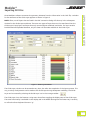
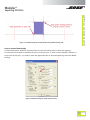
Modeler®
Importing DXF Files
APPLICATION NOTE
Introduction
Starting with version 6.6, Bose® Modeler® sound system software contains new features designed to
facilitate the import of two and three-dimensional drawing files. These features allow you to leverage
work performed outside the Modeler environment within popular 2D and 3D drawing environments. Two
new import file types are now supported:
•
Modeler Text Format files (.MTF)
created by the Bose Modeler Software Plugin for Google® SketchUp®.
•
Drawing exchange format files (.DXF)
created by Autodesk® AutoCAD® and other compatible drafting applications.
This application note describes the import of .DXF files and how to start work in Modeler based on the
imported drawings. Modeler offers the following .DXF import features:
•
Import of 2D and 3D .DXF files. A 2D drawing is imported into a special Guide Layer that facilitates
the creation of a three-dimensional room model. A 3D drawing is imported as a three-dimensional
geometric model that can be used right away as a starting point for design work within Modeler
software.
•
Preservation of layer structure. The import tool preserves name and color of the layers as defined
in the .DXF file. Layers for 2D import are selectable from a list of all available layers in the .DXF
file and are adjustable in color and elevation. When a 3D file is imported, apart from the choice of
layers and the adjustment of colors, materials as well as surface types can be assigned to each layer.
•
Both types of .DXF files allow the adjustment of their scale and with 2D files, offset and orientation
of the drawing may also be defined by the user.
•
The snapping functionality of Modeler software’s various drawing tools is extended to the 2D
drawing in the Guide Layer which, together with the various extrusion tools, allows for a very
effective creation of a three-dimensional room model.
The information in this application note is organized into three primary sections:
Section 1: Importing a .DXF drawing into Modeler software
Section 2: Start working with a 2D drawing
Section 3: Start working with a 3D model
Associated Reading:
Modeler 6.6 Software User Manual
Modeler Application Notes
Preparing AutoCAD Files For Bose Modeler Software Import
Bose Professional Systems Division
1
OF 19
pro.Bose.com
Modeler®
Importing DXF Files
APPLICATION NOTE
Section 1 – Importing a .DXF File
Import of AutoCAD® 2D .DXF files
You can either chose to open a single 2D .DXF drawing or to add it to the currently opened project. You
cannot import a 2D .DXF drawing into an already existing model. In order to import a 2D .DXF file,
1. Select File - Import Model - AutoCAD DXF File.
Alternatively, you may use the keyboard shortcut Ctrl-I.
2. Browse the file system to locate the 2D AutoCAD file of interest, select it, then click OPEN.
3. The following DXF conversion dialog will determine how the DXF file will be imported into
Modeler® software as a Guide Layer within the room model.
NOTE: With very complex .DXF files, it may take a while until the DXF conversion window is displayed.
Note the status bar.
Figure 1 – 2D .DXF file conversion
The DXF conversion dialog shows all available layers in a spreadsheet that can be sorted by clicking on the
header of each column. All layers are selected for import by default but can also be checked individually.
Selecting the checkbox in the Layer header toggles all layers on/off. For each layer, its elevation in the
Guide Layer and its color can be adjusted. Select OK to accept the parameters and to begin the import
process.
2
OF 19
pro.Bose.com
Modeler®
Importing DXF Files
APPLICATION NOTE
Once Modeler® software constructs the geometry elements from the information in the .DXF file, a window
for the attributes of the Guide Layer appears as shown in Figure 2.
NOTE: Often, not all layers that are listed in the DXF conversion dialog will show up in the subsequent
window for the Guide Layer attributes. There are two types of layers that won’t be transferred into the
Guide Layer: Empty layers and layers that only contain objects combined into blocks. If a layer contains
both blocked and exploded elements, only the latter will be made available in the Guide Layer.
Figure 2 - Guide Layer Attributes
The Guide Layer window can be accessed at any time, also after the completion of the import process. This
way, a variety of adjustments can be made to the Guide Layer during subsequent modelling. The Guide
Layer can be accessed by selecting the Guide Layer icon in the Arrange toolbar: .
The Guide Layer icon also features a wing-menu that allows toggling the display state of the Guide Layer.
The same functionality is available via the Display tab in the Model Settings but the fastest way is certainly
to utilize the direct keyboard shortcut “g”.
3
OF 19
pro.Bose.com
Modeler®
Importing DXF Files
APPLICATION NOTE
The Guide Layer window is organized in five main sections. The bottom of the window shows a
spreadsheet with all imported layers that contained valid geometry data. Make sure that the colors set
for these layers are distinguishable from the background color you chose for the Model window. As in
the conversion dialog, the list can be sorted, layers can be selected for display and the elevation of the
displayed layer can also be adjusted. The upper section of the Guide Layer window contains four important
options to adjust the appearance of the Guide Layer content within the Model window:
1. Scale. This section defines the Units that will be used for the imported DXF data. This selection is
important since a .DXF file does not contain any information about the scale that was used during
the creation of the drawing. You can select between standard Metric units (meter, centimeter,
millimeter), English units (feet, inches) or you can chose a custom scaling (“Other”). If the latter is
used, a scale factor can be defined in the Scale text box.
2. Offset. This section determines where Modeler® software locates the Guide Layer content within
the Model Window. If the pull-down menu for “Centering” is set to “Automatic”, the DXF data
will be centered in the model based on the extent of the data in the two dimensions available.
If the menu is set to “Manual”, offset coordinates can be entered in the two respective fields. If
the values are set to Zero, the origin of the “Global Coordinate System” within the original .DXF
drawing will be placed at the Modeler® software coordinate system origin. Any other number for
offset will re-locate the Guide Layer content with regards to this reference. Further information on
how to best center an imported .DXF drawing is provided at the end of this chapter.
3. Rotate. This section allows the adjustment of the basic orientation of the imported layer(s) as well
as any additional rotation around the Modeler software coordinate system origin. While the latter
may be less frequently applied, note that you can utilize the “Orientation” setting to import a
cross-sectional drawing of the room and start modeling from there, e.g., by applying the Extrude
Surface tool. Note that once you change the orientation, the axis available for “Offset” will change
accordingly. The “Rotate” section also allows you to invert (i.e., mirror) the Guide Layer content at
one of the two available main axis.
4. Drawing. This section allows you to enter the width of the lines as drawn in the Guide Layer. We
recommend keeping this value small in order to avoid cluttering of the display. Also available is
an option that allows you to display any vertices within the Guide Layer content. This function
is important with regards to Modeler software’s ability to have its drawing tools snap to vertices
within the Guide Layer. With vertices shown, the user is able to distinguish a valid snap location
from a simple crossing of two lines.
Import of AutoCAD® 3D .DXF files
You can either chose to open a single 3D .DXF model or to add it to the currently opened project. In order
to import a 3D .DXF file.
1. Select File - Import Model - AutoCAD DXF File. (Keyboard shortcut Ctrl-I.)
2. Browse the file system to locate the 3D AutoCAD file of interest, select it, then click OPEN.
3. The following DXF conversion dialog will determine how the DXF file will be imported into
Modeler software as a room model.
4
OF 19
pro.Bose.com
Modeler®
Importing DXF Files
APPLICATION NOTE
Figure 3 – DXF conversion dialog
As with 2D import, the 3D DXF conversion dialog shows all available layers in a spreadsheet that can be
sorted by clicking on the header of each column. Again, layers can be checked individually for import.
Selecting the checkbox in the Layer header toggles all layers on/off. For each layer, its material, surface type
and its color can be adjusted. Assign materials to each layer by dragging the desired material from the set
of material databases on the left side of the window onto the respective cell-entry within the spreadsheet.
You can now also assign Modeler® software specific surface types and color to each layer. Select OK to
accept the parameters and to begin the import process. Once Modeler software constructs the geometry
elements from the information in the .DXF file, a window for the scale of the DXF drawing will appear as
shown in Figure 4.
Figure 4 – 3D DXF Scale
As with the Guide Layer window, the section Scale defines the units and scale that will be used for the
imported DXF data. Again, select between “Metric” or “English” units or custom scaling by choosing the
“Other” option and entering the scale factor in the associated text box. Model Dimensions displays the
overall extents of the imported .DXF data in the selected units and should give you a good indication
about whether the chosen scale factor is roughly correct.
5
OF 19
pro.Bose.com
Modeler®
Importing DXF Files
APPLICATION NOTE
How to center a 2D Guide Layer or a 3D model
As described for the Guide Layer window, it is in general advisable to adjust the offset of the imported
drawing. This section describes an easy-to-use method to exactly center the room model and, if applicable,
the two-dimensional Guide Layer around a user-defined location within the room model.
Starting with version 6.6, Bose® Modeler® software offers an option to center model and Guide Layer
around the location of any of the following room model items:
• a vertex of any surface in the model,
• a loudspeaker or
• a listener.
For the purpose described in this section we recommend to utilize the first option of centering the model
and Guide Layer around the vertex of a surface within the model. The following example attempts to
explain the recommended method for application with a 2D Guide Layer. For simplicity, the .DXF drawing
consists of just the playing field of a soccer arena but of course, the method also applies to much more
complex models.
For this example, we will adjust the offset of the model and the Guide Layer such that the midpoint of the
soccer field will coincide with the Modeler software (0,0,0) coordinate system origin. But first, let’s take a
look at how the drawing will be imported using “Automatic” offset:
Figure 5 – Soccer field with “Automatic” Guide Layer offset
6
OF 19
pro.Bose.com
Modeler®
Importing DXF Files
APPLICATION NOTE
With “Automatic” centering, Modeler® software places the Guide Layer such that the maximum extent of
the drawing in both dimensions (here: x and y) is centered around the Modeler software origin. In this case,
the model does not only contain the soccer field (the geometry of interest) but also two other elements
that skew the offset of the Guide Layer. This way, the playing field is offset to negative x and also towards
positive y.
The next figure shows how the model is centered when “Manual” offset is chosen and both the x and
y offsets are set to zero. This way, the Modeler software origin coincides with the origin of the Global
Coordinate System within the original .DXF drawing. Using this option, the midpoint of the field is offset
even further from the Modeler software origin.
Figure 6 – Soccer field with “manual” centering and zero offset for x and y
7
OF 19
pro.Bose.com
Modeler®
Importing DXF Files
APPLICATION NOTE
As you may note, the .DXF drawing contains a little triangle depicted in blue. This triangle was added
to the .DXF drawing in order to facilitate the method of centering described below. Let’s zoom into the
middle to the soccer field:
Figure 7 – Midpoint of soccer field with guide object for the helper surface
Note that the triangle was drawn such that the tip coincides with the midpoint of the field. We now want
to draw a helper surface in Modeler® software, which utilizes the ability to snap to vertices of the Guide
Layer, and coincides exactly with the blue triangle. Let’s zoom in again on the tip of the triangle, this time
with the Guide Layer vertices displayed:
Figure 8 – Midpoint of soccer field with tip of guide object (vertices turned on)
Note the many vertices that make up the small circle at the midpoint. It would be very hard to exactly
place a vertex of a helper surface in this region since so many Guide Layer vertices are valid candidates for
snapping.
8
OF 19
pro.Bose.com
Modeler®
Importing DXF Files
APPLICATION NOTE
Thus, we will temporarily turn off all layers except the one that contains the blue triangle:
Figure 9 – Midpoint of soccer field with field layer turned off
We can now use the Draw Polygonal Surface tool to create a helper surface on top of the triangle. The
following figure shows the model including the new helper plane. For better clarity, we have floated the
Detail Window and chose the Properties Tab showing the properties of the newly created helper surface.
Figure 10 – Soccer field with helper plane and vertex properties
9
OF 19
pro.Bose.com
Modeler®
Importing DXF Files
APPLICATION NOTE
Note that we have selected the vertex at the midpoint of the field (#0) and also its arbitrary offset from
zero. Now, right-click into the row describing the coordinates of the desired vertex and chose “Center
Vertex” as depicted in the figure below:
Figure 11 – Center Vertex function
Both the model surface(s) and the Guide Layer content will now be moved such that the chosen vertex
coincides precisely with the Modeler® software coordinate system origin as seen in the figure below:
Figure 12 – Centered Guide Layer and model. Note precise midpoint placement.
10 OF 19
pro.Bose.com
Modeler®
Importing DXF Files
With 3D .DXF models, the concept of centering around a surface’s vertex is identical to the method above.
Nonetheless, all issues related to snapping to the Guide Layer are not applicable, simply because there is
no Guide Layer in use. Thus, all subsequent centering is applied to the model only. You may either center
around any vertex of any surface that was imported with the 3D model or you may chose to insert a helper
surface in case you don’t have a vertex available in the desired location. You may also place a listener
or loudspeaker at the desired location and apply the “Center Listener” or “Center Loudspeaker”
algorithm, analogous to “Center Vertex”. Note that the centering function works in all three major room
dimensions, so in case you want to avoid that the z-coordinates of the model are changed, make sure that
your reference vertex/listener/loudspeaker for centering has an elevation of zero.
Section 2 – Start working with a 2D drawing
APPLICATION NOTE
NOTE: The “Center Vertex” functionality is only available in the Properties Tab within the Detail Window,
i.e., not via the Properties in the right-click-menu.
General modeling strategies
Before you import a .DXF drawing into Modeler® software and start working with the creation of a 3D
simulation model, you should think about the best way to build your geometry. The “best” way in this
sense means: Minimize modeling time by utilizing as many “semi-automatic” drawing tools as possible. The
tools for the extrusion of surfaces are very powerful when used in conjunction with a Guide Layer. The two
following examples illustrate this:
In a first example, imagine you have to create a model for a room that features are complex floor shape,
with lots of corners, recessed wall elements, dedicated seating areas, columns that need to be cut out of
the floor, etc. but at the same time, with a relatively simple, i.e., uniform, ceiling structure. In such a case,
the recommended approach is to import a floor plan into the Guide Layer and using the Draw Polygonal
Surface tool to create a polygon that follows the outline of the room. Then, use the Extrude Walls tool to
create side walls and a flat ceiling of continuous height. Or use the Extrude Surface tool to clip the side wall
extrusion at more complicated ceiling shapes, such as a barrel vault.
In a second example, should you have to model a room with a simple-shaped floor plan but a
complicated, auditorium-like ceiling, it may be more efficient to import a cross-sectional drawing of
the room, rotate the Guide Layer to the correct orientation and center it appropriately, e.g., such that the
floor level is at zero height. Now, use the Draw Polygonal Surface tool and create a polygon that follows
the outline of the room in this sectional view and which will define the footprint for an extrusion. Create
two bounding surfaces at the desired location of the two side walls. Now, use the Extrude Surface tool and
extrude the footprint surface towards the two boundaries with the termination setting “Closed”.
11 OF 19
pro.Bose.com
Modeler®
Importing DXF Files
With a detailed architectural drawing available in the Guide Layer, it is very tempting to follow every small
edge available, especially since Modeler® software allows the various drawing tools to snap onto available
vertices in the Guide Layer.
In general, it is not recommend to follow this approach for two different reasons. One is that too much
detail in the geometry of a model for acoustic predictions slows down calculations. (More information
about this aspect can be found in section 3). The other, equally important, aspect is that - in general building and especially modifying room models becomes much trickier when the vertices of surfaces leave
the smallest available Room Snap Grid in Modeler software (0.1 meter). While various snapping algorithms
within Modeler software help overcoming the associated problems, it is typically more time-consuming to
build models whose major surfaces do not coincide with the room snap grid. Below, we try to outline one
possible strategy to work with an imported 2D Guide Layer that has proven to work quite conveniently.
APPLICATION NOTE
How much detail ?
For this section, we assume that you are familiar with the content of section 1 and have a suitable .DXF
drawing imported and oriented in the model.
The main decision you need to make while using a Guide Layer is: When should I snap to a Guide Layer
vertex and when should I “draw on top of” the Guide Layer by utilizing the Room Snap Grid only. The
following picture shows a screenshot of part of the ground floor of an indoor swimming pool.
Figure 13 –Imported Guide Layer of a swimming pool.
12 OF 19
pro.Bose.com
Modeler®
Importing DXF Files
APPLICATION NOTE
In this example we can depict some good candidates for snapping to vertices. Especially the angled
boundaries of the pools would be hard to do without utilizing the snapping functions. The next screenshot
shows an enlarged detail of the situation:
Figure 14 –Model surface created on top of one pool.
Note the blue indicators of available vertices in the Guide Layer. Many vertices describe the various
curvatures with a detail that is not required for our purpose. Thus, the contour of the pool has been
followed with a reduced set of vertices.
In a second example (from the same project), we look at a part of the Guide Layer drawing where
snapping to its vertices would be less convenient when further proceeding with the model. There are two
elements in this part of the model we’d like to use for guidance: the location of the upper side wall and
the footprints of rectangular columns that support this side wall. Of course it is possible to again use the
snapping functionality and place model elements precisely over the Guide Layer elements but a detailed
inspection of the side wall of this example would reveal that it is not precisely parallel to the x-axis, but
offset by some millimeters at one edge.
Such a slightly angled surface is hard to work with, it gets difficult to join adjacent surfaces or to add
vertices at exact locations. We will thus create a wall surface that only comes close to the actual drawing
reference but that will rest on the closest available room snap grid. Typically, the resulting error is in the
range of a couple of centimeters and thus negligible. The following screenshot shows the respective part of
this model.
13 OF 19
pro.Bose.com
Modeler®
Importing DXF Files
APPLICATION NOTE
Figure 15 –Imported Guide Layer with side walls and column locations.
The next issue with this particular Guide Layer is the fact that one edge of the square column footprints
does not coincide with edge of the wall. This can be seen if one zooms into the boundary:
Figure 16 –Misalignment of side wall and edge of column.
There’s just no sense in trying to be accurate and to model the column where it’s precisely located in the
Guide Layer - it makes much more sense to have it align with the side wall. The following figure shows the
same part of the model with a column footprint and a side wall element added by utilizing a 0.1 m Room
Snap Grid. Note that the column edge is now precisely aligned to the side wall. Note also the very small
misalignment of a few centimeters at the other side of the column.
14 OF 19
pro.Bose.com
Modeler®
Importing DXF Files
APPLICATION NOTE
Figure 17 –Column footprint and wall drawn using the Room Snap Grid.
Snap to vertex functionality
As mentioned before, Modeler® software allows its various drawing tools to utilize the snapping
functionality with regards to available vertices in the Guide Layer. In order to allow Modeler software to
snap to the Guide Layer, you need to check the appropriate box in the Drawing/Saving tab of the Model
Settings.
Figure 18 –Model settings to enable snap to vertex .
15 OF 19
pro.Bose.com
Modeler®
Importing DXF Files
1. If you want to want to snap to model surfaces alone, you either need to temporarily turn off
the complete Guide Layer (Keybd-shortcut ”g”) or you turn off only the layers that contain the
elements that get into the way (see the centering example in section 1).
2. If you want to snap to the Guide Layer alone, you need to disable the display of any model
surfaces that get into the way of Guide Layer vertices by turning off the respective Surface Types in
the Display Tab of the Model Settings. This may also require to temporarily change the assignment
of Surface Type to some surfaces.
The display of vertices can be toggled with a checkbox in the Drawing section of the Guide Layer window
as displayed in the figure below.
APPLICATION NOTE
Since vertices in the Guide Layer may be located in very close proximity to each other, it is recommend to
set the sensitivity for snapping to a small value and zoom into the drawing during surface creation in order
to ensure sufficient visibility of details. The Snap To Vertex setting does not distinguish between vertices in
the Guide Layer or in the actual model - once activated, it applies to both. This may be disadvantageous in
two situations:
Figure 19 – Toggle vertex display in Guide Layer Attributes.
Note: Modeler® software snaps to the available vertices of an element in the Guide Layer but not to
intersections of elements. Thus, displaying the vertices of the Guide Layer is recommended.
Surface visibility
Another interesting feature of the Guide Layer is the ability to choose the elevation of the various layers.
This way, layers that describe floors and walls can be placed at zero height and layers that describe lighting
elements, cable trusses, or ceiling support structures, can be placed at the actual mounting height in order
to simplify collision detection when placing loudspeakers.
Layers are displayed in the Model view at an elevation as specified in the Guide Layer window. Depending
on their z-coordinates, surfaces created in Modeler software may appear differently if their vertices result
in being either above, below or at the same height as the respective layer elevation. The following pictures
try to illustrate this situation:
16 OF 19
pro.Bose.com
Modeler®
Importing DXF Files
APPLICATION NOTE
Figure 20 – Guide Layer only (left) and with surface above (right). Note regular (black) surface edges.
Figure 21 – Guide Layer at same height as surface (left) and above surface (right). Note color change of surface edges
and details to vertex indicators.
This artifact also appears during the creation phase of a new surface whose egdes lie exactly above lines
from the Guide Layer, which is normal when you utilize snapping to vertices of the Guide Layer: These
collinear edges disappear during surface creation as can be seen in the example below.
Figure 22 – “Disappearing” edges of newly created surface with Guide Layer at elevation ≥ Zero.
17 OF 19
pro.Bose.com
Modeler®
Importing DXF Files
Depending on the original purpose of the 3D .DXF model you received, it may not be suitable for acoustical
modeling right away. In general, a good acoustical model requires much less detail than an architectural
model. Too much detail does not only slow down calculations, it may also cause inaccurate results. It is
therefore good practice to simplify a 3D model should it contain too much detail. As a general rule, don’t
model surfaces with an extent of less then 0.5 to 1.0m in any dimension. Among others, some common
recommendations are:
•
Don’t build stairs by modeling all their individual steps. Instead, model a continuous surface with
scattering reflection characteristics.
•
Don’t model window or door frames that are just some centimeters deep. Remove those elements
and replace them by doors and windows from the respective Modeler® software toolbar. These
elements are much more efficient with regards to acoustical modeling.
•
Remove any decorative elements like chairs or other furniture. Instead, try to understand their
acoustical behavior and assign corresponding characteristics to the underlying surfaces. Do not
remove elements that do have an important acoustic property, e.g., a shelf that obstructs parts of
the room from direct sound arrivals.
•
Remove support structures (e.g., steel elements in the ceiling) as long as they are small (sound will
typically diffract around them), unless they are required, for collision detection.
APPLICATION NOTE
Section 3 – Start working with a 3D model
Coupled spaces
It is often likely that the original purpose of the 3D model that you have imported was not necessarily
related to acoustic predictions. Depending on the complexity of the modeled building, the drawing may
contain several building blocks which may or may not be acoustically coupled. A typical example would be
a transportation venue that spans over several floors that are only coupled by relatively small openings.
In general, coupled spaces are not recommended in Modeler software since a “global” reverberation time
is assumed for the acoustical predictions. Should your 3D drawing contain such complex structures, it is
recommend that you remove all building blocks except the one of interest, close any openings and restrict
the predictions to the section of interest.
Bent surfaces
Depending on how much care was taken when the AutoCad® model was created, your model may also
contain bent surfaces, i.e., surfaces where not all corner vertices are located in the same plane. Should
Modeler software detect such surfaces during the import, it will correct the bentness by relocating one
or more vertices of the surface in question and mark it with a red shading. The display of “Bent Planes
(shading)” must be activated in the Application Preferences in order to see these planes. Should you see
bent planes in your model, we recommend that you fix these surfaces by deletion and rebuilding them with
triangles using the Insert Face tool.
18 OF 19
pro.Bose.com
Modeler®
Importing DXF Files
Assign surface types & descriptions
After importing to Modeler software, you should consider assigning surface specific descriptions since these
are not available in .DXF files. Also, since the DXF conversion dialog only allows assigning Modeler software
specific surface types per layer, you may now want to assign surface types to individual surfaces by utilizing
the Surface Tab.
Application note
Close Openings
For any reason, your imported room model may contain openings. Check your model carefully to detect
critical, unintended openings. Modeler® software doesn’t require the simulation model to be “watertight”,
e.g., it is allowed to model a stadium with a large opening in the ceiling, but certainly, it is undesirable that
the model contains larger openings where they don’t belong. It is often usually practical to search for any
openings by utilizing Camera View and setting the “Back Color” to a very distinctive color, e.g., pink. You
can then maneuver through your model and look around for any inconsistencies in the geometry. As with
bent surfaces, the most effective way to close openings is inserting triangular surfaces with the help of the
Insert Face tool.
Assign acoustical properties to surfaces
As described in section 2, you have the option of assigning acoustical materials to individual layers during
the import phase of a 3D .DXF file. Nonetheless, materials are typically assigned to each surface, so please
make sure you verify the material assignment for each individual surface. In order to properly define
all acoustical properties of a given surface, you also need to assign the correct reflection characteristics
(scattering, specular) and, if utilized, occupancy settings to each surface. The Surface Tab in the Detail View
and its capabilities for sorting allow for effective assignment of these properties.
Set Acoustical Parameters
A .DXF file does not contain any information about the acoustical environment of the room model.
Therefore, use the Acoustics Tab in the Detail View to set the relevant acoustical parameters like
temperature, humidity, occupancy and background noise. Also, before you start performing acoustical
predictions in your room model, make sure that the source used for Ray tracing predictions of
reverberation time is placed in a reasonable location.
Conclusion
an_modeler_importing_dxf_files_1-3
We certainly hope the concepts and recommendations discussed in this application note are helpful to you.
We hope you will enjoy working with Bose® Modeler® Sound System Software. We encourage you to send
us your suggestions about how to improve the tools or the workflow for importing 2D and 3D .DXF files.
All information subject to change without notice.
©2009 Bose Corporation. Bose and Modeler are registered
trademarks of Bose Corporation in the U.S. and other countries.
Other marks are the property of their owners.
19 OF 19
pro.Bose.com