1
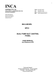
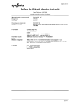
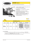
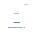
ALMA Monitor and Control Bus
Interface Specification
ALMA-70.35.10.03-001-A-SPE
Version: A
Status:
(Draft, Pending, Approved, Released, or Obsolete)
2001-09-07
Prepared By:
Name(s) and Signature(s)
Mick Brooks
Larry D’Addario
Organization
NRAO
NRAO
Date
2001-09-07
Approved By:
Name and Signature
Organization
Date
B. Glendenning
NRAO
7/22/03
Released By:
Name and Signature
Organization
Date
xxx
xxx
yyyy-mm-dd
ALMA Project
ALMA Monitor and Control Bus
Interface Specification
Doc # : ALMA-70.35.10.03-001-A-SPE
Date: 2001-09-07
Status: Draft
(Draft, Pending, Approved,Released,Superceded, Obsolete)
Page:
2 of 18
Change Record
Version
Date
Author
Reason/Initiation/Remarks
Mick Brooks
Section/Page
affected
All
A
1999/09/22
B
1999/12/09
Mick Brooks
All
Fixed block diagram to current state of
standard interface
C
2000/02/29
Mick Brooks
All
Review comments included
D
2000/04/18
Mick Brooks,
Larry D’Addario
All
Post-review comments, clarification of reset
line added
E
2001/01/17
Mick Brooks,
Larry D’Addario
All
F
2001/01/26
Mick Brooks
All
Removed details of AMBSI hardware,
merged with Timing Addendum, fixed up
maximum number of slave nodes, added
circular connector, added RS485 bus for
timing signal. First release as an ALMA-wide
specification; ALMA document number
assigned.
Comments from delta review incorporated
G
2001/02/05
Mick Brooks
All
Additional comments included from
D’Addario and Gustafsson
H
2001/09/07
Mick Brooks
All
Added specification on maximum rate of
Master transactions to a single node
I
2003/05/26
L. Cryer
All
Reformatted
J
2003/10/01
R. Marson
Title Only
Document number changed
First public release
ALMA Project
ALMA Monitor and Control Bus
Interface Specification
Doc # : ALMA-70.35.10.03-001-A-SPE
Date: 2001-09-07
Status: Draft
(Draft, Pending, Approved,Released,Superceded, Obsolete)
Page:
3 of 18
Table of Contents
1. INTRODUCTION ............................................................................................................... 4
2. M&C BUS INTERFACE .....................................................................................................5
2.1 Physical Standards ........................................................................................................5
2.1.1 Physical Layer and Media Access Protocol..............................................................5
2.1.2 Physical Interconnection...........................................................................................5
2.2 Node Connection Protocol ............................................................................................10
2.2.1 Bus Identification....................................................................................................11
2.2.2 Node Insertion and Removal ..................................................................................11
2.2.3 Message Content.....................................................................................................12
2.2.4 Error Situations .......................................................................................................12
2.2.5 Special Events........................................................................................................13
2.2.6 Reset Signal ............................................................................................................14
2.2.7 Timing Signal ........................................................................................................14
3. TIMING OF COMMANDS AND MONITOR REQUESTS ...........................................14
3.1 Definitions.....................................................................................................................14
3.2 Specification..................................................................................................................14
3.3 Discussion .....................................................................................................................17
REFERENCES .......................................................................................................................18
ALMA Project
ALMA Monitor and Control Bus
Interface Specification
Doc # : ALMA-70.35.10.03-001-A-SPE
Date: 2001-09-07
Status: Draft
(Draft, Pending, Approved,Released,Superceded, Obsolete)
Page:
4 of 18
1. Introduction
This document specifies the ALMA Monitor and Control Bus interface. Section 2 lays down the
fundamental requirements that must be met by all nodes on the bus. In Section 2.1, the method for
physical connection of nodes to the bus is given. An application level protocol to which all M&C
nodes must conform is outlined in Section 2.2. In order for a subsystem to work with the ALMA
M&C Bus, it is sufficient for the interface to conform to the standards presented in Section 2. Section
3 specifies how some bus messages may be synchronized to a precise timing signal distributed
separately.
The application level protocol is simple but implies that each M&C bus interface unit has a Node
Address in the range 0-2030 and a unique 64 bit Serial Number, which should be provided by a
component from the Dallas Semiconductor Silicon Serial Number family such as the DS18S20. The
node address may be specified by the ALMA Computing Group or could be settable on the interface
by means of a DIP switch or other appropriate means.
The ALMA M&C Bus (AMB) is envisaged as a master/slave multi-drop serial bus used for
communication with each antenna subsystem. Some subsystems destined for the central control
building will also be accessed with the AMB.
The design described herein is based on a Controller Area Network (CAN) serial bus operated in a
master/slave mode by a dedicated bus master. The application level protocol in Section 2.2 defines a
polled method for accessing slave nodes from a bus master and for communications to and from
individual slave nodes with the relevant CAN Message IDs. In the operational environment of the
ALMA telescope, the bus master will be an embedded computer running a real-time operating
system. In a laboratory testing environment, the master may be a PC or other general-purpose
computer running a user-based operating system such as some version of Windows or Unix. See [1]
for details on the rationale behind this design.
ALMA Project
ALMA Monitor and Control Bus
Interface Specification
Doc # : ALMA-70.35.10.03-001-A-SPE
Date: 2001-09-07
Status: Draft
(Draft, Pending, Approved,Released,Superceded, Obsolete)
Page:
5 of 18
2. M&C Bus Interface
2.1 Physical Standards
2.1.1 Physical Layer and Media Access Protocol
The low level protocol to be used will be the Controller Area Network, version 2.0 B as described in
[2]. The B version allows for up to 229 CAN Message IDs. The A version, which has an 11 bit
address range will not be used, but hardware used in the implementation will not preclude devices
using this format. Each CAN message is a packet with a fixed identifier (the CAN Message ID) and
exactly one transmitter node and any number of receiver nodes.
The CAN specification defines both the Physical Layer and the Media Access Layer of the ISO 7
layer protocol model.
The CAN bus will be operated at 1 Mbps, the maximum rate, for all twisted pair connected buses.
Where fiber optic media converters are used, the maximum transmission rate is 250kbps.
It is intended that a mixture of Full and Basic CAN controller implementations will be used to
address the various data rate requirements of the ALMA M&C. See [3] for a description of Full and
Basic CAN.
All monitor and control bus transactions will be initiated by the master. The remote frame
transmission request (RTR) will not be used by the bus master to gather monitor data. Instead,
monitor requests will be achieved by the bus master writing a CAN Message to the bus with no data.
The slave node responds by writing a CAN Message containing the requested data. RTR can not be
used over a range of CAN Message IDs as is intended by this protocol.
Control data is simply transmitted by the master, and the CAN acknowledge bit is used to verify
correct slave reception. Control messages must always have 1 to 8 bytes of data.
In order to meet the requirements outlined in [4], an additional higher level protocol will be
necessary for node management and to govern the transfer of data. Aspects of this protocol are
outlined in Section 2.2.
All slave nodes must use Philips 82C250 transceivers and preferentially Intel 82527 compatible CAN
controllers.
2.1.2 Physical Interconnection
The bus interconnections use differential signaling on a twisted-pair transmission line of 120 ohms
impedance [4] as defined in ISO 11898. The CAN bit timing characteristics allow for a 35 meter
maximum run length at 1 Mbps. The cable used should be double shielded. Suitable cable types for
the CAN signals are Belden type 3082A for trunk cabling and type 3084A for drop cables. Smaller
diameter cables include Belden type 3085. Whereas we also specify wires for a global reset signal
and a timing signal (as explained later), and possibly for power distribution, other cable types with
similar characteristics but with additional wires should be used.
ALMA Project
ALMA Monitor and Control Bus
Interface Specification
Doc # : ALMA-70.35.10.03-001-A-SPE
Date: 2001-09-07
Status: Draft
(Draft, Pending, Approved,Released,Superceded, Obsolete)
Page:
6 of 18
The connection of a chassis or subsystem to the bus is accomplished with a pair of connectors, male
and female, to which sections of trunk cable are connected (see Figure 3). Normally, the connectors
are 9-pin D-subminiature type as is the industry standard for CAN [8]1. Figure 1 and Table 1 show
the pinout of this connector. However, when the connection is to be exposed to the environment, an
Amphenol type MS3112E18-11S or MS3112E18-11P (socket and plug part numbers respectively)
11-pin circular connector should be used. Figure 2 and Table 2 show the pinout of this connector.
No connector type other than these two shall be used for bus trunk connections.
In the bus topology illustrated in Figure 3, the bus trunk connects subsystems or chassis with D- or
circular connectors, one of each sex. A stub line extends throughout each chassis and each local CAN
node attaches to the stub using connectors that may vary among devices and that may carry
additional device-dependent signals.
The bus requires termination at both ends with 124 Ω resistors capable of dissipating 200 mW.
1
To preserve the possibility of interoperability of the ALMA bus with commercial CAN devices, the
interconnections specified here follow those in [8] as much as possible.
ALMA Project
ALMA Monitor and Control Bus
Interface Specification
Doc # : ALMA-70.35.10.03-001-A-SPE
Date: 2001-09-07
Status: Draft
(Draft, Pending, Approved,Released,Superceded, Obsolete)
Page:
1
2
RSTA
3
4
CAN_L CAN_GND
6
RSTB
7
CAN_H
7 of 18
8
5
TIMA CAN_SHLD
9
TIMB
Figure 1: AMB D-connector pin allocations. A male connector is shown, viewed from the pin side; both
male and female connectors are used, as shown in Figure 3.
Table 1: 9-pin D-sub Connector Pin allocations
Pin
Signal
1
RSTA
2
CAN_L
CAN_GND
Global Slave Node Reset, line A
CAN_L bus line (dominant low)
CAN Ground
TIMA
CAN_SHLD
RSTB
CAN_H
TIMB
-
Timing Signal, line A
CAN Bus Shield
Global Slave Node Reset, line B
CAN_H bus line (dominant high)
Timing Signal, line B
Reserved for power distribution
3
4
5
6
7
8
9
Description
Doc # : ALMA-70.35.10.03-001-A-SPE
Date: 2001-09-07
Status: Draft
ALMA Project
ALMA Monitor and Control Bus
Interface Specification
(Draft, Pending, Approved,Released,Superceded, Obsolete)
Page:
8 of 18
A
J
CAN_L CAN_H
H
RSTB
B
TIMA
K
CAN_GND
C
G
TIMB
RSTA
L
CAN_SHIELD
D
F
E
Figure 2: AMB 11-pin Amphenol circular connector pin allocations. A male connector is shown,
viewed from the pin side; both male and female connectors are used, as shown Figure 3..
Table 2: 11-pin Amphenol Circular Connector Pin allocations
Pin
Signal
A
CAN_H
B
TIMA
TIMB
C
D
E
F
G
H
J
K
L
RSTA
RSTB
CAN_L
CAN_G
ND
CAN_SH
LD
Description
CAN_H bus line (dominant high)
Timing Signal, line A
Timing Signal, line B
Reserved for power distribution
Reserved for power ground
Reserved
Global Slave Node Reset, line A
Global Slave Node Reset, line B
CAN_L bus line (dominant low)
CAN Ground
CAN Bus Shield
The maximum stub length for a drop line from the trunk to a CAN node is 0.3 m. Bus nodes will
each provide a single connector. Trunk sections will have a male connector at one end and a female
connector at the other. Trunk connections will be passive and consist of 1 male connector and 1
female connector, with a stub line to the connector on a device.
Doc # : ALMA-70.35.10.03-001-A-SPE
Date: 2001-09-07
Status: Draft
ALMA Project
ALMA Monitor and Control Bus
Interface Specification
(Draft, Pending, Approved,Released,Superceded, Obsolete)
Page:
9 of 18
The use of additional pins for a global reset signal and for the distribution of the 48ms timing signal
is an ALMA extension to the CAN specification. Each signal will be transmitted as a differential
RS485 signal as defined in [7]. The logical details of the signals are described in Section 0 and
Section 0. The RS485 receiver in each node shall present no more than 1/4 of a unit load to the bus.
A suitable transceiver is the MAX3082 used in receive-only mode.
CAN_GND should be tied to the CAN bus zero-voltage reference within each connected node.
CAN_SHLD will be connected to the outer shield of the cable. Use of CAN_SHLD within a node is
optional; the recommended use is to connect it to local ground through a small resistor (10-100
ohms).
Provision may be made for the use of repeaters (such as optical) to extend the stub length or to create
low-emission or low-susceptibility bus segments.
Currently available transceivers limit the number of nodes on a single bus to 64. This may be
extended by the use of repeaters, or by driving several physical busses from one master while
maintaining a single logical bus. There is a logical limit of 2031 nodes per bus imposed by the
protocol defined in Section Error! Reference source not found., below.
Trunk Connectors
per CAN Spec
Trunk ~35m Max
. . .
Termination
124 ohms
Bus Master
Branch 1
Termination
124 ohms
1
Node
1.1
T-piece
Node
1.2
0.3m
max
stub
.
.
.
.
.
.
Node
1.K1
.
.
.
Branch 2
Branch L
Node
2.1
Node
L.1
Node
2.2
Node
L.2
.
.
.
.
.
.
.
.
.
Node
L.KL
Node
2.K2
(no term)
NOTES:
1.
Node connectors are not part of this specification. They may be device dependent. They also may
involve several connectors from stub → module → interface board.
2.
No limit on number of nodes per branch = Ki , provided that
L
∑K
i =1
3.
i
< N MAX , where NMAX is 2031.
Each branch typically serves a rack or large chassis. Each node is typically embedded in a
module-level assembly.
4. Any node can be removed or inserted without disturbing communication to others.
Figure 3: ALMA CAN bus topology
ALMA Project
ALMA Monitor and Control Bus
Interface Specification
Doc # : ALMA-70.35.10.03-001-A-SPE
Date: 2001-09-07
Status: Draft
(Draft, Pending, Approved,Released,Superceded, Obsolete)
Page:
10 of 18
2.2 Node Connection Protocol
In order to satisfy M&C requirements of determinism and flexibility, a protocol governing the
master/slave behavior must be implemented above the CAN protocol. Several proprietary products
exist to address this sort of problem (Device Net and SDS), but most are targeted at turn-key
industrial process control markets. In addition, there are several competing “open” protocols such as
CAL, CAN Open and CAN Kingdom. Here we adopt a simpler protocol, while attempting to
preserve interoperability with commercial products that support one of the higher level protocols. A
commercial product using CAL has been tested in conjunction with the simple protocol outlined
here.
A simple node identification protocol is outlined in the following sections which examine the most
important scenarios. Section 2.2.6 summarizes those events external to the bus system which will be
handled by this protocol.
The protocol is based on the reservation of a CAN Message ID range (one for each node) for use in
node-specific communication with the master. The node protocol retains a master/slave relationship,
with the master responsible for detecting most duplicate node address errors. This also means that
message collisions will not occur except in one case. When the master initializes the bus it
broadcasts a request for all nodes on the bus to identify themselves. Collisions may occur as nodes
try to send their Node Addresses and Serial Numbers. In normal operation, however, all message
transactions will be initiated by the master and no collisions will occur.
The Node Address for each slave node is adjustable by a DIP switch, backplane position, or other
method that allows it to be stored locally in a non-volatile manner. Each Node Address must be
unique within a single bus. It determines the range of CAN message IDs to which that node will
respond. In addition, each physical interface device used to connect a node to the bus is assigned a
permanent Serial Number which is unique throughout all ALMA hardware. It is intended that highlevel software will maintain tables from which each device's characteristics can be determined from
its Serial Number.
The following CAN Message ID usage is defined:
Usage
Bus Initialize
Available for Broadcasts
M&C Data
Node Identification
CAN Message ID
(hex)
00 00 00 00
00 00 00 01 – 00 03 FF FF
00 04 00 00 – 1F BF FF FF
First message in address range
A node uses CAN Message ID ((node address+1)*218) to identify itself and as the start of the CAN
Message ID range to which the slave responds. The CAN Message IDs in the range ((node
address+1)* 218 +1 to (node address+1)*218 + 218 – 1) are available for use by the slave. The
allocation and meaning of this range of CAN Message IDs is up to an individual slave
implementation. This allocation scheme is illustrated in the following table.
ALMA Project
ALMA Monitor and Control Bus
Interface Specification
Doc # : ALMA-70.35.10.03-001-A-SPE
Date: 2001-09-07
Status: Draft
(Draft, Pending, Approved,Released,Superceded, Obsolete)
Page:
Node Address
0
1
2
62
63
2030
11 of 18
Node Identification
CAN Message ID
00 04 00 00
00 08 00 00
00 0C 00 00
00 FC 00 00
01 00 00 00
1F BC 00 00
Node CAN Message ID
Range
00 04 00 01 – 00 07 FF FF
00 08 00 01 – 00 0B FF FF
00 0C 00 01 – 00 0F FF FF
00 FC 00 01 – 00 FF FF FF
01 00 00 01 – 01 03 FF FF
1F BC 00 01 – 1F BF FF FF
Each node therefore has 18 bits of CAN messages to respond to, and these may be mapped to
hardware devices in a node specific way. There are 11 bits used to denote the start of the slave CAN
Message ID range and this implies a maximum of 2031 slave nodes. This number is less than 2047
because the CAN specification mandates that the most significant 7 bits of the CAN ID must never
be all “1”s.
In addition, the range of CAN Message IDs up to the first slave node range is available for future
allocation of broadcast messages. At present the only broadcast defined is CAN Message ID 0, used
for the node identification sequence. Others may be allocated for use during interface discussions
with subsystem designers.
2.2.1 Bus Identification
After the master broadcasts the CAN message requesting slaves to identify themselves (CAN
Message ID 0), each slave writes to the node-specific identification CAN Message ID with its unique
Serial Number as data.
The master may detect duplicate Node Addresses if a slave tries to use a Node Address which is
already in use. A slave station may detect a duplicate Node Address if two slaves begin transmitting
to the same Node Address slot at the same time, but with different Serial Numbers. In this case the
slave with the higher Serial Number will detect a transmission error during the data section and will
cease transmitting as that node.
Slave nodes should respond to a bus initialize request within 1 ms. If the bus is idle for a period of 1
ms during the identification process, the bus master will assume that all slaves have identified
themselves and will begin normal bus operation.
This sequence may be initiated by the master at any time.
2.2.2 Node Insertion and Removal
When a node is inserted, the node immediately begins responding to transactions within its CAN
Message ID range. The master may not know that the slave node has been inserted unless it attempts
communication with the node, or issues a bus identification broadcast.
When a node is removed, the master will not notice unless it attempts transmission to the slave.
When this occurs it should flag the error and continue.
ALMA Project
ALMA Monitor and Control Bus
Interface Specification
Doc # : ALMA-70.35.10.03-001-A-SPE
Date: 2001-09-07
Status: Draft
(Draft, Pending, Approved,Released,Superceded, Obsolete)
Page:
12 of 18
2.2.3 Message Content
We distinguish two types of CAN message sent from the master, monitor requests and controls.
The AMB master will ensure that all consecutive CAN transactions to a single slave node occur at
least 300 µs apart.
2.2.3.1 Monitor Signals
Monitor data is requested by sending a CAN message with no data. (Remote transmissions frames
are not used due to the way that the CAN controllers implement CAN Message ID filtering). Note
that this implies that all control messages must have at least one byte of (possible dummy) data. The
slave node responds with a transmission of a CAN message with the same CAN Message ID and
containing the requested monitor data. Slaves must begin transmission of a response within 150 µs
of receiving a monitor request.
2.2.3.2 Control Signals
A control signal is sent by passing the data in a CAN message with one to eight bytes of data. Note
that no control message can have zero bytes of data as this indicates a monitor transaction. The
acknowledgement bit in the message trailer will inform the master that some slave detected a valid
message, but it does not indicate that it was correctly received by the destination node. Verification
of successful transmission requires a subsequent monitor request.
2.2.4 Error Situations
Transmission errors are handled by the CAN interface hardware. As CAN frames are received or
transmitted successfully, error counters in the CAN interface hardware are decremented. When errors
occur, these counters are incremented. When the counters reach 256 (excessive transmission errors),
the node goes "bus off" and ceases responding. See [1] for more details on this behavior. Entering the
bus off state will generate a hardware interrupt and the slave or master can attempt remedial action.
Slave
Automatic
Action by CAN
Hardware
Slave ceases
responding
Master ceases
transmitting
None
Master
Master
None
None
Error Condition
Detected By
Excessive transmission errors
(CAN controller bus off state)
Excessive transmission errors
(CAN controller bus off state)
Duplicate Node address
Slave
Duplicate Node address
Slave does not respond
(timeout)
Master
Action by ALMA
Software in Master
or Slave
None
Master resets its own
interface
Slave ceases
responding
Master flags error
Master flags error
ALMA Project
ALMA Monitor and Control Bus
Interface Specification
Doc # : ALMA-70.35.10.03-001-A-SPE
Date: 2001-09-07
Status: Draft
(Draft, Pending, Approved,Released,Superceded, Obsolete)
Page:
13 of 18
2.2.5 Special Events
The monitor and control bus is considered to be a real-time subsystem of its own, and the following
table outlines those events which may impinge on it and how it should react. The event list is a
detailed list of the environmental events that are of interest to the bus system. The list defines not
only the events, but also the expected system response, their arrival patterns, and the event source.
Nominal response times for each event are also given.
Event
System Response
Bus
Identification
a. Master
prompts nodes
b. slaves respond
with serial
number
Direction
IN
(OUT if
address
conflicts
detected)
Arrival
Pattern
Synchronization
Response
Episodic
Asynchronous
150 µs per
node
11 ms for
64 nodes
Episodic
Asynchronous
c. master
resolves
address
conflicts
Node Inserted
a. slave begins
responding to
in-range M&C
messages
immediately
<internal>
OUT
N/A
b. master detects
through bus
identify
Node Removed
a. master detects,
if scanning
<internal>
OUT
1s
b. slave flagged
as not
responding
CAN Failure
a. master stops
scanning
<internal>
OUT
Episodic
Asynchronous
20 ms
IN
Periodic
Synchronous
50 ms for
100
transactions
b. master flags
CAN failure
Scan Bus
c. slaves reset
Master transmits
M&C messages as
defined in table
ALMA Project
ALMA Monitor and Control Bus
Interface Specification
Doc # : ALMA-70.35.10.03-001-A-SPE
Date: 2001-09-07
Status: Draft
(Draft, Pending, Approved,Released,Superceded, Obsolete)
Page:
14 of 18
2.2.6 Reset Signal
The RS485 reset signal on the interface connector will normally be held at logic 0 (FALSE) by the
master. The receiver may be designed so that an open circuit on both lines will be interpreted as
logic 0 and a short circuit (0V) will also be interpreted as logic 0. When the signal is driven to logic
1 (TRUE) for 1.0 ms or longer, the CAN interface circuitry may be returned to its power-on state.
Any activity on the CAN lines may be ignored by the interface for the period extending from 1.0 ms
after RESET becomes TRUE until 1 ms after it returns to FALSE. The interface shall cease driving
the CAN lines and return to its power-on state within 0.5 ms of RESET returning to FALSE. The
master shall not transmit any messages on the CAN bus until at least 1.0 ms after it returns RESET to
FALSE.
This feature will be implemented on the prototype bus master and supported in the wiring of the
prototype antennas, but it may be deleted from future revisions of this specification. Device
designers should not assume its existence.
2.2.7 Timing Signal
The source of the timing signal will not necessarily be the master node of the CAN bus, but may be
some other node. The source will contain an RS485 transmitter which will drive the bus to a
quiescent state of logic 0 (FALSE), and will drive it to logic 1 (TRUE) periodically with a duty
cycle between 1% and 25%. The period is currently specified to be 48.0 ms. Use of the signal at
other nodes is optional, but each user node shall have an RS485 receiver that is designed so that an
open circuit or short circuit is interpreted as logic 0. The leading edge (0 to 1 transition) of the
signal will be accurately synchronized to ALMA array time (with a maximum error to be specified
elsewhere), but the timing of the falling edge (1 to 0) is not specified.
3. Timing of Commands and Monitor Requests
3.1 Definitions
A “timing event” (TE) is the positive-going transition of the low frequency periodic reference signal.
The time of receipt of a command or monitor request is the time that the last bit of the CAN frame is
transmitted on the bus by the bus master.
3.2 Specification
By default, every command transmitted to a device over the ALMA Monitor-control Bus (AMB) is
effective immediately upon receipt; and every monitor request should return the most recent data
available at the time the request is received. However, under some circumstances the effective times
may be different, as described in the following paragraphs. These commands are sometimes referred
to as “time critical”.
When specified in an Interface Control Document (ICD), a specific command may be considered
effective at a later time than its time of receipt. In all such cases, the command is associated with the
timing event (TE) that immediately follows receipt of the command. See Figure 4.
ALMA Project
ALMA Monitor and Control Bus
Interface Specification
Doc # : ALMA-70.35.10.03-001-A-SPE
Date: 2001-09-07
Status: Draft
(Draft, Pending, Approved,Released,Superceded, Obsolete)
Page:
15 of 18
When specified in an ICD, a specific monitor request may be required to return data that was
acquired at an earlier time. In all such cases, the monitor request is associated with the TE that
immediately precedes receipt of the request. See Figure 5.
As shown in Figure 4, the monitor/control system may begin transmission of a CAN frame carrying a
TE-related command no earlier than the occurrence of a TE, and it must complete the transmission
no later than 24 ms after that TE. That is, all such commands must be transmitted during the first
half of the 48-msec interval between TEs.
As shown in Figure 5, the monitor/control system may begin transmission of a monitor request CAN
frame no earlier than 24 ms after a TE, and it must complete the transmission no later than 4 ms
before the next TE. That is, all such monitor requests must be transmitted during a 20 ms window in
the last half of the 48-msec interval between TEs.
Increasing time: 48 ms ticks
TE
TE
TE
time associated
with command
command transmit
window
24ms
48ms
Figure 4: TE-associated command timing
ALMA Project
ALMA Monitor and Control Bus
Interface Specification
Doc # : ALMA-70.35.10.03-001-A-SPE
Date: 2001-09-07
Status: Draft
(Draft, Pending, Approved,Released,Superceded, Obsolete)
Page:
16 of 18
Increasing time: 48 ms ticks
TE
TE
TE
time associated with
monitor request
monitor request
transmit window
24ms
20ms
48ms
Figure 5: TE-associated monitor timing
4ms
ALMA Project
ALMA Monitor and Control Bus
Interface Specification
Doc # : ALMA-70.35.10.03-001-A-SPE
Date: 2001-09-07
Status: Draft
(Draft, Pending, Approved,Released,Superceded, Obsolete)
Page:
17 of 18
3.3 Discussion
In these situations, we say that the command is “associated with” the TE that immediately follows it,
or that the monitor request is “associated with” the TE that immediately precedes it. The actual
sampling time of monitor data or application time of command data is dependent on the device's
design. These may be offset from the associated TEs, if appropriate. All such details should be
given in the relevant part of an ICD.
Devices are not required to check that the timing of CAN frames complies with this specification. If
the bus master fails to comply, then the device may associate the monitor request or command with a
different TE than the one intended. If a particular device behaves in any other way (such as ignoring
a monitor request or command received outside some time limits), then this should be described in
the appropriate ICD.
ALMA Project
ALMA Monitor and Control Bus
Interface Specification
Doc # : ALMA-70.35.10.03-001-A-SPE
Date: 2001-09-07
Status: Draft
(Draft, Pending, Approved,Released,Superceded, Obsolete)
Page:
18 of 18
References
[1] ALMA Monitor and Control System, Mick Brooks, 1999-05-10
[2] “CAN Specification Version 2.0”, Philips Semiconductors Unternehmensbereich der Philips
GmbH, 1991
[3] “CAN System Engineering”, Wolfhard Lawrenz, Springer-Verlag, 1997
[4] ALMA Monitor and Control Bus Requirements, Mick Brooks, 1999-04-08
[5] The I2C-bus Specification Version 2.0, Philips Semiconductors, December 1998
[6] C167 Derivatives User’s Manual, Siemens AG, March 1996
[7] "Standard for electrical characteristics of generators and receivers for use in balanced digital
multipoint systems." EIA Standard RS-485, Electronic Industries Association, 1983.
[8] “CANopen Cabling and Connector Pin Assignment”, CiA Draft Recommendation DR-303-1,
Version 1.0, October 10 1999