1
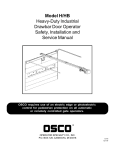
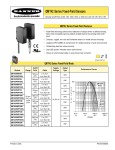
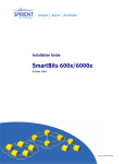
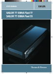
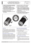
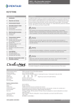
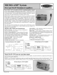
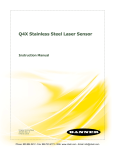
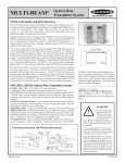
MINI-BEAM® SM2A312D
Self-contained AC-operated Diffuse Mode Sensors
• Compact, modulated, self-contained diffuse proximity mode
sensors for 24-240V dc operation
• 2-wire hookup for convenient installation
• Range to 380 mm (15 in) (referenced to 90% reflectance
white test card)
• Switch-selectable for light operate or dark operate
• SPST SCR solid-state output switches up to 300mA; low
leakage current and saturation voltage
• Rugged, epoxy-encapsulated construction: meets NEMA
standards 1, 2, 3, 3S, 4, 4X, 12 and 13; IEC IP67
• Physically and electrically interchangeable with 18 mm
barrel-type photoelectrics
Infrared, 880 nm
MINI-BEAM Diffuse Mode
Models
Range
Cable
Supply
Voltage
Output
Type
Excess Gain
Beam Pattern
Performance based on 90% reflectance white test card
1000
SM2A312D
SM2A312D
SM2A312DQD
380 mm
(15 in)
2 m (6.5 ft)
3-Pin Micro QD
24-240V ac
SPST
Solid-state
2-Wire
E
X
C
E
S
S
G
A
I
N
Diffuse Mode
100
SM2A312D
15 mm
0.6 in
Diffuse Mode
10 mm
0.4 in
5 mm
0.2 in
0
10
0
5 mm
0.2 in
10 mm
0.4 in
15 mm
1
1 mm
.04 in
0.6 in
0
10 mm
.4 in
100 mm
4 in
1000 mm
40 in
75 mm 150 mm 225 mm 300 mm 375 mm
3.0 in
6.0 in
9.0 in 12.0 in 15.0 in
DISTANCE
DISTANCE
For Standard MINI-BEAMs:
i) 9 m (30 ft) cables are available by adding suffix “W/30” to the model number of any cabled sensor (e.g. - SM2A312D W/30).
ii) A 150 mm (6 in.) long pigtail cable with attached QD connector is available by adding suffix “QDP” to the model number of any
MINI-BEAM sensor (e.g. - SM2A312DQDP). See page 5 for more information.
iii) A model with a QD connector requires an accessory mating cable. See page 8 for more information.
Printed in USA
P/N 03376L7G
MINI-BEAM® Sensors SM2A312D
MINI-BEAM Installation and Alignment
Proper operation of the SM2A312D sensor requires that it be mounted securely and
aligned properly. Excessive movement or vibration can result in intermittent or false
operation caused by loss of alignment. For best results, final-mount the SM2A312D in an
18mm-hole by its threaded barrel or use a mounting bracket (see page 6).
1) Begin with the sensor at the desired distance from the object to be sensed, and at the
approximate position where it will be mounted. The background should be as far
behind the object as possible (at least three times the distance of the sensor from the
object), and as dark a color as possible compared to the object. Ideally, the object
should present its largest reflective surface to the sensor.
Diffuse Mode Alignment
t
jec
Ob
SM2A312D
2) Switch the sensor to light-operate mode. With the object in the sensing position,
apply power to the sensor, and advance the 15-turn GAIN control to maximum
(clockwise end of rotation). The GAIN control is clutched at both ends to avoid
damage, and will “free-wheel” when either endpoint is reached.
Up
ht
Rig
If the sensor is “seeing” its reflected light, the alignment LED should be “on”. Move
the sensor up-down-right-left (include angular rotation) to find the center of
movement zone within which the LED remains lit. Reducing the GAIN setting (if
necessary) will reduce the size of the movement zone and make more precise
alignment possible.
3) Repeat the alignment motions after each GAIN reduction. When you are satisfied that
you have obtained optimum alignment, mount the sensor solidly in that position.
Increase the GAIN to maximum. Test the system by removing the object from the
sensing position. The receiver LED indicator should go “off”. If the LED indicator does
not go “off”, the sensor is reacting to light reflected from a background surface.
Reduce the GAIN setting until the alignment indicator goes “off”, plus two additional
full turns. Again place the object in the sensing position. If the alignment indicator
does not come “on”, the sensor is receiving as much or more light energy from the
background as from the object. Consider the following alternatives:
a)
wn
Do
SM2A312D
15 Turn
Gain
Adjustment
and Light/Dark
Operate Switch*
Gasketed
Acrylic Cover
move the sensor closer to the object and reduce the sensitivity (GAIN);
b) reduce background reflectivity by painting the background with flat-black
paint, or by scuffing the background or cutting a hole through it;
c)
ft
Le
Red LED lights when the
sensor's output is conducting
tilt the sensor or the background so that the sensing beam is not
perpendicular to the background.
* Note regarding Light/Dark operate switch:
• Turn switch fully clockwise for light operate (sensor outputs conduct when object is present)
• Turn switch fully counterclockwise for dark operate (sensor outputs conduct when object is absent)
page 2
MINI-BEAM® Sensors SM2A312D
MINI-BEAM AC Product Specifications
Supply Voltage and Current
24 to 240V ac (50/60 Hz), 250V ac max
Supply Protection Circuitry
Protected against transient voltages
Output Configuration
SPST SCR solid-state relay with either normally closed or normally open contact (light/dark operate
selectable); 2-wire hookup
Output Rating
Minimum load current 5 mA; maximum steady-state load capability 300 mA to 50°C ambient (122°F)
100 mA to 70°C ambient (158°F)
Inrush capability 3 amps for 1 second (non-repetitive); 10 amps for 1 cycle (non-repetitive)
Off-state leakage current less than 1.7 mA rms
On-state voltage drop ≤5 volts at 300 mA load, ≤10 volts at 15 mA load
Output Protection Circuitry
Protected against false pulse on power-up
Output Response Time
8 milliseconds on and off
“OFF” response time specification does not include load response of up to 1/2 ac cycle (8.3 milliseconds).
Response time specification of load should be considered when important.
(NOTE: 300 millisecond delay on power-up.)
Repeatability
2.6 milliseconds; Response time and repeatability specifications are independent of signal strength.
Adjustments
LIGHT/DARK OPERATE select switch, and 15-turn slotted brass screw GAIN (sensitivity) adjustment potentiometer (clutched at both ends of travel). Both controls are located on rear panel of sensor and
protected by a gasketed, clear acrylic cover.
Indicators
Red indicator LED on rear of sensor is “ON” when the load is energized
Construction
Reinforced VALOX® housing, totally encapsulated, o-ring sealing, acrylic lenses, and stainless steel screws
Environmental Rating
Meets NEMA standards 1, 2, 3, 3S, 4, 4X, 12, and 13; IEC IP67
Connections
PVC-jacketed 2-conductor 2 m (6.5ft) or 9 m (30ft) cables, or 3-pin micro-style quick disconnect (QD)
fitting are available. QD cables are ordered separately. See page 8.
Operating Temperature
Temperature: -20° to +70°C (-4° to +158°F)
Maximum Relative Humidity: 90% at 50°C (non-condensing)
Application Notes
i) ac MINI-BEAMs may be destroyed from overload conditions
ii) Use on low voltage requires careful analysis of the load to determine if the leakage current or on-state
voltage of the sensor will interfere with proper operation of the load
iii) The false-pulse protection feature may cause momentary drop-out of the load when the sensor is
wired in series or parallel with mechanical switch contacts
Certifications
VALOX® is a registered trademark of General Electric Company
page 3
MINI-BEAM® Sensors SM2A312D
MINI-BEAM AC Hookup Diagrams
AC Sensors with Attached Cable
AC Sensors with Quick Disconnect
(3-Pin Micro-Style)
rd/bk
bn
rd/wh
24-240V ac
bu
Load
24-240V ac
Load
gn
3-Pin Micro-Style Pin-out
(Cable Connector Shown)
Quick Disconnect (QD) Option
Green Wire
AC MINI-BEAM sensors are sold with either a 2 m (6.5 ft)
or a 9 m (30 ft) attached PVC-covered cable, or with a 3-pin
micro-style QD cable fitting.
Red/Black
Wire
Red/White
Wire
AC QD sensors are identified by the letters “QD” in their
model number suffix. For more information on mating QD
cables, see page 8.
MINI-BEAM Dimension Information
MINI-BEAM AC Sensor with Integral Cable
3.2 mm
(0.13 in)
12.2 mm (0.48 in)
30.7 mm
(1.21 in)
ø 3 mm Clearance (2)
24.1 mm
(0.95 in)
M18 x 1 x 15 mm Thread
(Mounting Nut Supplied)
19.1 mm
(0.75 in)
66.0 mm
(2.60 in)
page 4
1/2-20 UNF Thread
Quick Disconnect
20.0 mm
(0.79 in)
2 m (6.5 ft) Cable
Mounting Peg
(ø 6.3 mm x 2.5 mm)
MINI-BEAM AC Sensor with Quick-Disconnect
27.4 mm (1.08 in)
MINI-BEAM® Sensors SM2A312D
MINI-BEAM MODIFICATIONS
Model Suffix
Modification
Description
Example of Model
Number
W/30
9 meter (30 ft) cable
All MINI-BEAM sensors may be ordered with an integral 9 m (30 ft)
cable in place of the standard 2 m (6.5 ft) cable
SM2A312D W/30
QDP
SM2A312DQDP
Replacement Lens Assemblies
Right-Angle Reflectors
MINI-BEAM lens assemblies are field-replaceable.
MINI-BEAM right-angle reflectors are useful for tight sensing
locations. NOTE: These reflectors significantly decrease excess gain.
Model
UC-300L
Pigtail Quick
Disconnect
All MINI-BEAMs may be built
with a 150 mm (6 in) long
integral cable which is
terminated with the
appropriate QD connector.
Description
Replacement lens for
SM2A312D
Model
Description
RAR300SM
• Side mount reflector
• Profile dimension of 14 mm (0.56 in)
in the direction of the scan
RAR300FM
• Front mount reflector that attaches
directly to the threaded barrel of most
MINI-BEAMs
• Profile dimension of 34 mm (1.35 in)
in the direction of the scan
page 5
MINI-BEAM® Sensors SM2A312D
Mounting Brackets
Model
Description
R 24.1 mm
(0.95 in)
R 5.1 mm
(0.20 in)
10° (TYP)
15°
(2)
CL 31.8 mm
(1.25 in)
4.32 mm
(0.170 in)
Slot (2)
20.3 mm
(0.80 in)
20°
SMB312S
Stainless steel 2-axis, side
mounting bracket
ø 3.05 mm Slot
(0.120 in)
ø 3.05 mm
(0.120 in)
20.1 mm
(0.79 in)
90°
2.5 mm
(0.10 in)
R 3.1 mm
(0.12 in) (2)
45.5 mm
(1.79 in)
R 24.1 mm
(0.95 in)
R 5.1 mm
(0.20 in)
15.2 mm
(0.60 in)
15°
(2)
CL 31.8 mm
(1.25 in)
20°
SMB312PD
Stainless steel 18 mm barrelmounting bracket
ø 4.6 mm Slot
(0.18 in)
ø 4.6 mm
(0.18 in)
R 3.1 mm
(0.12 in) (2)
18.42 mm
(0.725 in)
40.6 mm
(1.60 in)
90°
2.5 mm
(0.10 in)
45.5 mm
(1.79 in)
4.3 mm Slot (2)
(0.17 in)
10° (2)
90°
9.1 mm
(0.36 in)
10° (2)
SMB312B
Stainless steel 2-axis, bottom
mounting bracket
2.5 mm
(0.10 in)
3.1 mm
Slot (2)
(0.12 in)
24.1 mm
(0.95 in)
8.6 mm (2)
(0.34 in)
17.3 mm (2)
(0.68 in)
ø 6.9 mm
(0.27 in)
23.4 mm
11.4 mm (0.92 in)
(0.45 in)
35.0 mm (2)
(1.38 in)
50.8 mm
(2.00 in)
CL
6 mm
(0.2 in)
6 mm
(0.2 in)
5 mm (0.2 in)
(2x)
SMB46L
15 mm
(0.6 in)
ø36 mm (1.4 in)
ø6.5 mm (0.26 in) (6x)
8 mm
(0.3 in)
16 mm
(0.6 in)
• “L” bracket
• 14 ga 316 stainless steel
65 mm
(2.6 in)
54 mm
(2.1 in)
page 6
2 mm
(.1 in)
27 mm
(1.1 in)
MINI-BEAM® Sensors SM2A312D
Mounting Brackets
Model
Description
Dimensions
CL
10 mm
(0.4 in)
34 mm
(1.3 in)
17 mm
(0.7 in)
6 mm
(0.2 in)
6 mm
(0.2 in)
SMB46S
• “S” bracket
3.5 mm
(0.14 in)
15 mm
(0.6 in)
ø36 mm (1.4 in)
ø6.5 mm (0.26 in) (6x)
8 mm
(0.3 in)
5 mm (0.2 in)
(4x)
16 mm
(0.6 in)
• 14 ga 316 stainless steel
65 mm
(2.6 in)
2 mm
(.1 in)
54 mm
(2.1 in)
27 mm
(1.1 in)
16 mm
(0.6 in)
34 mm
(1.3 in)
CL
17 mm
(0.7 in)
13 mm
(0.5 in)
3.5 mm
(0.14 in)
6 mm
(0.2 in)
SMB46U
• “U” bracket
• 14 ga 316 stainless steel
6 mm
(0.2 in)
5 mm (0.2 in)
(4x)
15 mm
(0.6 in)
8 mm
(0.3 in)
16 mm
(0.6 in)
ø36 mm (1.4 in)
ø6.5 mm (0.26 in) (6x)
16 mm
(0.6 in)
65 mm
(2.6 in)
2 mm
(.1 in)
54 mm
(2.1 in)
40.0 mm
(1.60 in)
SMB18C
• 18 mm split clamp black
VALOX® bracket
• Stainless steel mounting
hardware included
42.4 mm
(1.67 in)
13 mm
(0.5 in)
14.0 mm
(0.55 in)
2.5 mm
(0.10 in)
46.0 mm
(1.81 in)
SMB18S
• Stainless steel mounting
hardware included
70 mm
(2.8 in)
21.1 mm
(0.83 in)
30.0 mm
(1.18 in)
• 18 mm swivel, black VALOX®
bracket
27 mm
(1.1 in)
44.5 mm
(1.75 in)
M5 x 0.8
x 60 mm
Screw (2)
10.9 mm
(0.43 in)
25.4 mm
(1.00 in)
13.0 mm (0.50 in)
36.0 mm
(1.42 in)
Nut Plate
2.5 mm
(0.10 in)
Spacer
(If Required)
Nut Plate
6.4 mm
(0.25 in)
M5 x 0.8
x 60 mm
Screw (2)
page 7
MINI-BEAM® Sensors SM2A312D
Extension Cables (without connectors)
The following cables are available for extending the length of existing sensor cable. These are 30 m (100 ft) lengths of MINI-BEAM cable.
This cable may be spliced to existing cable. Connectors, if used, must be customer-supplied.
Type
Model
EC312A-100
2-conductor
Used with:
All MINI-BEAM SM2A312 ac models
Micro-Style Quick Disconnect Cables
Cable: PVC jacket, polyurethane connector body, nickel-plated brass coupling nut
Conductors: 22 or 20 AWG high-flex stranded, PVC insulation, gold-plated contacts
Temperature: -40 to +80°C (-40 to +176°F)
Voltage Rating: 250V ac/300V dc (3-pin), 125V ac/150V dc (4-pin)
Style
3-Pin
Straight
Model
MQDC-306
MQDC-315
MQDC-330
Length
2 m (6.5 ft)
5 m (15 ft)
9 m (30 ft)
Dimensions
Pin-out
ø15 mm
(0.6 in)
ø1/2-20UNF-2B
44 mm max.
(1.7 in)
Green Wire
Red/White
Wire
38 mm max.
(1.5 in)
3-Pin
Right-angle
MQDC-306RA
MQDC-315RA
MQDC-330RA
2 m (6.5 ft)
5 m (15 ft)
9 m (30 ft)
Red/Black
Wire
38 mm max.
(1.5 in)
1/2-20UNF-2B
ø15 mm
(0.6 in)
WARRANTY: Banner Engineering Corporation warrants it products to be free from defects for one year. Banner Engineering
Corporation will repair or replace, free of charge, any product of its manufacture found to be defective at the time it is returned
to the factory during the warranty period. This warranty does not cover damage or liability for the improper application of
Banner products. This warranty is in lieu of any other warranty either expressed or implied.
!
WARNING
These photoelectric presence sensors do NOT include the self-checking redundant circuitry
necessary to allow their use in personnel safety applications. A sensor failure or malfunction can result in either
an energized or a de-energized sensor output condition.
Never use these products as sensing devices for personnel protection. Their use as a safety device may create
an unsafe condition which could lead to serious injury or death.
Only MINI-SCREEN®, MULTI-SCREEN®, MICRO-SCREEN™, MACHINE-GUARD™ and PERIMETER-GUARD™ Systems, and other
systems so designated, are designed to meet OSHA and ANSI machine safety standards for point-of-operation guarding
devices. No other Banner sensors or controls are designed to meet these standards, and they must NOT be used as sensing
devices for personnel protection.
Banner Engineering Corp., 9714 Tenth Ave. No., Minneapolis, MN 55441
Telephone: (612) 544-3164
FAX (applications) (612) 544-3573