1
www.keithley.com
KI-Tool and KI-Link Software
User’s Manual
2110-921-01 Rev. A / July 2012
A
G R E A T E R
M E A S U R E
O F
C O N F I D E N C E
KI-Tool And KI-Link Software
User's Manual
© 2012, Keithley Instruments, Inc.
Cleveland, Ohio, U.S.A.
All rights reserved.
Any unauthorized reproduction, photocopy, or use the information herein, in whole or in part,
without the prior written approval of Keithley Instruments, Inc. is strictly prohibited.
All Keithley Instruments product names are trademarks or registered trademarks of Keithley
Instruments, Inc. Other brand names are trademarks or registered trademarks of their respective
holders.
Document number: 2110-921-01 Rev. A / July 2012
Table of Contents
Introduction ............................................................................................................... 1-1
Welcome .............................................................................................................................. 1-1
What is the KI-Tool?............................................................................................................. 1-1
What is the KI-Link? ............................................................................................................. 1-2
System requirements ........................................................................................................... 1-2
Operating system ...................................................................................................................... 1-2
NI-VISA Runtime ....................................................................................................................... 1-3
Obtaining the software ......................................................................................................... 1-3
Installing the software .............................................................................................. 2-1
Installing the software .......................................................................................................... 2-1
Connecting instruments to a computer ................................................................................ 2-2
Using USB................................................................................................................................. 2-2
Using GPIB ............................................................................................................................... 2-3
KI-Tool ....................................................................................................................... 3-1
Starting the KI-Tool Software ............................................................................................... 3-1
Changing the language ............................................................................................................. 3-2
Workspace ........................................................................................................................... 3-2
(1) Menu bar.............................................................................................................................. 3-3
(2) Toolbar................................................................................................................................. 3-3
(3) Instrument List ..................................................................................................................... 3-3
(4) Graph Settings ..................................................................................................................... 3-3
(5) Instrument Information ......................................................................................................... 3-4
(6) Function Panel ..................................................................................................................... 3-6
(7) Graph Display ...................................................................................................................... 3-6
Menus................................................................................................................................... 3-6
Settings ..................................................................................................................................... 3-6
Record .................................................................................................................................... 3-18
Operation ................................................................................................................................ 3-23
Tool ......................................................................................................................................... 3-24
Help......................................................................................................................................... 3-26
KI-Link ....................................................................................................................... 4-1
Overview .............................................................................................................................. 4-1
Microsoft Excel .......................................................................................................................... 4-1
Microsoft Word ........................................................................................................................ 4-14
Section 1
Introduction
In this section:
Welcome .................................................................................. 1-1
What is the KI-Tool? ................................................................. 1-1
What is the KI-Link? ................................................................. 1-2
System requirements ............................................................... 1-2
Obtaining the software ............................................................. 1-3
Welcome
Thank you for using a Keithley Instruments product. This manual provides information about the
following start-up software and utilities included with your product:
•
•
KI-Tool
KI-Link
What is the KI-Tool?
The KI-Tool software does not require programming to provide charting and graphing capabilities,
simplifying setup and basic measurement applications requiring graphical data representation. Scale,
offset, and level can be adjusted to fine-tune images for visual evaluation of signal and noise
elements over time. It also includes tabular data and Standard Commands for Programmable
Instruments (SCPI) command prompt windows for maximum flexibility. Data sets can also be saved to
disk files.
Section 1: Introduction
KI-Tool And KI-Link Software User's Manual
The KI-Tool software simulates the front-panel operation of a Keithley Instruments digital multimeter,
including the following functions:
•
•
•
•
•
•
•
•
•
•
•
•
•
DC voltage (DCV)
AC voltage (ACV)
DC current (DCI)
AC current (ACI)
2-wire resistance (2Ω)
4-wire resistance (4Ω)
Frequency (FREQ)
Period
Continuity (CONT)
Diode (
)
Resistance temperature detectors (TEMP)
Thermocouple {TCOUPL)
Capacitance (
)
The KI-Tool software allows you to quickly control the instrument over USB or GPIB (if equipped).
The KI-Tool software provides MIN, MAX, AVG, and count math functions.
What is the KI-Link?
®
®
KI-Link software provides Microsoft Word and Excel add-in tools for remotely storing and recalling
the measured values from these applications.
System requirements
Operating system
The KI-Tool and KI-Link applications run on computers with the following versions of the Microsoft
®
Windows operating system:
1-2
•
Microsoft Windows XP Home, Professional, or Tablet PC Edition with Service Pack 3 (32 bit) or
Service Pack 2 (64 bit)
•
Windows Server 2003 (32 bit and 64 bit; Service Pack 2 required for 64 bit); Windows Server
2008 or 2008 R2 (32 bit and 64 bit)
•
Windows Vista Home Basic, Home Premium, Business, Ultimate, or Enterprise with Service
Pack 2 (32 bit and 64 bit)
•
Windows 7 Starter, Home Premium, Professional, Ultimate, or Enterprise (32 bit and 64 bit)
®
®
2110-921-01 Rev. A / July 2012
KI-Tool And KI-Link Software User's Manual
Section 1: Introduction
NI-VISA Runtime
TM
TM
NI-VISA is National Instruments (NI ) implementation of the VISA standard. There are two
versions: a full version and a run-time version. The Keithley I/O Layer (KIOL) contains a licensed
version of the NI-VISA Run-Time Engine that contains only the binary files (DLLs) that allow the NIVISA drivers to operate.
If you already have NI software (such as LabVIEW™ or LabWindows™) installed, you have a valid
license that can be used with Keithley drivers and application software.
If you do not have NI software installed, you must install the KIOL to install the the drivers.
Obtaining the software
The required software is provided on the CD-ROM that came with your instrument. This software is
also available on the Keithley Instruments website (http://www.keithley.com).
2110-921-01 Rev. A / July 2012
1-3
Section 2
Installing the software
In this section:
Installing the software .............................................................. 2-1
Connecting instruments to a computer..................................... 2-2
Installing the software
To install NI-VISA:
Refer to the reference manual for information about installing NI-VISA. The reference manual is
located on the CD-ROM that came with your instrument.
Information about installing NI-VISA is also available on the Keithley Instruments website
(http://www.keithley.com).
To install the KI-Tool and KI-Link software:
The installation software is located on the CD-ROM that came with your instrument.
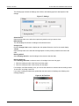
1. Run the executable file to install the software.
2. Select your language.
3. When the Keithley Instruments Software Setup wizard displays, follow the instructions to install
the software.
During the software installation, the Software Setup wizard places KI-Tool, Excel Add-In, and Word
Add-in icons on the computer desktop and in the program/start menu. The following figure shows
what the desktop icons look like:
Figure 1: KI-Tool icons
Section 2: Installing the software
KI-Tool And KI-Link Software User's Manual
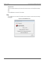
To remove the software:
If it is ever necessary to remove the software, use the Uninstall selection in the Keithley Instruments
folder under the program/start menu.
Figure 2: Uninstall
1. Click Uninstall.
2. When the Keithley Instruments Software Uninstall wizard displays, follow the instructions to
uninstall the software.
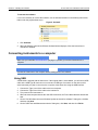
Connecting instruments to a computer
Make sure you install the NI-VISA Runtime (on page 1-3) before you connect instruments to a
computer.
Connect the instrument to the computer before starting the KI-Tool software.
Using USB
A USB cable is shipped with the instrument. If the original cable is not available, you will need a USB
cable with a USB Type B connector on one end and a USB type A connector on the other end for
each instrument you plan to connect to the computer at the same time using the USB interface.
1.
2.
3.
4.
Connect the Type A end of the cable to the host computer.
Connect the Type B end of the cable to the instrument.
Turn power to the instrument on.
When the host computer detects the new USB connection, the Found New Hardware Wizard will
start.
5. On the "Can Windows connect to Windows Update to search for software?" dialog box, click No,
and then click Next.
6. On the "USB Test and Measurement device" dialog box, click Next, and then click Finish.
2-2
2110-921-01 Rev. A / July 2012
KI-Tool And KI-Link Software User's Manual
Section 2: Installing the software
Using GPIB
GPIB is an optional interface and may not be installed on the instrument. If the GPIB interface is
available on your instrument, refer to the Reference manual that came with your instrument for
information about using GPIB.
2110-921-01 Rev. A / July 2012
2-3
Section 3
KI-Tool
In this section:
Starting the KI-Tool Software ................................................... 3-1
Workspace ............................................................................... 3-2
Menus ...................................................................................... 3-6
Starting the KI-Tool Software
Connect the instruments to the computer first, before starting the KI-Tool software. If you forget to
connect the instruments first, you can click Refresh on the Settings menu to display the instruments.
Refer to Refresh (on page 3-18) for details.
To start the KI-Tool software from the desktop:
Double-click the KI-Tool software icon, shown in the following figure. The KI-Tool software opens.
Figure 3: KI-Tool icon
If the KI-Tool software icon is not on your desktop, perform the procedure below to start the KI-Tool
software from the Windows start menu.
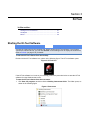
To start the KI-Tool software from the start menu:
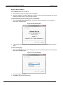
1. Click Start, All programs, and then click the Keithley Instruments folder. The folder opens, as
shown in the following figure.
Figure 4: Start menu
Section 3: KI-Tool
KI-Tool And KI-Link Software User's Manual
2. Click the KI-TOOL folder.
3. Click KI-Tool. The KI-Tool software opens.
Changing the language
By default, the KI-Tool software displays menu items in English. You have the option to change the
language to Chinese. If you select another language, the KI-Link software will display menus in the
selected language. Refer to the Help (on page 3-26) topic for information about how to change the
language.
Workspace
The workspace is the environment that appears when you open the KI-Tool software. The workspace
contains areas which provide:
•
•
Access to tools to configure instruments connected to the computer.
Access to tools and menu items to control the KI-Tool software's charting and graphing
capabilities.
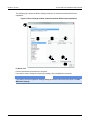
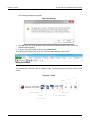
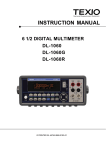
The following figure shows the KI-Tool software workspace. The workspace is divided into seven
areas, described in the following topics.
Figure 5: KI-Tool Workspace
3-2
2110-921-01 Rev. A / July 2012
KI-Tool And KI-Link Software User's Manual
Section 3: KI-Tool
(1) Menu bar
The menu bar provides menus and buttons to configure and run the KI-Tool software. The menu bar
is located at the top of the user interface. Refer to Menus (on page 3-6) for information about the
menus on the menu bar.
(2) Toolbar
The toolbar contains tools to control the KI-Tool software operation and to set up functions.
Click the start icon to start plotting data on the graph.
Click the stop icon to stop plotting data on the graph.
Click the settings icon to open the Device Settings (on page 3-7) menu.
(3) Instrument List
For each instrument connected to the computer, the Instrument List:
•
•
•
Identifies the instrument by its model number and serial number
Shows the present function and range selected
Provides a drop-down menu to select a second measurement (2ND) function, if desired
(4) Graph Settings
The Graph Settings area provides controls to scale and control the graph. The following figure shows
the Graph Settings area.
Figure 6: Graph Settings
Shift Graph
The Shift Graph control allows you to shift positions of the lines on the graph. This feature is useful
when graphing dual measurements or graphing data from multiple instruments. Use the Up and Dn
(down) buttons to position the lines on the graph display.
Each time you click a button, the graph shifts up or down by one division, changing the position of the
zero-line.
2110-921-01 Rev. A / July 2012
3-3
Section 3: KI-Tool
KI-Tool And KI-Link Software User's Manual
Y-Scale
The Y-Scale control allows you to adjust the size of the vertical axis division. Use the Up and Dn
(down) buttons to increase and decrease the span of the plots.
Offset
The Offset control allows you to apply an offset to each data point by adding or subtracting the value
entered. Enter the offset value and click the SET button.
Reading Speed
The Reading Speed control allows you to set the amount of time in milliseconds (ms) that the
instrument takes between readings. Select the Reading Speed from the drop-down menu.
X-Max
The X-Max control allows you to select the maximum number of readings that will display on the
completed graph. When you select an X-Max value, the KI-Tool software will show all the readings
until it reaches the X-Max number of readings. Then, it will show the last X-Max number of readings.
For example, if the instrument takes 1000 readings and X-Max is set to 100, the KI-Tool software will
only display 100 readings on the completed graph.
(5) Instrument Information
The Instrument Information display shows information about each instrument that is connected
including:
•
•
•
•
Model number and serial number
Selected function
Line color
The reading that the instrument is presently taking. This display changes each time the
instrument tales a reading. When the instrument is not taking readings, the display shows the last
reading taken.
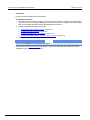
The Instrument Information display only shows information about one instrument at a time. Select the
instrument to display from the Instrument List as shown in the following figure.
3-4
2110-921-01 Rev. A / July 2012
KI-Tool And KI-Link Software User's Manual
Section 3: KI-Tool
Figure 7: Select instrument from Instrument List to display readings
2110-921-01 Rev. A / July 2012
3-5
Section 3: KI-Tool
KI-Tool And KI-Link Software User's Manual
(6) Function Panel
Select the function you want the instrument to perform by clicking the desired function button. See the
following table for a description of each function.
Button
Function
DCI
ACI
4W
PERIOD
DIODE
TCOUPL
DCV
ACV
2W
FREQ
CONT
TEMP
CAP
DC current measurement.
AC current measurement.
4-wire (Ω 4) resistance measurement.
Period measurement.
Diode ( ) test.
Thermocouple temperature measurement.
DC voltage measurement.
AC voltage measurement.
2-wire (Ω 2) resistance measurement.
Frequency measurement.
Continuity test.
RTD temperature measurement.
Capacitance ( ) measurement.
(7) Graph Display
The Graph Display area shows the readings from all connected instruments in a graphical format.
Readings will not display until you select Start Readings (on page 3-24) from the Operation menu.
Menus
The menu bar provides the following menus:
•
•
•
•
•
Settings (on page 3-6)
Record (on page 3-18)
Operation (on page 3-23)
Tool (on page 3-24)
Help (on page 3-26)
Settings
Use the Settings menu to configure device and reading settings.
The Settings menu has four selections:
•
•
•
•
3-6
Device Settings (on page 3-7)
Reading Settings (on page 3-12)
Refresh (on page 3-18)
Exit (on page 3-18)
2110-921-01 Rev. A / July 2012
KI-Tool And KI-Link Software User's Manual
Section 3: KI-Tool
Device Settings
Use Device Settings to set up the selected instrument. Alternatively, you can copy the present local
settings from the instrument. Depending on which model instrument you are setting up, the Device
Settings window may have different settings.
The following figure shows the Device Settings window for an instrument equipped with second
measurement (2ND) function capabilities.
Figure 8: Device Settings window (instrument with 2ND function capabilities)
2110-921-01 Rev. A / July 2012
3-7
Section 3: KI-Tool
KI-Tool And KI-Link Software User's Manual
The following figure shows the Device Settings window for an instrument without 2ND function
capabilities.
Figure 9: Device Settings window (instrument without 2ND function capabilities)
(1) Device List
Lists the instruments connected to the computer.
If you want to view or change an instrument's settings, click to highlight the instrument.
If you want to use the configuration settings already set from the instrument's front panel, click Get
Multimeter Settings.
3-8
2110-921-01 Rev. A / July 2012
KI-Tool And KI-Link Software User's Manual
Section 3: KI-Tool
(2) Function
Lists the functions available for the instrument.
To configure a function:
1. Click the function you want to configure. After you select a function to configure, the labels for the
drop-down menus will change depending on which function you are configuring. See the following
table for information about the labels associated with each function.
2. Configure additional settings as necessary:
•
(4) Resolution, Filter, Aperture, or Unit (on page 3-10)
•
(5) 2ND function (if equipped) (on page 3-11)
•
(6) Range (for 2ND function, if equipped) (on page 3-12)
•
(7) NPLC, Bandwidth, Aperture, Integration Time, and Type (on page 3-12)
3. Click Submit when you are finished with the configuration.
You must click Submit for the settings to take effect.
See the figure in the Device Settings (on page 3-7) section for information about what the numeric
designators in the following table indicate.
2110-921-01 Rev. A / July 2012
3-9
Section 3: KI-Tool
KI-Tool And KI-Link Software User's Manual
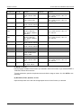
Function (2)
Label (3)
Choices
DC Voltage
Range
DC Current
Range
AUTO, 100m Vdc, 1 Vdc, Resolution
10 Vdc, 100 Vdc, 1000
Vdc
AUTO, 10m Adc, 100 Adc, Resolution
1 Adc, 3 Adc, 10 Adc
AC Voltage
Range
AC Current
Range
Resistance
(2W)
Range
Resistance
(4W)
Range
Frequency
Range
Period
Range
Continuity
Diode
TEMP
N/A
N/A
Sensor
TCOUPLE
DC Ratio
Sensor
Range
CAP
Range
AUTO 100m Vdc, 1 Vdc,
10 Vdc, 100 Vdc, 750 Vdc
AUTO, 1 Adc, 3 Adc, 10
Adc
AUTO, 100 ohm, 1K ohm,
10K ohm, 100K ohm,
ohm, 1M ohm, 10M ohm,
100M ohm,
AUTO, 100 ohm, 1K ohm,
10K ohm, 100K ohm,
ohm, 1M ohm, 10M ohm,
100M ohm,
AUTO, 100m Vdc, 1 Vdc,
10 Vdc, 100 Vdc, 750 Vdc
AUTO, 100m Vdc, 1 Vdc,
10 Vdc, 100 Vdc, 750 Vdc
N/A
N/A
PT100, D100, F100,
PT385, PT3916, NTCT,
SPRTD, USER
K, J, R, S, T, E, N, C
AUTO, 100m Vdc, 1 Vdc,
10 Vdc, 100 Vdc, 1000
Vdc
AUTO, 1nf, 100nf, 100nf,
1 μF, 10 μF, 100 μF
Label (4)
Choices
Filter
0.001 PLC, 0.006 PLC, 0.02 PLC, 0.06
PLC, 0.2 PLC, 0.6 PLC, 1 PLC, 10
PLC, 100 PLC
0.001 PLC, 0.006 PLC, 0.02 PLC, 0.06
PLC, 0.2 PLC, 0.6 PLC, 1 PLC, 10
PLC, 100 PLC
3 HZ, 20 HZ, 200 HZ
Filter
3 HZ, 20 HZ, 200 HZ
Resolution
0.001 PLC, 0.006 PLC, 0.02 PLC, 0.06
PLC, 0.2 PLC, 0.6 PLC, 1 PLC, 10
PLC, 100 PLC
Resolution
0.001 PLC, 0.006 PLC, 0.02 PLC, 0.06
PLC, 0.2 PLC, 0.6 PLC, 1 PLC, 10
PLC, 100 PLC
Aperture
0.01 Sec, 0.1 Sec, 1 Sec
Aperture
0.01 Sec, 0.1 Sec, 1 Sec
N/A
N/A
Unit
N/A
N/A
C, F, K
Unit
Resolution
C, F, K
0.001 PLC, 0.006 PLC, 0.02 PLC, 0.06
PLC, 0.2 PLC, 0.6 PLC, 1 PLC, 10
PLC, 100 PLC
N/A
N/A
(3) Range or Sensor
Lists the ranges available for the function you selected in the list of functions. If you selected TEMP or
TCOUPLE, this list will list sensors.
To make a selection, open the drop-down menu and click the range or sensor. Or, click AUTO to use
autorange.
(4) Resolution, Filter, Aperture, or Unit
Open the drop-down menu and click the appropriate choice for the function you selected.
3-10
2110-921-01 Rev. A / July 2012
KI-Tool And KI-Link Software User's Manual
Section 3: KI-Tool
(5) 2ND Function (if equipped)
The Model 2110 is equipped with a dual-measurement feature. It allows a user to configure the
instrument to take two different measurements in a sequential order and to display the results
simultaneously.
If you are using the KI-Tool software with an instrument that provides dual-measurement capability,
the second measurement function (2ND) settings display in the Device Settings window. If you are
using an instrument without this capability, no 2ND function settings are present.
See the following table for information about the 2ND functions available for each main measurement
function.
The main measurement function you select determines which 2ND functions are available. In the
following table, the symbol (•) indicates which 2ND functions are available for each main
measurement function. Diode and continuity testing are not available as a 2ND functions.
2ND function
Main function
DCV
DCI
•
•
•
•
•
•
•
•
•
DCV
ACV
•
DCI
•
•
ACI
Ω2/Ω4
ACV
•
FREQ
(VOLT)
•
•
ACI
FREQ
(CURR)
•
PERIOD
(VOLT)
•
•
PERIOD
(CURR)
CAP
TEMP
(RTD)
TCOUPL
•
•
•
•
Ω2/Ω4
•
FREQ (VOLT)
•
•
•
FREQ (CURR)
PERIOD (VOLT)
•
•
•
•
•
•
•
•
PERIOD (CURR)
•
•
•
•
•
•
•
CAP
•
TEMP (RTD)
•
TCOUPL
•
•
•
•
•
•
•
•
•
•
•
Open the drop-down menu and click the appropriate choice for the 2ND function you selected.
If you want to stop taking two different measurements, click NONE to remove the 2ND function.
2110-921-01 Rev. A / July 2012
3-11
Section 3: KI-Tool
KI-Tool And KI-Link Software User's Manual
(6) Range (for 2ND Function, if equipped)
Lists the ranges available for the 2ND function you selected in the list of 2ND functions. The 2ND
function you select determines what ranges are available.
Open the drop-down menu and click the appropriate choice for the 2ND function you selected. Refer
to (5) 2ND function (if equipped) (on page 3-11) for information about selecting a 2ND function.
Click AUTO to select autorange.
(7) NPLC, Bandwidth, Aperture, Integration Time, and Type
Open the drop-down menu and click the selection you want.
(8) Submit
Click the Submit button when you are finished configuring the KI-Tool software to take readings. If
you do not click Submit, the settings will not take effect.
(9) Get Multimeter Settings
Use the Get Multimeter Settings button to retrieve the present instrument configuration to the
Device Settings window.
(10) Exit
Use the Exit button to close the Device Settings window.
Reading Settings
Use Reading Settings to configure the following KI-Tool software settings:
•
•
•
Store the readings from multiple devices simultaneously.
Display the readings in the color you select.
Save the readings to a record.
Reading Mode
Select Single Device (on page 3-13) or Multiple Devices (on page 3-14).
3-12
2110-921-01 Rev. A / July 2012
KI-Tool And KI-Link Software User's Manual
Section 3: KI-Tool
Single Device
Click Single Device to configure the instrument to take readings on one device only. The KI-Tool
software displays the following dialog box.
Click the Change Color and 2ND Change Color buttons (if present) to change the color(s) of the
graph display.
Figure 10: Reading Mode (single device)
2110-921-01 Rev. A / July 2012
3-13
Section 3: KI-Tool
KI-Tool And KI-Link Software User's Manual
Multiple Devices
The Multiple Device selection is only available when multiple instruments are connected to the
computer. The maximum number of devices you can connect is four.
To configure more than one instrument:
1. Select Multiple Devices. The KI-Tool software displays the Reading Settings dialog box.
2. Click the >> and << buttons to toggle between the settings for different instruments. See the
following figures for the Reading Setting dialog boxes for a computer with two instruments.
Figure 11: Reading Settings for first instrument
3-14
2110-921-01 Rev. A / July 2012
KI-Tool And KI-Link Software User's Manual
Section 3: KI-Tool
Figure 12: Reading Settings for second instrument
2110-921-01 Rev. A / July 2012
3-15
Section 3: KI-Tool
KI-Tool And KI-Link Software User's Manual
Change Color
Configure the KI-Tool software to display the graphs for each instrument in the color you choose.
Not all instruments support Dual Measure. Refer to (5) 2ND function (if equipped) (on page 3-11) for
details. You cannot select Dual Measure; the KI-Tool software enables Dual Measure when you
select 2ND function. If Dual Measure is enabled, you will be able to select a color to graph the 2ND
function.
To select a color:
1. Click Change Color, the KI-Tool software displays the color palette as shown in the following
figure.
2. Select the color.
3. Click OK.
If a 2ND Change Color button is on the Reading Settings dialog box, repeat steps 1 through 3 to
change the 2ND color.
Figure 13: Color palette
3-16
2110-921-01 Rev. A / July 2012
KI-Tool And KI-Link Software User's Manual
Section 3: KI-Tool
Save
Use Save to record readings. You can save up to 10 records.
To record readings:
1. Select the Save check box.
2. Select one of the numbered records for recording readings in the drop-down menus.
3. If you are recording from multiple instruments, refer to Multiple Devices (on page 3-14) for
information about toggling between the different devices.
Figure 14: Select Save to record readings
The KI-Tool software date and time stamps previously recorded records in the following format:
yy / mm / dd -- hh : mm : 00
Where:
•
yy = last two digits of the year
•
mm = month
•
dd = day of the month
•
hh = hours in 24 hour format
•
mm = minutes
•
ss = seconds
2110-921-01 Rev. A / July 2012
3-17
Section 3: KI-Tool
KI-Tool And KI-Link Software User's Manual
Refresh
If you connect additional instruments to your computer after starting the KI-Tool software, click
Refresh to add them to the instrument list.
Exit
Click the Exit button to close the KI-Tool software.
Record
Use the Record menu to view and chart previously saved records. Refer to Save (on page 3-17) for
information about saving records.
The Record menu has two selections:
•
•
View Record (on page 3-18)
Chart Record (on page 3-20)
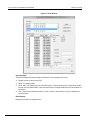
View Record
Use the View Record selection to view previously saved records.
The KI-Tool software displays a maximum of 10 previously recorded readings on the Record List.
Click a record to select and display it.
Use the buttons in the View Record dialog box to perform the following operations on the records:
•
•
•
3-18
Refresh Record - Update the display.
Delete - Delete a saved record.
Output to CVS - Export the saved record to CSV format. Microsoft Excel uses this format.
2110-921-01 Rev. A / July 2012
KI-Tool And KI-Link Software User's Manual
Section 3: KI-Tool
Figure 15: View Record
Record Display
The Record Display lists the following information for each reading in the record:
•
•
•
Record number (in the first column)
•
Time - the time the reading was taken in hours, minutes, and seconds. The time is displayed in
24-hour format.
Value - the reading value
Value_2ND - the reading value for the 2ND function. If the instrument is not configured for a 2ND
function, the field will be blank. If the instrument does not support a 2ND function, the field will not
be present.
Data Quantity
Displays the number of readings taken.
2110-921-01 Rev. A / July 2012
3-19
Section 3: KI-Tool
KI-Tool And KI-Link Software User's Manual
MAX MIN AVG
Displays the following information:
•
•
•
MAX - the value of the maximum (highest) reading in the record.
MIN - the value of the minimum (lowest) reading in the record.
AVG - the average value of all readings in the record.
Data Filter
The Data Filter allows you to set upper and lower boundaries to sort the readings.
To use the data filter:
1. Enter the upper limit in the HI Limiter field.
2. Enter the lower limit in the LO Limiter field.
3. Click Search to start the filter.
Range Browsing
Use the Range Browsing menu to select a range of readings within the record to view.
Exit
Click the Exit button to close the View Record window.
Chart Record
Use Chart Record to draw graphs of previously saved readings.
The following figure shows the Chart Record window. The window has seven areas described in the
following topics:
3-20
2110-921-01 Rev. A / July 2012
KI-Tool And KI-Link Software User's Manual
Section 3: KI-Tool
Figure 16: Chart Record
Settings
Use the Settings area of the Chart Records window to set up the following charting operations:
•
•
•
Select a record to chart.
Display the records in the color you select.
Set the Y-scale for the chart.
2110-921-01 Rev. A / July 2012
3-21
Section 3: KI-Tool
KI-Tool And KI-Link Software User's Manual
The following figure shows the Settings area. Refer to the following topics for descriptions of the
settings.
Figure 17: Settings
Select Record
Open the drop-down menu and select a previously saved record you want to chart.
Data Quantity
This field displays the number of readings in the selected record.
Change Color
Click the Change Color button to display the color palette.Select the color for the record display.
Y-Scale
Open the drop-down menu and select the appropriate Y-Scale (vertical) measurement unit for the
chart.
Drawing with all
Select Drawing with all to use all readings in the record to draw the chart.
Drawing data from
Select Drawing data from to choose a section of readings in the record to graph.
1. Enter the reading number of the first entry for the graph.
2. Enter the reading number of the last entry for the graph.
For example, if the Data Quantity is 22, you can use this selection to start the chart at reading number
12 and end it at reading number 20.
If you enter a reading number that is greater than the total number of readings, the following error
message displays.
Figure 18: KI-Tool Error
3-22
2110-921-01 Rev. A / July 2012
KI-Tool And KI-Link Software User's Manual
Section 3: KI-Tool
Graph
The KI-Tool software graphs the data and displays the chart.
Drawing
Use the Drawing button to instruct the KI-Tool software to create the chart based on the selections in
the Settings.
2ND Drawing (if equipped)
If the record you are charting has a 2ND function measurement, use the 2ND Drawing button to plot
the 2ND function measurement readings.
Clear
Use the Clear button to reset the display to blank.
Exit
Use the Exit button to close the Chart Record window.
Data Selection Slider
Use the Data Selection Slider to step through data points.
Operation
The Operation menu instructs the instrument to start or stop taking measurement readings.
The Operation menu has three selections:
•
•
•
Multiple Readings (on page 3-24)
Start Readings (on page 3-24)
Stop Readings (on page 3-24)
2110-921-01 Rev. A / July 2012
3-23
Section 3: KI-Tool
KI-Tool And KI-Link Software User's Manual
Multiple Readings
Multiple Readings keeps the chart from updating while the instrument is taking readings. The KI-Tool
software stores the readings in a file and does not display dynamic curves.
Multiple Readings takes a specified number of measurements and puts them into the specified lists.
When you select Multiple Readings, stop is enabled while data is being taken.
The following figure shows the Multiple Readings dialog box. The following topics describe the fields
in the Multiple Readings dialog box.
Figure 19: Multiple readings
Instrument List
Use Instrument List to select the instrument to use to take the readings.
Number of Readings
Enter the number of readings you want the instrument to take. The minimum number of readings you
can take is 1 and the maximum number is 50,000.
Record List
Open the drop-down menu to select the record that the instrument will use for storing readings.
Start Readings
Click the Start Readings button to start the measurements.
Stop Readings
Click the Stop Readings button to stop the measurements.
Tool
Use the Tool menu has a command control submenu that provides an interactive dialog box for
sending SCPI commands to the instruments connected to your computer. Refer to your instrument's
Reference manual for information about SCPI commands.
3-24
2110-921-01 Rev. A / July 2012
KI-Tool And KI-Link Software User's Manual
Section 3: KI-Tool
Command Control
The following figure shows the Command Control dialog box. The following topics describe the fields
in the Command Control dialog box.
Figure 20: Command Control
Device List
The Device List drop-down menu lists the instruments connected to the computer. Open the dropdown menu and click the instrument you want to configure, operate, or command.
Send String
Enter the SCPI commands in the Send String dialog box.
Query
Use the Query button to send the command in the Send String field to the instrument. The KI-Tool
software displays any information the instrument returns in the String Received display area.
The Query command performs both a write and a read operation.
Write
Use the Write button to send the command in the Send String field to the instrument.
Read
Click the Read button to retrieve data from the output buffer of the selected instrument.
2110-921-01 Rev. A / July 2012
3-25
Section 3: KI-Tool
KI-Tool And KI-Link Software User's Manual
String Received
The KI-Tool software displays any information the instrument returns in the String Received display
area.
Exit
Click the Exit button to close the KI-Tool software.
Help
Use the Help menu to view the KI-Tool software version information, view this manual, and change
the language.
Figure 21: About Multimeter Tool
3-26
2110-921-01 Rev. A / July 2012
KI-Tool And KI-Link Software User's Manual
Section 3: KI-Tool
To select the language:
1. Click the Language tab on the About dialog box. The KI-Link software displays the language list
shown in the following figure.
Figure 22: KI-Tool language
2. Click the language you want.
3. Click OK to close the About dialog box.
2110-921-01 Rev. A / July 2012
3-27
Section 4
KI-Link
In this section:
Overview .................................................................................. 4-1
Overview
Before you can start using the KI-Link software, you must install the software and connect
instruments to your computer. Refer to the Getting started (see "Installing the software" on page 2-1)
section for information about installing the software.
The KI-Link software works with:
•
•
Microsoft Excel (on page 4-1)
Microsoft Word (on page 4-14)
Both of these products must be installed on the same computer as the KI-Tool software.
Microsoft Excel
Starting the KI-Link software add-in for Microsoft Excel
To start the software:
1. Double-click the KI-LINK Excel Add-In icon on the desktop.
Figure 23: KI-Link EXCEL Add-In icon
Section 4: KI-Link
KI-Tool And KI-Link Software User's Manual
The following message may appear:
Figure 24: Message
2. Click OK. If you are using an earlier version of Microsoft Office than Office 2007, the KI-Link
software toolbar displays.
3. If you are using Office 2007 or 2010, click the Add-Ins tab.
The following figure shows how the KI-Link software toolbar displays in Excel 2010.
Using the toolbar
The toolbar provides easy access to all of the KI-Link software features.
The following figure shows the KI-Link software toolbar. The following topics describe the icons on the
toolbar.
Figure 25: Toolbar
4-2
2110-921-01 Rev. A / July 2012
KI-Tool And KI-Link Software User's Manual
Section 4: KI-Link
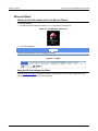
About the KI-Link software
Use the About button on the toolbar to:
•
•
View information about operating system compatibility.
Select the language. The default language is English. If you select another language, the KI-Link
software will display menus in the selected language.
To view information about operating system compatibility:
1. Click the About KI-Link software button. The KI-Link software displays the About dialog box
shown in the following figure.
Figure 26: About dialog box
2. If you want to select a language, use the following procedure or click the OK button to close the
dialog.
To select the language:
1. Click the Language tab on the About dialog box. The KI-Link software displays the language list
shown in the following figure.
Figure 27: KI-Tool language
2. Click the language you want.
3. Click OK to close the About dialog box.
2110-921-01 Rev. A / July 2012
4-3
Section 4: KI-Link
KI-Tool And KI-Link Software User's Manual
Connect to Device
The KI-Link software can only control one instrument at a time.
Use the Connect to Device dialog to:
•
•
•
Connect instruments
Disconnect instruments
Search the device list for instruments that are connected
To connect an instrument:
1. Click the Connect to Device
icon. The KI-Link software displays the Select Device dialog
box, shown in the following figure.
Figure 28: Select Device dialog box
4-4
2110-921-01 Rev. A / July 2012
KI-Tool And KI-Link Software User's Manual
Section 4: KI-Link
2. Click the Search button. The KI-Link software displays the Select Device dialog box showing the
Identified Instruments on My Computer list, shown in the following figure.
Figure 29: Identified Instruments on My Computer list
3. Select the device you want to connect.
4. Click the Connect button. After your computer connects to the instrument, the KI-Link software
displays the Key Lock
icon in the Instrument field to indicate that the instrument is connected.
Figure 30: Key Lock icon indicates connected instrument
2110-921-01 Rev. A / July 2012
4-5
Section 4: KI-Link
KI-Tool And KI-Link Software User's Manual
To disconnect an instrument:
1. If the Select Device dialog box is not open, click the Connect to Device
icon to open it.
Figure 31: Device Connect
2. Click the Disconnect button. After your computer disconnects from the instrument, the KI-Link
software removes the Key Lock
icon from the selected instrument.
3. You can connect another instrument on the list, or click the OK button to exit the Select Device
dialog box.
To search the device list for instruments that are connected:
Click the Search button. The Select Device dialog box displays all instruments connected to your
computer.
4-6
2110-921-01 Rev. A / July 2012
KI-Tool And KI-Link Software User's Manual
Section 4: KI-Link
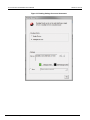
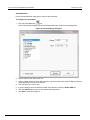
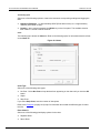
Setup Multimeter
Use the Setup Multimeter dialog box to configure the instrument.
To configure the instrument:
1. Click the Setup Multimeter
icon.
The KI-Link software displays the Device Settings dialog box, shown in the following figure.
Figure 32: Device Settings dialog box
2. Select a function from the function list.
3. Use the default values for range and resolution or open the drop-down menus to display a list that
shows appropriate values for the function.
4. Click the values you want to use.
5. If you are taking a second measurement with the instrument, check the Enable 2ND box.
6. Click the Submit button when you are finished selecting values.
7. Click Exit to close this dialog box.
2110-921-01 Rev. A / July 2012
4-7
Section 4: KI-Link
KI-Tool And KI-Link Software User's Manual
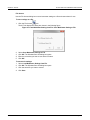
File Access
Use the File Access dialog box to save instrument settings to a file and restore them for use.
To save settings to a file:
icon.
1. Click the File Access
The KI-Tool displays the dialog box shown in the following figure.
Figure 33: Load Multimeter Setting from File / Save Multimeter Setting to File
2.
3.
4.
5.
Select Save Multimeter Settings to File.
Click OK. The Windows Save As dialog box opens.
Enter the name that you want to use as the file name.
Click OK.
To restore the settings:
1. Select Load Multimeter Settings from File.
2. Click OK. The Windows Save As dialog box opens.
3. Click the saved file you want to restore.
4. Click Save.
4-8
2110-921-01 Rev. A / July 2012
KI-Tool And KI-Link Software User's Manual
Section 4: KI-Link
Get Single Reading
Use Get Single Reading to obtain a single reading from the instrument and select the cell in which to
save the reading.
Click the Get Single Reading
icon to display the Get Single Reading dialog box.
Figure 34: Get Single Reading
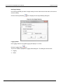
Logging Charts
Use Logging Charts to set up data logging and display it on a chart.
Click the Logging Charts
icon.
The KI-Link software displays the Logging Charts dialog box. This dialog box has two tabs:
•
•
Logging
Charts
2110-921-01 Rev. A / July 2012
4-9
Section 4: KI-Link
KI-Tool And KI-Link Software User's Manual
Logging
The following figure shows the Logging tab. Refer to the following topics for information about the
fields on the Logging tab.
Figure 35: Data logging
Begin Logging Data
Select one of the following options to instruct the instrument to take readings and log the data.
•
•
•
Immediately - right now
At Time - at a specific time in the future
External Trigger - when someone presses the LOCAL key on the front panel
If you select At Time, enter the time as follows:
1. Select the date by positioning the cursor in the month, day, or year field and using the up and
down arrows to increase or decrease digits. The date format is mm/dd/yyyy.
Where: mm = 2-digit month, dd = day, and yyyy = 4-digit year
2. Enter the time in 24-hour format by positioning the cursor in the hours, minutes, or seconds field
and entering the digits. The maximum time you can set is 23 hours, 59 minutes, and 59 seconds.
Where: hh = hours, mm = minutes, ss = seconds.
With Interval Of
Enter the interval time in the following format: hh/mm/ss
Where: hh = hours, mm = minutes, ss = seconds
•
•
4-10
The maximum interval time is 23 hours, 59 minutes, and 59 seconds.
The minimum interval time can be set 0.5 seconds.
2110-921-01 Rev. A / July 2012
KI-Tool And KI-Link Software User's Manual
Section 4: KI-Link
Terminating Upon
Select one of the following options to instruct the instrument to stop taking readings and logging the
data.
•
Number of Readings - 1 to approximately 65535 (Excel 2003 or later) or 1 to approximately
1048575 (Excel 2007 or later)
•
Duration - when someone presses the LOCAL key on the front panel. The available duration
time is within 1 second to 65535 seconds.
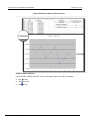
Chart
The following figure shows the Chart tab. Refer to the following topics for information about the fields
on the Chart tab.
Figure 36: Charts
Chart Type
Select one of the following chart types:
•
No Chart - Select No Chart to keep the data from appearing on the chart until you click the OK
button.
•
•
Graph
Strip Chart
If you select Strip Chart, enter the number of data points.
Refer to the Examples (on page 4-12) topic for information about what the different types of charts
look like.
Place Chart In
Select one of the following print/display options for the chart:
•
•
Separate Sheet
Same Sheet
2110-921-01 Rev. A / July 2012
4-11
Section 4: KI-Link
KI-Tool And KI-Link Software User's Manual
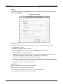
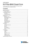
Examples
This topic shows some examples of charts.
Figure 37: Strip chart example
Figure 38: Measured data on the same sheet
4-12
2110-921-01 Rev. A / July 2012
KI-Tool And KI-Link Software User's Manual
Section 4: KI-Link
Figure 39: Measured data on different sheets
START, PAUSE, and STOP
Use the START, PAUSE, and STOP icons to control data capture to the KI-Link software.
•
•
•
Use
to start.
Use
to pause.
Use
to stop.
2110-921-01 Rev. A / July 2012
4-13
Section 4: KI-Link
KI-Tool And KI-Link Software User's Manual
Microsoft Word
Starting the KI-Link software add-in for Microsoft Word
To start the software:
1. Double-click the KI-LINK Word Add-In icon on the desktop. Word opens.
Figure 40: KI-LINK Word Add-In icon
2. The toolbar displays.
If there is an Add-Ins tab, click it to display the toolbar.
Figure 41: Toolbar
Using the KI-Link software for Word
Refer to Using the toolbar (on page 4-2). The KI-Link software for Word toolbar operation is very
similar to the KI-Link software for Excel operation.
4-14
2110-921-01 Rev. A / July 2012
Specifications are subject to change without notice.
All Keithley trademarks and trade names are the property of Keithley Instruments, Inc.
All other trademarks and trade names are the property of their respective companies.
A
G R E A T E R
M E A S U R E
O F
C O N F I D E N C E
Keithley Instruments, Inc.
Corporate Headquarters • 28775 Aurora Road • Cleveland, Ohio 44139 • 440-248-0400 • Fax: 440-248-6168 • 1-888-KEITHLEY • www.keithley.com
12/06