1
Distributed by MicroDAQ.com, Ltd.
www.MicroDAQ.com
(603) 746-5524
TABLE OF CONTENTS
1.0 INTRODUCTION
1.1
1.2
1.3
1.4
1.5
1.6
1.7
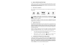
CHART SPEED TO SAMPLE SPEED
REVIEWING DATA
ZOOMING AND CONDITIONING DATA
CUSTOMIZING
TRIGGERING
THE GRAPHICS LCD DISPLAY
OTHER GRAPHIC MODES
2.0 INSTALLATION AND SETUP
2.1
2.2
2.3
2.4
2.5
2.6
UNPACKING
2.1.1
Initial Inspection
2.1.2
Unpacking Procedure
2.1.3
Detected Damage
2.1.4
Equipment Return
2.1.5
Storage
INSTALLATION
2.2.1
Panel Mounting
CONNECTION
2.3.1
Power Connections
2.3.2
Input Signal Connections
2.3.3
Relay Output Connections
2.3.4
Digital Input
2.3.5
Ethernet Connection (Option)
2.3.6
USB Port (Option)
2.3.7
Cleaning
INPUT SCALING
ALARMS
2.5.1
Alarm Types
2.5.2
Setting Alarms
2.5.3
Alarm Indication
MEMORY CARDS
2.6.1
Care of the Data Cards
2.6.2
Card Storage Capacity and Data Type
3.0 BASIC OPERATING INSTRUCTIONS
3.1
3.2
3.3
3.4
3.5
BASIC MODE OF OPERATION
VIEWING HISTORIC DATA
COMPRESSING AND EXPANDING DATA (TREND VIEWING)
ZOOMING DATA (AMPLIFICATION)
MENU MODE
3.5.1
EXIT!
3.5.2
ALARM RESET!
3.5.3
RECORD MODE
3.5.2
CURSOR ID!
3.5.3
VIEW FILE
3.5.4
CARD STATUS!
3.5.5
SAMPLE RATE
3.5.6
PASSWORD (PROTECTION)
3.5.7
ADV. SETUP (ADVANCED SETUP - See Section 4)
3.5.8
DISPLAY ADJ (ADJUST)
3.14 EVENT TRIGGERING
3.15 STATUS LINE INDICATORS
Distributed by MicroDAQ.com, Ltd.
1
www.MicroDAQ.com
(603) 746-5524
4.0 ADVANCED SETUP
4.1
4.2
4.3
4.4
4.5
4.6
4.7
4.8
4.9
4.10
CHANNEL SETUP
ALARMS
RELAYS
DISPLAY
DATA CARD
CLOCK
BEEPER
SAMPLE TRIGGER
RECORD TRIGGER
EXTERNAL INPUT
5.0 MISCELLANEOUS
5.1
5.2
CALIBRATION
SPECIFICATIONS
APPENDICES
APPENDIX A
APPENDIX B
APPENDIX C
APPENDIX D
UNITS LABEL CHARACTERS
ERROR AND INFORMATION MESSAGES
MASTER RESET
RE-PROGRAMMING FIRMWARE
SAFEGUARDS AND PRECAUTIONS
Read and follow all instructions in this manual carefully, and retain this manual for future
reference.
Do not use this instrument in any manner inconsistent with these operating instructions
or under any conditions that exceed the environmental specifications stated.
This instrument is not user serviceable. For technical assistance, contact the sales
organization from which you purchased the product.
Monarch Instrument’s Limited Warranty applies. Warranty Conditions, Registration and
Extended Warranty coverage available online at www.monarchinstrument.com.
Distributed by MicroDAQ.com, Ltd.
2
www.MicroDAQ.com
(603) 746-5524
WEEE NOTICE
In order to comply with EU Directive 2002/96/EC on Waste
Electrical and Electronic Equipment (WEEE):
This product may contain material which could be hazardous to human
health and the environment. DO NOT DISPOSE of this product as unsorted
municipal waste. This product needs to be RECYCLED in accordance with
local regulations, contact your local authorities for more information. This
product may be returnable to your distributor for recycling - contact the
distributor for details.
Para obedecer con EU Directiva 2002/96/EC en el Desecho el Equipo Eléctrico
y Electrónico :
Este producto puede contener la materia que podría ser la salud humana perjudicial para y el
ambiente. NO se DESHAGA de este producto el desecho municipal como no clasificado.
Estas necesidades del producto para SER RECICLADAS de acuerdo con las regulaciones
locales, contactan su administración local para más información. Este producto puede ser
retornable a su distribuidor para reciclar - contacta el distribuidor para detalles.
Afin de respecter la directive européenne 2002/96/EC sur l’Equipement
Electronique et les Déchets Electriques :
Ce produit pourrait contenir des matières qui peuvent être dangereuses pour la santé de
l’homme et de l’environnement. Ne pas jetter ce produit dans un container municipal
inapproprié. Ce produit doit être recyclé en accord avec les arrêtés locaux; contacter les
autorités locales pour plus de renseignements. Ce produit peut être renvoyé au distributeur
pour recyclage - Contacter votre distributeur pour plus de details.
Um den Vorschriften der EU-Direktive 2002/96/EC bezueglich elektrischer
und elektronischer Abfallstoffe nachzukommen:
Dieses Produkt kann Materialien enthalten, welche gesundheitsgefaehrdend und
umweltschädlich sind. Dieses Produkt DARF NICHT wie unsortierter Hausmuell entsorgt
werden. Dieses Produkt muss gemaess den oertlichen Bestimmungen recycled werden,
bitte kontaktieren Sie die lokalen Behoerden fuer weitere Informationen. Sie koennen dieses
Produkt zum Recycling an Ihren Haendler zurueckgeben, bitte kontaktieren Sie den Haendler
fuer weitere Details.
AJW112/09/05 REV03
MLK 12/15/05 REV04
Distributed by MicroDAQ.com, Ltd.
3
www.MicroDAQ.com
(603) 746-5524
1.0 INTRODUCTION
The DC1250 is the next generation Solid State Data Recorder / Panel Indicator. This
instrument has all the capability of a traditional paper recorder - variable chart speeds, the
ability to review historic data, see trends and more, with a number of specific exceptions - NO
PAPER to jam, no ink to smudge and no pens to clog or break. The data is stored in a
Compact Flash memory card, which can be easily transported.
Of course it does all the regular functions a lot better, and the data can be transferred directly
into reports, spreadsheets or analysis programs. Data can be examined and archived on any
Windows XPTM compatible machine and can be printed out in various formats as required.
This instrument has two universal inputs so it can measure voltage, current, thermocouples
and RTDs by simply selecting them from the menu. It also has two potential free alarm output
contacts and an isolated digital input. The display can be user configured to graphics, digital
or a combination. Maximum data storage is 2 Gigabytes. Communication options include
USB and Ethernet ports.
Things are done a little differently in a paperless recorder and there are a few new concepts
that you may need to become familiar with. There are more features and functions in this unit
than you will probably use. It is recommended that you read this manual in its entirety before
attempting to use the instrument.
The balance of this introduction will attempt to introduce some of the more unique features of
this paperless recorder.
1.1
CHART SPEED TO SAMPLE SPEED
A major difference between paper and paperless is SAMPLE SPEED, which is analogous to
CHART SPEED in the paper recorder. There is an apparent chart speed, the rate at which
the samples appear to move across the Graphics Display, but unlike paper recorders the
display is made up of discrete data points, each of which is a distinct sample of the data
being measured. The rate of movement across the screen is thus a direct function of the
sample rate. The major factor in deciding what sample rate to select is knowing how much
data is enough. In a paper recorder a chart speed of 1 inch per hour is fine for a process that
does not vary very quickly but would result in a thick blur if trying to record a 1Hz sine wave.
Unlike a paper recorder, every point recorded by the paperless recorder is uniquely
identifiable, no matter how dense it appears on the screen. It is always better to have too
much data than to have too little. The only consideration is the amount of space used in the
memory card.
To relate chart speed to sample rate we need to consider how we plan to reproduce the data.
The graphic LCD display has a density of 70 pixels (data points) per inch; a typical dot matrix
printer has 180 pixels per inch and a laser printer 300 pixels per inch. Thus to fill one inch of
the display in one hour we need to sample at a rate of 70 samples per hour, a little over once
per minute, however if this is now printed on a laser printer it will fill less than 1/3 of an inch. It
is the amount and quality of the data that counts. Another advantage of the paperless
recorder is that it can sample internally at 100 samples per second (one every 0.01 seconds).
These samples can be averaged or peaks or valleys can be detected and then this data can
be stored at the chosen sample rate.
Trial and experience will yield the best sample speeds for the application. Start with a faster
sampling rate than you think you will need; you can always slow it down in the future. As a
rule of thumb, one sample every 10 seconds should give the equivalent information that 1
inch per hour of chart paper would.
Distributed by MicroDAQ.com, Ltd.
4
www.MicroDAQ.com
(603) 746-5524
1.2
REVIEWING DATA
One of the biggest features of this recorder is its ability to show historic data and trends. The
data on the graphics screen can be rewound like a tape recorder, scrolling back in time,
displaying past data on the screen while still recording data in real time.
The data can also be compressed on screen, showing a whole day or week's worth of
recording on one screen, enabling trends or irregularities to be spotted easily. A data cursor
can be moved around the screen to uniquely identify samples in both time and amplitude.
Refer to the section 3 for the specifics on reviewing data.
1.3
ZOOMING AND CONDITIONING DATA
The recorder acquires data with greater resolution than can be displayed on the screen. The
user has the ability to ZOOM in to amplify the data either 2 or 4 times, equivalent to using a
magnifying glass on the display. These ZOOM windows can be scrolled up or down to cover
the entire data spectrum. The vertical scale automatically adjusts to the zoom level and
position to enable resolution of minor changes in input signal.
The recorder also acquires data at a rate faster than what may be displayed on the screen.
The user can set the sampling rate from 100 samples per second down to 1 sample every 10
minutes. When sampling slower than 100 samples per second, the recorder can be
programmed to record the average, maximum or minimum values. Thus if a sample rate of 1
sample per minute is chosen, the recorder will still sample internally at 100 samples per
second while computing the average or detect and store either the maximum (peak) value or
minimum (valley) value, depending on the mode programmed. It will then store this value
when the minute is up. Unless required otherwise, it is recommended that the average value
be used for recording since this will tend to filter or smooth the data.
1.4
CUSTOMIZING
There are many operating features and parameters that the user can program. All settings
are stored in nonvolatile memory and are recalled each time the unit is powered on. The
display can be scaled to read in engineering units, and the trace can be labeled accordingly
with up to three alphanumeric characters. Four alarms are fully user programmable and can
be associated with either channel or the external input. The Alarm levels can be set in the
engineering units of the display, the sense of the alarm, the type and the deadband or
hysteresis can be individually set for each alarm. Optional relay outputs can be assigned
independently to each alarm. A reset delay feature is also available.
There are other features which may be programmed by the user including the time stamping
mode, either real time or elapsed time, clock update rates, file names, beeper operation etc.
(Refer to Section 4 – Advanced Setup)
1.5
TRIGGERING
The recorder has the ability to change sampling speeds and stop or start recording as a
result of a triggered event. This event may be tied to any of the four internal alarms or
optionally to an external signal. This enables the unit to monitor a process without recording
or to record at a slow speed to conserve card space. When an external event or internal
alarm condition occurs, the unit will begin recording or change to a higher sample rate for the
data of interest.
Distributed by MicroDAQ.com, Ltd.
5
www.MicroDAQ.com
(603) 746-5524
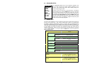
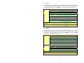
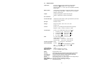
1.6
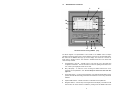
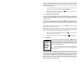
THE GRAPHICS LCD DISPLAY
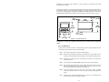
K
L
J
M
H
N
G
P
F
E
A
B
D
C
DC1250 Front View showing TREND Display
The above diagram is a representation of the recorder in the TREND mode. The alpha
characters around the border point to various features of the unit and are described below.
Not shown are the MENUS which pop up over the display. The menus are in the form of
those shown in Sections 4 and 5. The numbers in brackets below refer to the section that
covers the topic in detail.
A
CompactFlash™ card slot – manually insert a card into the unit to store data and
configuration information. Can also be used as a means of updating the firmware in the
unit. Cards up to 2 Gigabytes in size can be used.
B
Busy LED (Red) – on when the unit is recording and blinks whenever the unit is
accessing the CompactFlash™ card. Do not attempt to remove the card when this
light is on.
C
Power LED (Green) – on during normal operation. If the optional internal battery pack is
present, this LED will blink during power failure to indicate the unit is running off internal
batteries.
D
Optional USB interface – enables connection to a Windows XP compatible PC.
E
Navigation buttons – used to set up and navigate around the display. The buttons are all
dual function; the second function is initiated by holding down the MENU button while
Distributed by MicroDAQ.com, Ltd.
6
www.MicroDAQ.com
(603) 746-5524
pressing one of the other buttons. The second function is printed on each button.
F
Date and Time – shows the actual time of day (real time). The time is displayed user
selectable in 12 or 24 hour format. The user can also select European or American
formats and auto daylight savings adjustment.
G
Right hand edge of the graphics area in which the traces are displayed. This is the
vertical scale area designated by the scale values at the top, center and bottom of the
scale. The most recent data that is displayed in digital form at the top of the display (J) is
against the right edge of this scale and moves left with time - the most recent data is to
the right and the oldest data is to the extreme left. New data appears against this margin
and the oldest data disappears off the screen at the extreme left. The graphic cursor (K)
will start against this right edge.
H
Vertical Scale Identifier – the scale alternates between Channel A and Channel B. This
displays the Channel Tag and the Engineering units. The values against the scale
change in sympathy with the channel display.
J
Digital Window – shows the values for each Channel including the Channel identifier or
tag, the actual value and the engineering units. Channel A is displayed on the left and
Channel B on the right. This window displays the absolute digital value of the
instantaneous (last) reading for the channel, and is the sample against the vertical scale
of the graphics display (G), unless the cursor is active, in which case it shows the value
at the point the cursor intersects the trend line.
K
Cursor – displayed when activated in the cursor ID mode. This cursor can be moved
using the left ◄ and right ► arrow buttons. The values in the digital window (J) are the
values at the point the cursor intersects the trend line.
L
Date/Time Axis Delimiter – dashed vertical lines placed at equal increments along the
Horizontal axes (Time). The Date/Time stamp beside the line indicates the exact
position of the line. Both date and time may be shut off or relocated vertically. These
lines move with the trace at a speed dependent on the sampling speed. (Section 4.4)
M
Channel B Trace – the graphic representation of Time (horizontal) versus Amplitude
(vertical). This line is shown solid to distinguish it from the Channel A trace, which is
shown as a dotted trend line. The line format is user configurable.
N
Graphic TREND Window – shows the channel traces, which may be compressed,
expanded, zoomed, scrolled and halted.
P
Status Icons – these icons appear at various times to indicate the status of the unit and
the display. From left to right they are:
•
The numbers 1,2,3 and 4 are the ALARM indicators - one for each alarm. The
numbers are present when the alarm is enabled and will blink if the alarm is in
an alarm condition.
•
The X indicates the status of the EXTERNAL INPUT and is present when the
external input is present.
•
The
icon indicates the display is zoomed. The vertical scale indicates the
current values. The display can be scrolled up and down when zoomed using
the Up ▲ and Down ▼ arrow buttons.
•
The
icon indicates the display is compressed. The horizontal time
stamps indicate the current compressed values. The display can function
normally in compressed mode, may be paused or the user can scroll back and
forth using the left ◄ and right ► arrow buttons.
•
The H indicates the display is in the HOLD condition. While in HOLD, the
trends do not update. The display enters the HOLD condition when the ID
Cursor (K) is present or the user scrolls in the horizontal direction using the
Distributed by MicroDAQ.com, Ltd.
7
www.MicroDAQ.com
(603) 746-5524
left ◄ and right ► arrow buttons. Exit the HOLD mode by pressing the MENU
button.
DO NOT INSERT OR REMOVE THE COMPACT FLASH CARD
WHILE THE BUSY LED IS ON!
1.7
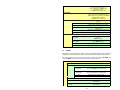
OTHER GRAPHIC MODES
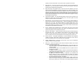
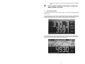
In addition to the full screen trend mode shown section 1.6, there are two additional graphic
display modes.
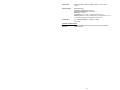
The Dual Digital mode, as shown below, enables both channels to be shown as Digital values
similar to a digital panel meter. The user has the option of showing the displays in normal or
reverse video (shown) modes, and the display can be set to blink on Alarm Condition.
The other Graphic mode is a split screen with the trend in the top half and the digital display
in the lower half as shown below. When selecting this mode, Channel B is the default digital
value, which is set in the Advanced Setup menu (see Section 4).
Distributed by MicroDAQ.com, Ltd.
8
www.MicroDAQ.com
(603) 746-5524
2.0 INSTALLATION AND SETUP
2.1
UNPACKING
2.1.1 Initial Inspection
Exercise care when unpacking the instrument from the shipping carton. The instrument is
packed in a custom cardboard box to prevent damage during normal transit. If damage to
the shipping carton is evident, ask the carrier’s representative to be present when the
instrument is unpacked.
2.1.2 Unpacking Procedure
To unpack your Recorder, first remove the cardboard retainer and instrument from the
shipping carton. Check the box for the following contents - The Recorder, two locking
bars, two 6-32 x ½" screws, AC power supply wall unit (unless the unit is the isolated DC
model) and this manual.
2.1.3 Detected Damage
Remove the instrument from the plastic bag and check for damage if any. Also check that
the unit is as ordered. If damage is detected after unpacking the instrument, immediately
report any damage to the shipping agent and re-pack the instrument for return it to the
factory as described in the following section.
2.1.4 Equipment Return
Before returning a damaged or malfunctioning instrument to the factory for repair, contact
the sales organization from which you purchased the instrument. A Return Merchandise
Authorization (RMA) number must be obtained from the factory before returning an
instrument for any reason.
2.1.5 Storage
For prolonged storage before installation, re-pack the Recorder in the shipping container
and store in a cool, dry area. We do not recommend storage of the Recorder for more
than one year. If longer storage time is required, contact the factory for additional storage
information.
2.2
INSTALLATION
The instrument is intended to operate in the following environment:
Indoor Use Only
Installation Category II per IEC 664
Pollution Degree Level II per IEC61010-1
Altitude up to 2,000 m
Temperature -10 °C to 50 °C operating per IEC61010-1
Humidity Maximum relative humidity 80% for temperatures up to
31 °C decreasing linearly to 50% relative humidity at 40 °C
Recorder Power 9.0 +0.5V dc @ 4.5VA (unless indicated otherwise on the unit)
AC Mains Supply (External adapter) 100 - 240 Vac ~ 50/60 Hz
NOTE: The recorder is designed to be panel mounted and as such should be considered as
permanently connected. Disconnection from the supply must be possible via a customer
supplied switch or circuit breaker. This disconnection device must be included in the panel
Distributed by MicroDAQ.com, Ltd.
9
www.MicroDAQ.com
(603) 746-5524
installation and should be clearly marked, in close proximity to the Recorder and easily
accessible to the operator.
The Recorder is sized to fit in a standard ¼ DIN panel cutout of 92 x 92 mm (3.62 x 3.62 in.)
and requires 140mm (7.5 inches) behind panel depth not including space for power and input
source cable. The thickness of the panel is immaterial, but panels thicker than .125 inch will
require that the locking bars be cut down. Actual dimensions are shown below in Figure 2.1:
0.30
[7.62]
5.22
[132.46]
3.78
[96.00]
3.78
[96.00]
4.07
[103.38]
0.41
[10.41]
3.60
[91.44]
0.15
[3.81]
Figure 2.1 Recorder Dimensions
WARNING: Do not use this instrument in any manner inconsistent with these operating
instructions or under any conditions that exceed the environmental specifications
stated.
2.2.1 Panel Mounting
The Recorder should be mounted in a vertical panel to ensure proper operation. Ensure
you have the proper clearances and proceed as follows:
2.2.1.1 Cut a panel opening 96 mm x 96 mm (3.62 x 3.62 in.).
2.2.1.2 Remove any packaging material from the Recorder. Always handle the unit
carefully to avoid damaging the LCD display or scratching the display surface.
2.2.1.3 Remove the locking bars from the Recorder enclosure by removing the
captivating screws
2.2.1.4 Insert the Recorder, rear end first, through to front of the panel opening.
2.2.1.5 With the Recorder held firmly in place against the panel, install one of the
locking bar assemblies by sliding the locking bar notch into the groove on the
side of the Recorder enclosure as shown in Figure 2.2.
2.2.1.6 Insert the retaining screw into the rear of the groove. Using a Phillips
screwdriver, tighten the screw until the locking bar is just pressing against the
panel.
2.2.1.7 Install the other locking bar assembly into the groove on the opposite side of
the Recorder enclosure and tighten as before.
Distributed by MicroDAQ.com, Ltd.
10
www.MicroDAQ.com
(603) 746-5524
2.2.1.8 Using the screwdriver, tighten both screws so that the Recorder is held firmly
in place. Do not over tighten.
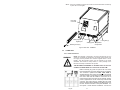
DC Power
Connector
Relay Outputs
Digital Input
Retaining Screw (2)
Locking Bar (2)
Analog Inputs
Temperature
Compensator
Fig 2.2 Rear View - Installation
2.3
CONNECTION
2.3.1 Power Connections
WARNING
NOTE: The Recorder is designed to be panel mounted and as such
should be considered as permanently connected. Disconnection from
the supply must be possible via a customer supplied switch or circuit
breaker. This disconnection device must be included in the panel
installation and should be clearly marked, in close proximity to the
Recorder and easily accessible to the operator.
THE RECORDER IS DESIGNED TO OPERATE ON 9 Vdc. DO NOT
CONNECT AC MAINS DIRECTLY TO THE UNIT AT ANY TIME
Before connecting any power or inputs to the unit, ensure
that all signal wires and power cables are free of potential.
The unit itself is powered from 9Vdc +0.5V 4.5VA as
standard although other options are available. The external
wall power supply is a high efficiency switcher that will work
from 100 to 240 Volts AC 50/60 Hz. Check the unit to
ensure that the power and inputs are as expected. The DC
power is applied to the unit via a three-way screw terminal
connector. The power supply is supplied with two tinned
leads, the positive lead is identified by the RED shroud over
the wire. The third connection is for system GROUND. You
will require a small flat-head screwdriver. Connect the
Fig 2.3
Distributed by MicroDAQ.com, Ltd.
11
www.MicroDAQ.com
(603) 746-5524
power and signal wires accordingly, noting carefully all polarities. Ensure that the unit is
properly grounded to a suitable ground within the cabinet.
Identify the power connector on the rear panel in the top left corner. The power source
required is clearly marked, DC with the specific voltage level. (Refer to Figure 2.3).
Loosen the screws on the terminal block and insert the exposed conductor cable from the
power supply below the screws, under the metal plate. Ensure that the insulation is flush
with the terminal block. If it is too long, remove the cable, trim and reinsert. Tighten the
screw to firmly hold the cable. Ensure the ground wire is connected and properly
grounded at the other end. If you are not using the supplied wall power supply, follow the
same procedure carefully identifying the positive supply line. The unit is protected against
reverse polarity but not against substantial over voltage.
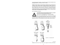
2.3.2 Input Signal Connections
The maximum input on any input channel is 25 Volts dc. Voltages
higher than this may permanently damage the unit.
Ensure the unit is unplugged before connecting any inputs.
There are two universal analog inputs – Channel A and Channel B,
each is programmed independently of the other. Inputs can be voltage
or current (50mA max using an external shunt), thermocouples, RTD’s or TTL compatible
pulse inputs. Isolation is between inputs and the rest of the system. The channels are not
isolated from each other. Connection detail for the various inputs is shown in Figure 2.4.
Figure 2.4 – Connection Detail
When connecting the signal wires, keep polarities correct. Also, if inputs are nonisolated, ensure there are no high common mode voltages and maintain ground integrity.
Distributed by MicroDAQ.com, Ltd.
12
www.MicroDAQ.com
(603) 746-5524
The screw terminals are marked on the rear panel - there are four connections per
channel. The high or positive signal marked IN+, and a low or common signal marked IN-.
The terminal marked Vo is the Auxilliary voltage output used to drive external sensors at
+5Vdc and a maximum of 30mA. The terminal marked I+ is the 1mA current required for
RTDs or resistors. Any screen or shield (often the braided wire) should connect directly to
the system ground and is used to shield the low level input signals from induced noise
pick up.
Connect the signal wires to the terminal block in the manner described above. Use wire of
adequate gauge to carry the signal. The mA input requires the use of an external 250
ohm shunt (Part No. 1034-2500-001). Thermocouples should be connected with special
thermocouple wire of the same type as the input; the terminal block is the reference
junction. Connect any sheath or braid to the GROUND connection. RTD's have an
additional wire, the current source, which is connected to the terminal marked I+. See
Figure 2.4.
WARNING: All unused inputs must have all contacts commoned togther.
CAUTION: Never run signal and power or control wiring together in the same conduit.
This is to prevent possible recording error due to induced signals between lines.
Route signal wires away from power wires at the rear panel.
NOTE: Ground cable shields at one end only to eliminate the possibility of interference
due to ground loop currents. When grounded transducers are used, the shield should
be grounded at the sensor end only.
2.3.3 Relay Output Connections
WARNING
To prevent the possibility of electrical shock, use extreme
caution when wiring contact output connections. Hazardous
potentials may exist on contact output terminals that are floating
with respect to instrument ground. WIRES FROM REMOTE
SOURCES MAY CONTAIN DANGEROUS POTENTIALS. ENSURE
ALL POWER SOURCES ARE DISCONNECTED BEFORE WIRING
RELAY CONTACTS.
The relay contacts are rated for AC or DC operation (Maximum recommended voltage 30 Volts.) Each relay has a set of potential free contacts. There is no polarity to the
terminals; it is a normally open contact that closes in alarm condition. These contacts are
internally suppressed for EMI/RFI and High Voltage transients resulting from Inductive
loads. The relays may be programmed as fail safe, which means they are energized in
the “off” condition. This way if the power should fail the relays will open into the alarm
condition.
2.3.4 Digital Input
The digital input is optically isolated and requires an external dc supply of 5 to 12Vdc at
20mA in order to operate. The input is via the DIGITAL INPUT + and – terminals. The connection is the COMMON for the external input, while the + is the input for the positive
supply.
The digital input may be used as an External Trigger to stop or start recording, or may be
used to change the sampling speed. Thus the unit can be set to record only when a
conveyor is running for example. The External Trigger may also be linked internally to the
optional Relay Output. This could be used as a remote "record active" indicator. Refer to
Sections 4.3 and 4.10.
2.3.5 Ethernet Connection (Option)
Distributed by MicroDAQ.com, Ltd.
13
www.MicroDAQ.com
(603) 746-5524
The Ethernet Connection is an option and will be installed only if specifically ordered. It is
a 10MHz TCP/IP port that allows the user to program the recorder remotely, start or stop
recording and download real time data.
Refer to the separate manual that is supplied with the ethernet interface option.
2.3.6 USB Port (Option)
The USB Port is an option and will be installed only if specifically ordered. It is a serial
connection to a PC that allows the user to program the recorder remotely, start or stop
recording and download real time data.
Refer to the separate manual that is supplied with the USB interface option.
2.3.7 Cleaning
The unit may be cleaned by wiping with a soft cloth. The front panel and display / keypad
may be wiped with a slightly damp soft cloth containing soapy solution or a mild
detergent. Do not use any lemon based (citric acid) product to clean the display /
keypad. NOTE: THE UNIT IS NOT WATERTIGHT.
2.4
INPUT SCALING
The input to the recorder is often a standard process variable (e.g. voltage) rather than the
actual units being measured (e.g. pressure).
There are a number of custom conversions available in the unit to take care of special inputs
such as thermocouples and RTDs, which need special scaling and linearization. These are
preset in the unit and require no modification. There is also the capability to customize any
input variable that has a linear relationship to the measured variable. The relationship
between the required variable and the input variable must satisfy the constraint
y = mx + c
where y is the value to be displayed and recorded, x is the input variable (typically volts or
milliamps DC), m is the scale factor which defines the relationship between the input and the
displayed variable and is a constant (linear relationship), and c is a constant offset variable
that may be positive or negative.
This facility to scale the input is found in the ADVanced SETUP menu and is available to
each channel independently in dual channel units. Here the user can easily scale the input
and set the displayed units using three alphanumeric characters.
The scaling is achieved in the unit in the CHANnel X SETUP option (X = A or B) in the
ADVanced SETUP menu. First set the displayed LO SCALE, which may be positive, negative
or zero. Then set the displayed HI SCALE for the full-scale input. The unit will then
automatically compute the scale factor and offset.
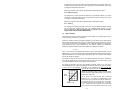
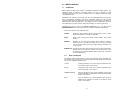
5
Setting the engineering units is done in the same menu
location using the CHAN UNITS option to set the three
alphanumeric characters.
4
INPUT
VOLTS
3
2
1
0
0
-62.5
(OFFSET)
125
250
PSI
Distributed by MicroDAQ.com, Ltd.
Let us assume we have an input from a pressure
transducer of 1 to 5 volts DC, corresponding to real
world units of zero to 250 PSI (Pounds per Square Inch
of pressure). Assume we choose the 0 to 5 volt input.
The actual output span of the transducer is 4 volts, with
1 volt = 0 PSI and 5 volts = 250 PSI. This is equivalent
to 62.5 PSI per volt. The LO SCALE which is the "0" volt
14
www.MicroDAQ.com
(603) 746-5524
value is equivalent to -62.5 PSI and should be set to this value, and the HI SCALE is set to
"250". The engineering units are set to "PSI". The display will now show zero to 250 PSI for 1
to 5 Volts input. The linear scaling is shown in Figure 2.5 on the previous page.
2.5
ALARMS
The recorder has four programmable internal alarms with dual relay output. The alarms can
be associated with either analog input channel, can be set as high or low, latching or nonlatching with or without lockout capability. Each relay has a set of potential free normally open
contacts (Form A - SPNO) that are accessible from the rear panel via screw terminal
connections. Alternatively the relays can be set to the failsafe mode, normally closed (Form B
– SPNC). The relays can be assigned to any, all or none of the alarms. Refer to section 4.2
and 4.3.
2.5.1 Alarm Types
A high alarm is active when the input is greater than the setpoint. A low alarm is active
when the input is less than the setpoint. A latching alarm will remain set once activated
and must be reset by the operator. Note that the alarm condition should be removed
before resetting the alarm or the alarm will activate and latch again. A non-latching limit
will set on alarm condition and automatically reset once the alarm condition is removed. A
differential, known as hysteresis or deadband can be introduced so that once an alarm is
set (at the setpoint), the input must go beyond the deadband before the alarm resets.
This prevents the output relays from chattering in borderline conditions. The deadband is
set in absolute units and adds to the setpoint in a low alarm, or subtracts from the
setpoint in a high alarm. By way of example, if the setpoint is 100, the hysteresis
(deadband) is set to 5, and the alarm is a high type and non latching, then the alarm will
activate when the input exceeds 100 and will remain active until the input drops below 95
(100 minus 5). Alternatively the user can set a reset delay from 1 to 255 seconds. This
delay must time out once an alarm condition has been removed before the alarm will
reset.
Lockout prevents an alarm from activating until the setpoint has been traversed in the
opposite sense by the input. For example, if we were measuring pressure and had a low
alarm set at 100, we may not wish the alarm to be active on start up when the pressure
may be low or zero. We really wish to monitor a low pressure situation once our target
pressure has been reached, say 150. The lockout prevents the alarm activating at
startup. The alarm remains deactivated until the input exceeds the setpoint. At this point
the alarm arms and any time from this point on that the input drops below the setpoint,
the alarm will activate as normal.
2.5.2 Setting Alarms
Setting and configuration is done in the Advanced Setup Menu.
The alarm setpoints are set in the same units as the inputs and may be different for each
channel. When setting the actual setpoint value, the value may be incremented in steps
other than what is expected (unit steps). This is due to the fact that the input is converted
into a digital value with a finite resolution. It is not possible to set a setpoint value that
cannot be resolved by the internal microprocessor. Select the closest value to the exact
value you require; it will always be with 0.5%. The same applies when setting the
deadband.
Note that when configuring the alarms, there is no correlation between inputs, alarms and
relay outputs. These are user defined. Each alarm can be assigned to only one input
channel.
When setting up each alarm channel, the user should DISABLE the alarm so that
parameters may be changed WITHOUT AFFECTING THE RELAYS. This is done in the
Distributed by MicroDAQ.com, Ltd.
15
www.MicroDAQ.com
(603) 746-5524
ALARMS menu by selecting the ENABLE option so that no
appears to the left of this
option. Once everything is set, select ENABLE once more to activate the alarm, indicated
by the presence of the . (Refer to Section 4.2)
When setting up alarms, you may get unexpected results from the relays if they are
enabled. Ensure there is nothing connected to the relays that could result in an
accident due to random closing of the relays during setup and always DISABLE the
alarm as described above. Make the changes and then re-enable the alarm.
There are many different ways the alarms can be set up. All the alarms can be assigned
to a single channel and may be of the same type giving for example a various degrees of
high warning and ultimately a high shutdown indication. Also, the relays may be assigned
to any combination of alarms. This would allow a single relay output to indicate any alarm
active. The combinations are endless.
2.5.3 Alarm Indication
There are three indications of alarm condition: the relay outputs, visual icons on the
display and audible alarm.
When an alarm is armed and functioning, it is indicated by a small "1", "2", "3" or "4" in
reverse video on the bottom left hand side of the graphic display. These status indicators
remain on as long as the alarm is enabled. If an alarm is triggered (in alarm condition),
the status indicator will blink and the internal beeper will sound. The beeper can be
permanently disabled from the Advanced Setup Menu - BEEPER - ALARMS - OFF.
The relays close on an alarm condition, assuming they have been set up correctly. The
relays can be set as fail-safe by reversing the logic of the alarms (Advanced Setup Menu
- RELAYS - FAILSAFE).
2.6
MEMORY CARDS
The memory cards used are standard CompactFlash™ cards. We recommend the use of
INDUSTRIAL GRADE cards. The cards are keyed and can only go into the recorder right
side up. The largest capacity card that can be accommodated is 2 Gigabytes.
2.6.1 Care of the Data Cards
Do not expose the cards to direct sunlight or extremes of temperature for any length of
time. Do not expose to moisture. Do not bend or twist. Avoid high static discharge. Mail in
suitable packaging to avoid postal damage. When transporting, use an anti-static bag or
the plastic enclosure in which the card is supplied.
2.6.2 Card Storage Capacity and Data Type
Depending on what else is stored on the card (e.g. configurations files, other data files),
data storage capacity can be roughly calculated by the following formulas:
Number of samples is card size divided by 4.4. The time that it will take to fill a card is
roughly the number of samples divided by the sample rate. For example, a 32MB card will
hold roughly 32,000,000 divided by 4.4 = 7,272,727 samples. At 5 samples per second
this is 1,454,545 seconds or 404 hours or approximately 16.8 days.
Distributed by MicroDAQ.com, Ltd.
16
www.MicroDAQ.com
(603) 746-5524
If you show the Card Status window (MENU - CARD STATUS), it will indicate how much
time is left on the card. It also displays the current Filename that is being used for
recording.
The files on the card are in DOS standard format and can be managed on any
Windows™ based machine with a CompactFlash™ reader - internal or external. The
content of the files is in proprietary binary format and requires special software to read the
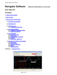
data. All units are supplied with the DataChart Navigator Software, which allows the data
to be exported to Excel.
Distributed by MicroDAQ.com, Ltd.
17
www.MicroDAQ.com
(603) 746-5524
3.0 BASIC OPERATING INSTRUCTIONS
The Basic mode of operation encompasses those functions that would be done on a routine
basis and relate primarily to viewing and reviewing data with some use of the menu system.
The advanced mode, while technically still simple to operate, involves setting up the unit and
would typically need to be done only once.
3.1
BASIC MODE OF OPERATION
Basic operations are all done using the five buttons on the front panel (shown below) and the
first level menu.
Each arrow button has dual functions. The second function is activated by pressing and
holding the MENU (2nd Function) button and then pressing any of the other buttons. The 2nd
function of each button is denoted by the text under the arrow symbol. (EXPAND,
COMPRESS, ZOOM + and ZOOM -).
The unit need not be recording to the memory card in order to manipulate data. The data
available however is dependent on how long the unit has been operating, the sample rate
and the buffer or memory card size.
3.2
VIEWING HISTORIC DATA
Any data that is not currently visible on the screen is historic data. To view past data, the left
(◄) and right (►) arrow buttons are used to rewind (◄) or fast forward (►) the data
(scrolling). When rewinding, data will be retrieved from the memory card or from the internal
buffer and is available as far back as the start of recording. When fast forwarding, data is
available up to real time. The time and date stamp on the screen indicates the relative time of
the samples being viewed.
Viewing by scrolling is limited to the file (or files) created since recording was manually
started via the RECORD MODE Menu - ON. It is possible to view data from other files of
previously recorded data (or even data recorded on another machine). See Section 3.8.
At any stage during the rewind or fast forward process, the screen can be restored
to current or real time display by pressing the MENU button.
When the data on screen is not current, an .H. appears on the status line to
indicate that the rewind or compress mode is active and the data is on Hold.
3.3
COMPRESSING AND EXPANDING DATA (TREND VIEWING)
In order to view data trends, it is often necessary to pack more data onto the screen than is
normally visible in real time. To compress the data, press and hold the MENU (2nd Function)
key and then press the COMPRESS (►) key. Each time this key is pressed the amount of
data on the screen will double up to a maximum of 32 times (equivalent to 5 sequential key
presses). Once compressed, data can be rewound and fast forwarded as described in the
previous section. The data can be expanded back after being compressed by pressing and
holding the MENU key and then pressing the EXPAND (◄) button.
Distributed by MicroDAQ.com, Ltd.
18
www.MicroDAQ.com
(603) 746-5524
Note that compression displays peak values (both high and low). Thus even though data is
compressed, all amplitude information is present on the display. At compressions of 16 times
or greater, the redraw time of data on the screen slows down due to the large amounts of
data that must be manipulated.
At any stage during the compression or expansion process, the screen can be
restored to current or real time display by pressing the MENU button.
When the data on screen is compressed, a →← appears on the status line to
indicate that the compress mode is active.
3.4
ZOOMING DATA (AMPLIFICATION)
As a result of the small display area available, it is not always possible to see small changes
in amplitude of the recorded signals even though the resolution of the internal converters can
measure it. To overcome this problem you can ZOOM in on a portion of the graph and get
increased resolution.
To ZOOM in and amplify the graph, press and hold the MENU key, press the ZOOM+ (▲)
button and then release both buttons. The display will zoom in by 2. Note that the scale units
change to reflect the increased zoom level. There are three zoom levels available: x1, x2 and
x4.
To decrease the zoom level (or zoom out), press and hold the MENU key, press the ZOOM(▼) button and then release both buttons.
Note that when zoomed in at any zoom level, the (▲) and (▼) buttons will move the graph
relative to the window enabling viewing of any part of the graph within the zoom window.
Once in a zoom level, all functions are operational on the zoomed display.
When in a zoom mode, the zoom level is indicated by a ↑↓ icon on the status line.
No indication indicates Real Time (X1).
To exit the zoom mode, zoom out as far as possible until the ↑↓ icon disappears.
3.5
MENU MODE
EXIT!
….. .
ALARM RESET!
RECORD MODE..
CURSOR ID!
VIEW FILE..
CARD STATUS!
SAMPLE RATE..
PASSWORD..
ADV.SETUP..
DISPLAY ADJ..
At any time when in normal view mode, pressing the MENU button will
bring up the user menu as shown to the right. Note that the menu "pops
up" over the graphics display. The unit continues to record and will not
lose data. There is also a time out option that will return a menu display
back to a graphic display after a period of inactivity. (Refer to Section
4.4 DISPLAY - MENU TIMEOUT).
When the menu is active, the Left Arrow (◄) and Right Arrow
(►) buttons act as ESCAPE keys to return to a previous level without
activating any function.
The user moves about the menu using the Up Arrow (▲) and Down Arrow (▼) buttons. The
current selection is always highlighted in reverse. To select a function, simply move to it with
the (▲) and (▼) buttons and then press the MENU button once. To go back a level without
activating any function, simply press the (◄) or (►) buttons. Note that the menu has more
options than can be displayed at once on the screen. When a selection gets to the top or
bottom of the menu list, the list will scroll until the last entry is reached then cycle around.
Pressing and holding the (▲) and (▼) buttons will activate an Auto Repeat function and
cause the highlight bar to scroll automatically.
Distributed by MicroDAQ.com, Ltd.
19
www.MicroDAQ.com
(603) 746-5524
The menu has multiple levels. An option with a secondary level is indicated by .. after the
name. Access to the various levels can be controlled by a password (Refer to section 3.5.8).
The following menu options have minimal function:
3.5.1 EXIT!
When the menu is displayed, it defaults to the EXIT selection. At this point, pressing the
MENU button will return to the graphic display.
3.5.2 ALARM RESET!
Pressing the MENU button after selecting ALARM RESET! will reset any alarm that is
active and latched and then exit the Menu Mode. If the alarm is not latched but is still in
alarm, selecting this option will briefly reset the alarm, which will then activate again.
3.5.3 RECORD MODE..
To begin or end recording in the data card, press the MENU button, use the Up Arrow
(▲) or Down Arrow (▼) button to highlight RECORD MODE and then press the MENU
button again. Several options appear in a sub window: OFF, ON and TRIGGERED. To
exit at this stage without changing the current setting, press either the Left (◄) or Right
(►) Arrow button. Otherwise, use the Up Arrow (▲) or Down Arrow (▼) button to make a
selection and then press the MENU button. The active selection is indicated by a to the
left of the option. If you are using the alarms or external input to control the recording,
select TRIGGERED for triggered operation. OFF and ON will always stop or start a
recording irrespective of the state of any of the record triggers. (Refer to Section 3.6.)
The RECORD MODE menu option may be password protected.
Before selecting ON or TRIGGERED to begin a recording, ensure that a Memory
Card is in place and that there is sufficient space available to contain your new
data. (Refer to CARD STATUS in section 3.5.6.)
To return to the graphic screen, press either the Left (◄) or Right (►) Arrow button.
For further details on other options under RECORD MODE, refer to Section 4.5 (ADV.
SETUP - DATA CARD).
3.5.4 CURSOR ID!
The Cursor ID mode enables the user to accurately pinpoint the time and amplitude of
any sample in the graphics window. The unit has to be in the full graphic mode for this
option to work.
To enable this function, press the MENU button, use the Up Arrow (▲) or Down Arrow
(▼) button to highlight CURSOR ID! and then press the MENU button again. The Menu
will vanish revealing the Graphics screen and a single data cursor against the right edge
of the display area. Note: The Cursor ID mode will not activate if the Trend is
compressed. The screen will be in the HOLD mode and the data window at the top of
the screen and time/date stamp at the lower right will show the values of the samples
under the data cursor. The status line will show the highlighted .H. to indicate that the
data and timestamp is that of the data under the cursor and not real time data.
Using the Left (◄) or Right (►) buttons the user can move the data cursor to the point of
interest. The data window will show the time and date of the sample and the digital
readings at the top of the screen - A (and B in dual channel units) show the absolute
value. Note that at the extremities of the data, the cursor hits an end point and then the
Distributed by MicroDAQ.com, Ltd.
20
www.MicroDAQ.com
(603) 746-5524
data scrolls beneath it. This method can be used to accurately identify unique points on
the graphics display no matter how busy the traces appear.
To return to normal (real time) mode, press the MENU button. Note that entering the
Cursor ID mode does not affect the real time acquisition of data.
3.5.5 VIEW FILE
The user can view data from files other than the one currently being recorded. The View
File option allows the user to view previously recorded data on the data card from the
very first file through to the current data. The display HAS TO BE IN THE FULL
GRAPHIC MODE for this to work.
To view a file on the memory card, press the MENU button, use the Up Arrow (▲) or
Down Arrow (▼) button to highlight VIEW FILE and then press the MENU button again.
The current filename will be displayed. To view historic data from this file, simply press
the MENU button. To choose a different file on the memory card, press the Left Arrow
(◄) button twice to display a directory listing of all files on the card. Then use the Up
Arrow (▲) or Down Arrow (▼) button to highlight the desired file and press the MENU
button twice to select it.
When viewing from a file, the status line will show a highlighted .F. to indicate that the
data being viewed is from a File on the memory card. All View, Compress and Zoom
functions work on the prerecorded file. Use the Left (◄) or Right (►) buttons to move
through the file.
To return to the current real time trend, press the MENU button.
3.5.6 CARD STATUS!
To display the status of the memory card, press the MENU button, use the Up Arrow (▲)
or Down Arrow (▼) button to highlight CARD STATUS! and then press the MENU button
again. A pop-up window will be displayed showing information about the memory card
including the size of the card, the amount of space left as a percentage and the
equivalent record time at the current settings.
To remove the Card Status pop-up window, select CARD STATUS! again.
3.5.7 SAMPLE RATE
To adjust the sample rate (the rate at which data is recorded and displayed), press the
MENU button, use the Up Arrow (▲) or Down Arrow (▼) button to highlight SAMPLE
RATE and then press the MENU button again.
The SAMPLE RATE menu option may be password protected.
When entering the SAMPLE RATE menu, the rate highlighted is the current sampling
rate. To exit at this stage without changing the current setting, press either the Left (◄)
or Right (►) button. In this manner the user can check the current sampling rate at any
time without affecting the recording.
To change the sampling rate, use the Up Arrow (▲) or Down Arrow (▼) button to
highlight the desired sample rate and then press the MENU button. The sample rates
vary from a high of 100 S/sec (Samples per second) to the slowest 10 min/S (minutes per
sample, sec/S is seconds per sample).
To return to the graphic screen, press either the Left (◄) or Right (►) button.
Distributed by MicroDAQ.com, Ltd.
21
www.MicroDAQ.com
(603) 746-5524
3.5.8 PASSWORD (PROTECTION)
To set, reset or change a password, press the MENU button, use the Up Arrow (▲) or
Down Arrow (▼) button to highlight PASSWORD and then press the MENU button.
This menu option may be password protected.
Follow the prompts. Enter a 4-digit password using a combination of ◄►▼▲ buttons.
The key presses are echoed in a pop-up window and roll around, first in first out. Once
you have entered your password, press the MENU button.
If you are entering a new password, you will be asked to repeat your password and then
press the MENU button. At this point the password is entered and the unit is protected.
To clear the password, enter the current password and then simply press the MENU
button when prompted to enter the new password. A null password is no password at all.
3.5.9 ADV. SETUP (ADVANCED SETUP)
See Section 4.
3.5.10
DISPLAY ADJ (ADJUST)
To adjust the backlight brightness and viewing angle, press the MENU button, use the Up
Arrow (▲) or Down Arrow (▼) button to highlight DISPLAY ADJ and then press the
MENU button again.
Adjust the Viewing Angle using the ◄ and ► keys and the Backlight Intensity using the
▲ and ▼ keys. Press the MENU button to accept the changes and exit.
3.6
EVENT TRIGGERING
The recorder has the ability to be triggered by certain events that are generated internally or,
optionally, externally, which will enable it to automatically change sampling speed or begin or
end a recording session. The trigger can be any alarm or the external input. The user can
thus set the unit to record at a slow sample speed until some alarm condition is triggered and
then change to a higher sample rate to record the transient. Another example is the use of
the external event trigger to start and stop recording allowing the selective recording of
specific events.
The event triggering is setup in the Advanced Setup Menu option. The control of recording,
stopping and starting is set in the REC. TRIG. (Record Trigger) menu option (Section 4.9),
while the changing of sample speed is controlled via the SAMPLE TRIGger menu option
where a second set of sample speeds will be presented for the triggered speed change
(Section 4.8). This rate may be slower or faster than the regular rate depending on
application.
The external event may be used in the same manner as the internal alarms for triggering a
change of speed or record status. The external event trigger characteristics are set in the
ADV. SETUP - EXT. INPUT menu option (see Section 4.10).
3.7
STATUS LINE INDICATORS
The bottom line of the graphics LCD display is used to indicate the status of the display and
of the recorder itself. These status icons consist of reverse video characters or letters that
appear according to operations performed and are intended to prevent data on the display
from being misinterpreted and to indicate the status of the alarms.
Distributed by MicroDAQ.com, Ltd.
22
www.MicroDAQ.com
(603) 746-5524
1 2 3 4 X ↑↓ →← H F
From left to right these icons are as follows:
1 2 3 4 - These icon symbols indicate that the alarms are enabled (1 is Alarm 1 etc.). Any
number of them may be present depending on how the alarms have been set up. If an alarm
is enabled a solid block will be present. If the alarm has exceeded the setpoint (i.e. is in an
alarm condition) its symbol will be blinking.
X - This symbol indicates that the external input is enabled. If the external input is triggered
this symbol will blink.
↑↓ - This symbol indicates that the display is in a ZOOM condition with an amplitude
magnification other than one. The 2nd Function - ZOOM + or ZOOM - can be used to
determine the zoom factor. To exit from the ZOOM mode it is necessary to Zoom to the
minimum level and then press the MENU button.
→← - This symbol indicates the display is in the COMPRESSED mode. The amount of
compression can be determined from the time date stamps on the display. To exit from the
Compressed Mode simply press the MENU button.
.H.. - This symbol indicates the display is in the HOLD mode. The displayed data is no longer
real time and will not be updated. The Hold mode is entered by pressing either the LEFT or
RIGHT arrow button, entering the compressed mode, or viewing any internally buffered data.
.F. - This symbol indicates the data on the display is from a FILE on the MEMORY CARD
and not current data. To view data from a file, use the MENU selection option "VIEW FILE".
Note that if currently recording, viewing a file does not disrupt the recording procedure
provided that the file you are viewing is on the same memory card as the one you are
recording on OR you do not exceed the buffer storage time on the recorder if you are using
another memory card.
Distributed by MicroDAQ.com, Ltd.
23
www.MicroDAQ.com
(603) 746-5524
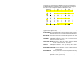
TOP LEVEL MENU OVERVIEW
Top Level
Level 1
EXIT
Function
Exits from Menu
ALARM RESET
Resets any Alarms. Note if Alarm is still
active it will set again. Auto exits menu
RECORD MODE
Enter Password (if set) then press MENU.
OFF
Stop Recording
ON
Start Recording
TRIGGERED
Arm Triggered Recording. An External Event
will start and stop recording as programmed.
NAME FILE
Enter the name for recorded files
up to 8 Characters. Use ▼▲► keys.
◄ key to escape, clear or list directory
Use MENU key to Save and Exit
SAVE CONFIG
Save Configuration
Enter Config File Name - up to 8 Characters.
Use ▼▲► keys.
◄ key to escape, clear or list directory.
Press MENU to save and exit
LOAD CONFIG
Load Configuration.
Enter Config File Name - up to 8 Characters.
Use ▼▲► keys.
◄ key to escape, clear or list directory.
Press MENU to save and exit
Unit will restart on successful load
CURSOR ID
Puts chart in HOLD mode and places cursor on screen.
Use ◄► keys to move cursor and read trend values at top.
Press MENU key to exit this mode.
VIEW FILE
Select an existing file on the CARD to browse.
Enter File Name - up to 8 Characters.
Use ▼▲► keys.
◄ key to escape, clear or list directory.
Press MENU to browse.
CARD
STATUS
Pops up window show memory card status. Includes
capacity, % full, time remaining. Select again to remove
window.
SAMPLE
RATE
Enter Password (if set) then press MENU.
100 S/sec
to
10 sec/S
PASSWORD
ADV. SETUP
DISPLAY ADJ.
Distributed by MicroDAQ.com, Ltd.
Select sample rate from 100 Samples/sec to 10
min/Sample.
Use ▼▲ keys to navigate
◄ key to escape without change.
Use MENU key to select and exit
Enter Password using ▼▲◄► then press MENU
Repeat at prompt, press MENU to select and exit
Enter Password (if set) then press MENU.
See Section 4
Adjust Viewing angle (VIEW) ◄►and
Back Light (BKLT) ▲▼. Press MENU to exit.
24
www.MicroDAQ.com
(603) 746-5524
4.0 ADVANCED SETUP
CHAN A SETUP..
CHAN B SETUP..
ALARMS..
RELAYS..
DISPLAY..
DATA CARD..
CLOCK..
BEEPER..
SAMPLE TRIG..
REC. TRIG..
EXT. INPUT..
4.1
The ADVANCED SETUP menu may be password protected. This
menu is used to program the various operating parameters of the
recorder. This includes analog inputs, alarms, display settings, the
clock and various trigger modes.
All items on this menu have one or more sub-menus. To locate the
Advanced Setup menu, press the MENU button from any normal view
mode. The Advanced Setup menu will not be visible when the menu
first appears. Use the Up Arrow (▲) and Down Arrow (▼) buttons to
scroll and highlight ADV. SETUP and press the MENU button. This
will bring up the Advanced Setup menu shown on the left. Current
settings in sub menus are indicated by a
(check mark) along side
the item or by the item being highlighted.
CHANNEL SETUP
This menu option enables the user to program the inputs of the recorder. Each channel can
be set up as an analog input – volts, currents, thermocouple or RTDs, or as digital inputs
from RPM or frequency measurements. There is no need to swap out modules since the
inputs are universal. Filtering may be applied to each channel for stability of readings or to
catch peak values if the display rate is slower than the sample rate. (The unit always samples
at 100 samples per second per channel. For increased accuracy each range may be
calibrated independently. Use the Up Arrow (▲) and Down Arrow (▼) buttons to scroll and
highlight CHAN n SETUP (n = A or B) and press the MENU button. The menu options are
shown expanded below.
INPUT TYPE
Note: Menu will differ depending on Input Type
selection
VOLTS
250mV
to 25.0Vdc
Select full scale input Voltage
Input is for DC Volts
4-20 mA to
0 - 50mAdc
Select full scale input Current. Input is for DC
milliAmps. External Shunt of 250 Ohms is
required.
J, K, T, E
Select required Thermocouple (T/C) type
Pt385 or 392
Select required RTD Type
100 Hz to 10kHz
Select Frequency for Full Scale Range
100 RPM to
600,000 RPM
Select Speed for Full Scale Range
mA
THERMOCOUPLE
RTDs
FREQUENCY
SPEED
OFF
Turns Channel OFF (toggles)
=OFF
LO SCALE
Default value is low end of range.
For Offset. Use ▼▲► keys to adjust
◄ key escapes, MENU key to Save and Exit
HI SCALE
Default Value is top end of range.
For Full Scale. Use ▼▲► keys to adjust.
◄ key escapes, MENU key to Save and Exit
Distributed by MicroDAQ.com, Ltd.
25
www.MicroDAQ.com
(603) 746-5524
CHAN TAG
Enter a Channel Tag Identifier
up to 5 Characters. Use ▼▲► keys.
◄ to clear or escape.
Use MENU key to Save and Exit
CHAN UNITS
Default value is Range value
Enter a Channel Units. Some Ranges have
defaults. Enter up to 3 Characters. Use ▼▲►
keys. ◄ to clear or escape.
Use MENU key to Save and Exit
FILTER
NORMAL
AVERAGE
HI PEAK
LO PEAK
Note: Unit always samples at 100 samples/sec
internally
No filtering
Display shows AVERAGE over last sample
interval
Display shows HI PEAK (max) values over last
sample interval
Display shows LO PEAK (min) values over last
sample interval
FAST FILT
Averages last 10 samples continuously
CAL ZERO
(If applicable) - Input zero and adjust ▼▲for
zero.
MENU to accept.
CAL SPAN
Input Max Span value and adjust ▼▲for correct
value. MENU to accept.
CAL NOMIN.
Copies default calibration value to this range
CAL. ALL
Copies default value to all ranges
CALIBRATION
4.2
ALARMS
This option is used to program the alarms. There are four alarms and each are programmed
independently. Each alarm may be turned on or off and may be assigned to either channel.
Use the Up Arrow (▲) or Down Arrow (▼) buttons to scroll and highlight ALARMS.. and
press the MENU button. The menu options are shown expanded below.
ALARM n
(n = 1,2,3,4)
ENABLE
Turn Alarm n on or off -
HIGH
LOW
ENABLED is on
Select if ALARM is HIGH
SETPOINT
Set ALARM Trip point. Use ▼▲► keys to adjust
◄ to escape, MENU key to Save and Exit
DEADBAND
Set ALARM DeadBand point. Use ▼▲► keys to adjust
◄ to escape, MENU key to Save and Exit
CHAN A
Select CHAN A as Source for Alarm
CHAN B
Select CHAN B as Source for Alarm
Same as HIGH
HOLD OFF
RESET
DELAY
Distributed by MicroDAQ.com, Ltd.
Select if ALARM is LOW
Use ▼▲ keys to enter time in seconds from Alarm till
relays pull in.
Use ▼▲ keys to enter time in seconds from RESET till
relays drop out.
26
www.MicroDAQ.com
(603) 746-5524
LATCHING
Toggle using MENU - make alarm latching
Prevents a low alarm activating until the setpoint has
been exceeded once
LOCK OUT
DEFAULT
4.3
RELAYS
This option is used to program the physical relay outputs. There are two relays and each is
programmed independently. The relays can be assigned to one or more ALARM events or
the EXTernal INPUT. Use the Up Arrow (▲) or Down Arrow (▼) buttons to scroll and
highlight RELAYS.. and press the MENU button. The menu options are shown below.
RELAY 1
OFF
RELAY is OFF
ALARM 1
RELAY is tied to ALARM 1
ALARM 2
RELAY is tied to ALARM 2
ALARM 3
RELAY is tied to ALARM 3
ALARM 4
RELAY is tied to ALARM 4
EXT INPUT
Relay is tied to EXTernal INPUT
RELAY 2
same as RELAY 1
FAILSAFE
4.4
Relays are energized in the non alarm condition
NEITHER
Select Neither relay as failsafe
RELAY1
Select RELAY 1 as failsafe
RELAY2
Select RELAY 2 as failsafe
BOTH
Select both relays as fail safe
DISPLAY
This option is used to set up the display. The Window Configuration allows the user to
choose how to display data - either as a trend or as digital values or as a combination of both.
The time stamp that appears on the trend can be customized, the menu can be set to
disappear and have the display revert back to normal, and the backlight can be set to go off
after a period of inactivity. (The backlight will restore on any event.) Use the Up Arrow (▲) or
Down Arrow (▼) buttons to scroll and highlight DISPLAY.. and press the MENU button. The
menu options are shown below.
WINDOW CONFIG
TREND
DUAL
DIGITAL
BOTTOM
DIGITAL
INV DIGITAL
Set display to full screen TREND
Set display to DUAL DIGITAL readouts
Set display to TREND in top half, DIGITAL in
lower half (CH B)
Set DIGITAL display to WHITE characters on
DARK background.
ALARM BLINK
DIGITAL value will blink when in alarm
NONE
No imprint of TIME or DATE on TREND display
TIME STAMP
TIME ONLY
TIME imprints on TREND display
TIME & DATE
TIME and DATE imprint on TREND display
Distributed by MicroDAQ.com, Ltd.
27
www.MicroDAQ.com
(603) 746-5524
Set location of Time (& Date) imprint to TOP of
TREND
Set location of Time (& Date) imprint to MIDDLE
of TREND
Set location of Time (& Date) imprint to
BOTTOM of TREND
TOP
MIDDLE
BOTTOM
MENU TIMEOUT
MENU will never Collape (and revert to display
mode)
Choose MENU TIMEOUT from 30 seconds
to 30 Minutes. Menu will revert back to normal
display.
NEVER
30 SEC to
30 MINUTES
BACKLIGHT
LIGHT
TIMEOUT
NEVER
BackLight will never shut off
30 SEC to
30 MINUTES
Choose time to backlight shut off from 30
seconds to 30 Minutes after inactivity.
BATTERY
OFF
Select to turn back light off in battery mode to
save power. (battery is optional)
PEN TYPE
Set CHAN A TREND line dashed instead of
solid
Set CHAN B TREND line dashed instead of
solid
CHAN A - - CHAN B - - -
4.5
DATA CARD
This option contains duplicate menu items to those found in the RECORD MODE menu. In
addition it enables the user to test the card and format it for use (recommended). Use the Up
Arrow (▲) or Down Arrow (▼) buttons to scroll and highlight DATA CARD.. and press the
MENU button. The menu options are shown below.
NAME FILE
Enter the name for recorded files
up to 8 Characters. Use ▼▲► keys.
◄ key to escape
Use MENU key to Save and Exit
SAVE CONFIG
Save Configuration
Enter Config File Name - up to 8 Characters.
Use ▼▲► keys.
◄ key to escape. Press MENU to save and exit
LOAD CONFIG
Load Configuration. Unit will show list of files.
Use ▼▲ to select, ◄ key to escape. MENU to select and load.
Unit will restart on successful load
TEST CARD
This is a non-destructive test to check the card.
FORMAT CARD
This will FORMAT the card for use in the recorder.
ALL DATA WILL BE DESTROYED
Distributed by MicroDAQ.com, Ltd.
28
www.MicroDAQ.com
(603) 746-5524
4.6
CLOCK
This option allows the user to set the time and date and determine what is displayed for time
on the bottom right of the display. Use the Up Arrow (▲) or Down Arrow (▼) buttons to scroll
and highlight CLOCK.. and press the MENU button. The menu options are shown below.
MODES
TIME OF DAY
Select Time Display as Real Time Clock
24 HR
Select Time Display as 24 hour or 12 hour AM/PM
AUTO DST
MM/DD/YY
DD/MM/YY
Select Date format as Day/Month/Year
TIME ZONE
SAMPLE TIME
Show time of actual last sample
DEFAULT
Select default setup: Time of Day, 12 hour format ,
DST on, Date format is MM/DD/YY
Set Time ◄►Adjusts hours. ▲▼adjusts minutes, MENU
accepts
Set Date ◄►Adjust month/year. ▲▼adjusts days. MENU
accepts
SET TIME
SET DATE
4.7
Select to enable Daylight Saving Time adjust
Allow for international time correction. Actual time recorded is
GMT. This corrects for current local time so data is global.
Select date format as Month/Day/Year
BEEPER
This option allows the user to have various events sound the beeper, Alarms, message
boxes and key presses. The tone of the beeper may also be programmed. Use the Up Arrow
(▲) or Down Arrow (▼) buttons to scroll and highlight BEEPER.. and press the MENU
button. The menu options are shown below.
ALARMS
OFF
BEEP on ALARMS turned off if checked
ALARM 1
Beep on Alarm 1
ALARM 2
Beep on Alarm 2
ALARM 3
Beep on Alarm 3
ALARM 4
Beep on Alarm 4
EXT INPUT
ALARM TONE
Beep on External Input
Standard is a continuous high tone
TONE A
Select Alarm TONE A - add warbling effect
TONE B
Select Alarm TONE B - add short silence between tones
TONE C
Select Alarm TONE C - add longer silence between tones
TONE D
Select Alarm TONE D - add long silence between tones
MSG BOXES
BEEP on POP-UP MESSAGE BOXES active if checked
BUTTONS
BEEP on BUTTON PRESS active if checked
Distributed by MicroDAQ.com, Ltd.
29
www.MicroDAQ.com
(603) 746-5524
4.8
SAMPLE TRIGGER
This option allows the user to program what will trigger a change of sample rate in the
displayed or recorded data. Use the Up Arrow (▲) or Down Arrow (▼) buttons to scroll and
highlight SAMPLE TRIG.. and press the MENU button. The menu options are shown below.
Note that if an event is selected to change the sample rate, when exiting the menu the
sample rate menu will be displayed. Use the Up Arrow (▲) or Down Arrow (▼)
buttons to scroll and highlight the new sample speed and press the MENU button to
select and the Left Arrow (◄) button to exit.
4.9
OFF
No Sample Rate change if checked
ALARM 1
Sample Rate change on Alarm 1
ALARM 2
Sample Rate change on Alarm 2
ALARM 3
Sample Rate change on Alarm 3
ALARM 4
Sample Rate change on Alarm 4
EXT INPUT
Sample Rate change on External Input
RECORD TRIGGER
This option allows the user to choose an event to start the recording. Use the Up Arrow (▲)
or Down Arrow (▼) buttons to scroll and highlight REC. TRIG.. and press the MENU button.
Select either OFF, ALARM 1 through 4 or EXTERNAL INPUT as the record trigger.
Note that if an alarm reset delay is set (see Section 4.2), the unit will continue to
record for this time period AFTER the alarm has gone away.
4.10 EXTERNAL INPUT
This option allows the user to program the external digital input. This needs to be
programmed before it can be used for event triggering if programmed above. Use the Up
Arrow (▲) or Down Arrow (▼) buttons to scroll and highlight EXT. INPUT.. and press the
MENU button. The menu options are shown below.
ENABLE
Enable External Input
HIGH
External Sense is HIGH to register
LOW
External Sense is LOW to register
HOLD OFF
Time in seconds from EXT input present till recognized
RESET DELAY
Time in seconds from EXT input absent till recognized
LATCHING
Once set, will remain set till the RESET option is pressed
LOCK OUT
External Input requires a change of state in order to be recognized.
For a High condition on startup or reset, if the input is high at that time
it needs to go low first, then high in order to be recognized.
DEFAULT
Set Defaults - Disabled, High level, all else set to zero
Distributed by MicroDAQ.com, Ltd.
30
www.MicroDAQ.com
(603) 746-5524
5.0 MISCELLANEOUS
5.1
CALIBRATION
Before leaving the factory, the recorder is calibrated using NIST traceable sources. The
calibration values are stored in non-volatile memory. The unit is calibrated to meet
specification but the user may wish to re-calibrate the unit, or calibrate specific input ranges
for increased accuracy.
Calibration is the process of “fine tuning” each input for various differences that may arise
due to manufacturing processes, gain errors, temperature offsets and other physical
parameters. Real analog to digital (A/D) converter values are corrected by first adding an
offset correction value, nominally zero, to the reading to correct for offsets from zero, and
then multiplying it by a span correction value that's nominally 1 to correct for gain errors.
Calibration setup can be found in the Channel x Setup Menu (x = A or B) under the
ADVANCED SETUP menu options. Each channel needs to be calibrated independently.
There are four options on the calibration menu:
OFFSET
adjusts the offset correction above or below actual 0 (zero), in steps
equal to the resolution of the A/D converter itself.
SPAN
adjust a span correction value above or below actual 1, also in small
amounts.
NOMINAL
depending on the input range selected, either resets the correction
values to 0 and 1, or copies those values from the range it's a derived
from. This usually affects only the input type category selected for the
current channel.
NOMINAL ALL will reset all correction values for all input types on both channels when
selected from any input type and channel, a sort of master reset. This is
the default in the event that calibration data is found to be corrupted in
the non-volatile memory.
5.1.1
BASIC CALIBRATION
All calibration values are derived from a couple of key calibration points. Thereafter, any
fine tuning done to a specific input on a channel is saved for that channel and input range
only. The key calibration constants are for:
Lo Volts
covering the 250mV, 1.25V, 2.50V ranges and should be done
on the 250mV range – each channel
Hi Volts
covering the 5.00V, 12.5V, 25.0V ranges and should be done
on the 5.00V range – each channel
THERMOCOUPLES
which are derived from the Lo Volts calibration value require
an additional offset to compensate for the ambient temperature
sensor – each channel
RTDs
which are derived from Lo Volts calibration value require an
additional span calibration to correct for the internal current
source – each channel
Distributed by MicroDAQ.com, Ltd.
31
www.MicroDAQ.com
(603) 746-5524
CURRENTS
which are derived from the Hi Volts calibration value require an
additional span calibration to correct for the external resistor
(Customer supplied) – each channel
FREQ and SPEED
requires only a time base calibration shared for both channels
In general, to calibrate an analog input, first set the specific channel to an input type in the
ADVANCED SETUP MENU - CHANNEL SETUP - INPUT TYPE (see Section 4.1). Once
an input type has been chosen, select CALIBRATION (see Section 4.1). Do not change
the units from the default values set when that range is selected (i.e. leave volts as volts
and current as current).
Apply a "zero" value to the input and using the up (▲) and down (▼) arrow buttons adjust
the OFFSET until the onscreen indications shows zero.
Apply a "high" value to the same input and using the up (▲) and down (▼) arrow buttons
adjust the SPAN until the onscreen indication agrees with the input (Note – use an input
value slightly less than the full scale value to prevent an overrange indication).
Repeat for all input types and channels to be used, if not all of them.
5.1.2
EXAMPLES
Volts: Should be done for the Lo Volts - 250mV, 1.25V, 2.50V ranges, and Hi Volts 5.00V, 12.5V, 25.0V ranges using the 250mV and 5.00 volt ranges respectively. For each
channel individually, set the input for 250mV and go to Calibration. Short the input and
adjust the OFFSET until 0 is indicated. Then apply a near full scale input (so as to not
over range the input, say 240 mV on the 250 mV range) and adjust the SPAN.
Thermocouples: (preferred method) First calibrate lo VOLTS range (250mV) for the
same channel as described above. Then switch to Thermocouple range. Select
NOMINAL to copy the volts calibration to thermocouple range. The recorder is now
calibrated for ideal sensors. Refine the calibration by either shorting the input (you need
to know the ambient temperature) or attaching a thermocouple sensor or calibrator of the
correct type for the selected range, and then if necessary, adjust the OFFSET until the
correct temperature is displayed – this corrects the ambient temperature sensor. If there's
a known "high" temperature source handy use that to fine tune the SPAN value.
Currents: (preferred method) First calibrate Hi VOLTS range (5.00V) for the same
channel as described above. Then switch to any CURRENT range. Select NOMINAL to
copy the volts calibration to the current range. The recorder is now calibrated for ideal
resistor (250 ohm). Refine calibration for resistor and sensor current tolerances by
attaching a 250 ohm +0.1% resistor and input sensor matching the selected range. Apply
low value inputs to adjust the OFFSET value, and high value inputs to adjust the SPAN
value.
RTDs: (preferred method) First calibrate lo VOLTS range (250mV) for the same channel
as described above. Then switch to RTD range. Select NOMINAL to copy the volts
calibration to RTD range. The recorder is now calibrated for ideal sensors and internal
current source. Refine the calibration by applying an accurately known resistance for a
given temperature (you may need resistance to RTD tables). Adjust the SPAN until the
correct temperature is displayed – this corrects for the internal current source.
Frequency (RPM or Hz): Apply a calibrated frequency input near the high end of the
selected input range of either channel. Adjust SPAN until the indicated value is correct.
There is no applicable OFFSET adjustment to be made.
Distributed by MicroDAQ.com, Ltd.
32
www.MicroDAQ.com
(603) 746-5524
Recommended procedure for full initial calibration, in this order:
- Calibrate 250 mV range, both channels using a calibrated source.
- Calibrate 5.00 V range, both channels using a calibrated source
- Calibrate any T/C range, both channels using the NOMINAL method.
- Calibrate any RTD range, both channels using NOMINAL method
- Calibrate any current range, both channels using NOMINAL method
- Calibrate any Tach range, either channel using a calibrated signal source.
NOTES:
As with other numeric editing, the rate that a calibration value is adjusted accelerates with
the length of time the button is pressed.
Calibrating either channel for tachometry calibrates both channels and does not have to
be repeated for each channel as they use the same base counter. Additionally there's no
OFFSET adjustment for these inputs.
Thermocouple and RTD linearization tables are very accurate; usually calibrating the
250mV range for the same channel and then copying the calibration values using
NOMINAL should be enough. Remaining sources of error are the ambient sensor
(probably small) for the thermocouple and the current source (small) for the RTD, and the
actual sensors themselves. The ambient sensor can be calibrated by adjusting the
OFFSET with the thermocouple at some known temperature (such as ice water) or a
known room temperature with a wire short on the input. The input sensor span
adjustment would need a high temperature point to calibrate.
There can be interaction between the OFFSET and SPAN with the thermocouple input
since it can't be easily determined when exactly 0 volts is applied in combination from the
ambient and input sensors. This can happen with other input types where the input used
for the OFFSET adjustment does not present 0 volts to the input.
Calibration values are copied to an EEPROM (non volatile) device when performing the
calibration operations. These values are copied from the EEPROM upon every power up
of the recorder and tested for corruption. If the values are found in error then nominal
values are inserted in all categories.
Distributed by MicroDAQ.com, Ltd.
33
www.MicroDAQ.com
(603) 746-5524
5.2
SPECIFICATIONS
Input Power:
Recorder: 9Vdc +0.5V @ 5VA (depends on external loads)
External AC Universal adaptor: 100 – 240Vac 50/60 Hz
Optional isolated: 12 – 24 Vdc input (not compatible with battery
backup option)
Battery Option:
Internal battery pack provides uninterrupted operation during black
out. 6Vdc 2400 mAH NiMH – backup time 6 hours typical –
depends on external load.
Output:
2 outputs 5Vdc @ 50mA to power external sensors
Isolation – 300V DC/AC to system ground/chassis.
No of Channels:
2
Universal DC Input:
Isolated input: 300V AC/DC to system ground/chassis. Inputs share
a common ground connection.
DC Input:
Resolution: 0.025%
Voltage:
Ranges: 0 to 250mV; 1.25V; 2.5V; 5V; 2.5V; 25V
Accuracy 0.1%.
Current:
Accuracy: 0.1% excluding 250 ohm external shunt (required)
Ranges: 0 – 20mA; 4 – 20mA; 0 – 50mA; 10 – 50mA
Thermocouple:
Accuracy: 0.3%. Ambient temp. sensor accuracy +1.5°
J
K
T
E
-100 to 760 °C +2°C
-100 to 1000°C +2°C
-100 to 400 °C +2°C
-80 to 400 °C +2°C
(-148 to 1400 °F +3°F)
(-148 to 1830 °F +3°F)
(-148 to 750 °F +3°F)
(-112 to 750 °F +3°F)
RTD:
2 or 3 wire. Resolution 0.1°C, Accuracy 0.3%
Internal current source: 1mA
100 ohm Pt385
-100 to 750°C (-148 to 1380 °F)
100 ohm Pt 392
-100 to 750°C (-148 to 1380 °F)
Frequency Input (Hz)/
Speed Input (RPM):
Range:
Accuracy:
Input Impedance:
Measurement Rate:
Math Function:
>100k
up to 100 samples/sec per channel
y = mx + b; average, hi peak., lo peak
0 – 10,000 Hz or 0 – 600,000 RPM
Freq: +1Hz;
RPM: +1 RPM to 9,999 RPM then +10RPM
Input:
low: <1.0Vdc high: >3.0Vdc <12Vdc
Pulse width: 10чsec minimum
Media:
Display:
Compact Flash to 2 GB.
LCD Graphics 160 x 80 pixels black FSTN with White LED backlight
User controlled Backlight level and Contrast adjust (electronic)
Display Modes:
Trending (Horizontal), Large Dual Digital Readout, Mixed Mode
nd
User Interface:
5 buttons keypad with 2 Function operation
Clock:
Internal battery backed clock, with auto leap year and daylight savings
Relay Output:
Two alarm outputs: 30V 0.5A Form A relays
Opto-isolated Input: One input 5 to 12Vdc operation @ 10mA typical.
Audible:
Internal buzzer (tones)
Distributed by MicroDAQ.com, Ltd.
34
www.MicroDAQ.com
(603) 746-5524
Dimensions:
Front panel 96mm x 96mm (1/4 DIN) x 152mm (3.78 x 3.78 x 6
inches).
Environmental:
Indoor Use Only
Installation Category II per IEC 664
Pollution Degree Level II per IEC61010-1
Altitude up to 2,000 m
Temperature -10 °C to 50 °C operating per IEC61010-1
Humidity Maximum relative humidity 80% for temperatures up to 31
°C decreasing linearly to 50% relative humidity at 40 °C.
Certification:
CE – EN61326 EMI/EMC
UL and cUL
EN61010-1 Safety
Optional Communications
USB
Front panel USB 2.0 slave port for data transfer and configuration.
Ethernet
10/100 Ethernet
Distributed by MicroDAQ.com, Ltd.
35
www.MicroDAQ.com
(603) 746-5524
APPENDIX A - UNITS LABEL CHARACTERS
The following is a list of the characters are available any place text can be entered. The list
will start with the A character (underlined) and the UP and DOWN arrows move through the
list in order left to right. The characters in shadow are NOT legal for file names.
(space)
.(
0
8
.@ .
H
P
X
.`.
h
p
x
.↑
!
)
1
9
A
I
Q
Y
a
i
q
y
↓
"
*
2
.:
B
J
R
Z
b
j
r
z
®
#
+
3
;
C
K
S
..[
c
k
s
.{
¬
$
,
4
<
D
L
T
\
d
l
t
|
°
%
5
=
E
M
U
]
e
m
u
}
µ
&
.
6
>
F
N
V
^.
f
n
v
~
Ω.
'..
/..
7
?.
G
O
W
_
g
o
w
#.
APPENDIX B - ERROR AND INFORMATION MESSAGES
The following messages appear on the Graphics screen as a result of the following:
(suggested solutions appear in italics)
ACCESS DENIED An incorrect password was entered while attempting to gain access to a
password protected function. Find someone who has the right password.
BAD FILENAME
The filename entered does not meet the DOS requirement. Use A to Z
and 0 to 9 without spaces, 8 charactres max. Re-enter the name.
CARD ABSENT
Failed attempt to read from (viewing) or write to (recording) a memory
card which is not present. Insert a card.
CARD ACCESS ERROR Failed attempt to read or write a memory card due to file data
corruption. Format and erase card - data will be lost.
CARD FULL
Failed attempt to write to a memory card which is filled to capacity.
Exchange card with a new one that has spare capacity.
ENTER CURRENT PASSWORD You have attempted to access a password protected
function and must enter the password to continue. Enter
current password.
ENTRIES MISMATCH
ENTRY ERROR
This time password did not match last time password when setting
up. Try it again, only more slowly.
An illegal number of keystrokes was entered while entering the
password. Try it again, only more slowly.
Distributed by MicroDAQ.com, Ltd.
36
www.MicroDAQ.com
(603) 746-5524
FILE NOT FOUND Failed attempt to read a data file or configuration file due to the fact that
no such file exists on the memory card. Get the correct card.
FORMAT CARD
Card is incompatible or unformatted. Requires formatting.
OVERWRITE CONFIG. FILE? A config file already exists on the memory card. Writing to the
card will overwrite this existing file. The unit is checking user
intent. Press the UP ARROW key to overwrite the existing
file, any other key to exit.
STOP RECORDING FIRST
TEST FAIL
The function you are trying to perform cannot be done while
the unit is in record mode. Stop recording and try again.
The card has errors on it and did not pass the card test. Try reformatting
the card or swap the card.
APPENDIX C - MASTER RESET
The master reset is used to restore all factory defaults to the unit. It is used in the unlikely
event of the unit losing or corrupting the contents of its nonvolatile memory. All user
configurations will be lost.
To reset the unit to the factory defaults, hold the two outer keypad buttons down
simultaneously (The DOWN and LEFT arrows) while powering up the unit. Wait two to three
seconds and then release.
APPENDIX D – RE-PROGRAMMING FIRMWARE
The operating firmware in the unit is programmed into flash memory and can be updated in
the field. It is loaded from the compact flash card. User’s can upgrade their firmware by
simply downloading the latest firmware from the Monarch Instrument website,
http://www.MonarchInstrument.com/DC1250, saving it onto the CompactFlash™ card,
inserting the CompactFlash™ card into the unit and following the steps below.
The operating system is in a file called DC1250.hex. Once this file is on the CompactFlash™
card, insert the card into the unit and turn the power off. Press and hold the MENU button
and Left Arrow (◄) simultaneously and power the unit back on.
The POWER LED will come on fully bright; the other will blink as the card is accessed. If the
program is loaded successfully, the two LEDs will alternate. If the load failed, the two LEDs
will blink in unison. It takes 10 to 15 seconds to load the program. If the load should fail, try it
again. If it still fails, reload the file on the card.
Remove the power and re-apply it. The screen will show the latest firmware revision and build
date.
Distributed by MicroDAQ.com, Ltd.
37
www.MicroDAQ.com
(603) 746-5524