1
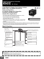
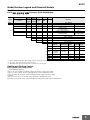
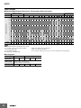
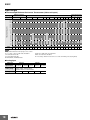
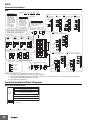
E5EC
Alarm type
Each alarm can be independently set to one of the following 19 alarm types. The default is 2: Upper limit. (see note.)
Auxiliary outputs are allocated for alarms. ON delays and OFF delays (0 to 999 s) can also be specified.
Note: In the default settings for models with HB or HS alarms, alarm 1 is set to a heater alarm (HA) and the Alarm Type 1 parameter is not displayed.
To use alarm 1, set the output assignment to alarm 1.
Set
value
Alarm output operation
When alarm value When alarm value
X is positive
X is negative
Output OFF
Alarm type
0
Alarm function OFF
1
Upper- and lower-limit *1
2
Upper- and lower-limit
range *1
4
6
7
8
9
11
Absolute-value upper-limit
ON
OFF
Absolute-value upper-limit
with standby sequence
ON
OFF
Absolute-value lower-limit
with standby sequence
ON
OFF
LBA (alarm 1 type only)
PV change rate alarm
14
SP absolute value
upper limit
ON
OFF
SP absolute value
lower limit
ON
OFF
MV absolute value
upper limit *9
ON
OFF
MV absolute value
lower limit *9
ON
OFF
RSP absolute value
upper limit *10
ON
OFF
RSP absolute value
lower limit *10
ON
OFF
16
17
18
19
L
ON
OFF
PV
ON
OFF
L
PV
*3
PV
*4
X
SP
PV
ON
OFF
PV
ON
OFF
PV
ON
OFF
PV
ON
OFF
PV
ON
OFF
PV
ON
OFF
X
SP
X
0
X
0
X
0
X
0
H SP
H<0, L>0
|H| < |L|
X
0
SP
ON
OFF
SP
ON
OFF
MV
ON
OFF
MV
ON
OFF
RSP
ON
OFF
RSP
ON
OFF
X
0
X
0
X
0
X
0
X
0
Case 3 (Always ON)
H
SP L H
H>0, L<0
|H| > |L|
H
SP
L
H<0, L>0
|H| ≥ |L|
L SP
SP H
L
H>0, L<0
|H| ≤ |L|
*3. Set value: 4, Upper- and lower-limit range
Case 1
Case 3 (Always OFF)
Case 2
H<0, L<0
L
H SP
H<0, L>0
|H| < |L|
SP L
H
H
H>0, L<0
|H| > |L|
PV
SP
H
SP
L
L SP
SP H L
No alarm
Set the deviation in the set point by setting the alarm upper
limit (H) and alarm lower limit (L). The alarm is ON when the
PV is outside this deviation range.
Set the upward deviation in the set point by setting the alarm
value (X). The alarm is ON when the PV is higher than the SP
by the deviation or more.
Set the downward deviation in the set point by setting the
alarm value (X). The alarm is ON when the PV is lower than
the SP by the deviation or more.
Set the deviation in the set point by setting the alarm upper
limit (H) and alarm lower limit (L).
The alarm is ON when the PV is inside this deviation range.
A standby sequence is added to the upper- and lower-limit
alarm (1).*6
X
SP
PV
A standby sequence is added to the upper-limit alarm (2). *6
PV
A standby sequence is added to the lower-limit alarm (3).*6
X
SP
X
0
PV
X
0
PV
X
0
PV
X
0
PV
The alarm will turn ON if the process value is larger than the
alarm value (X) regardless of the set point.
The alarm will turn ON if the process value is smaller than the
alarm value (X) regardless of the set point.
A standby sequence is added to the absolute-value upperlimit alarm (8). *6
A standby sequence is added to the absolute-value lower-limit
alarm (9). *6
*7
*8
H<0, L<0
L
X
-
With set values 1, 4 and 5, the upper and lower limit values can be set
ndependently for each alarm type, and are expressed as “L” and “H.”
*2. Set value: 1, Upper- and lower-limit alarm
Case 2
PV
SP
H
SP
*1
Case 1
X
H
SP
ON
OFF
12
13
15
SP
ON
OFF
ON
OFF
PV
X
ON
OFF
Lower-limit with standby
sequence
Absolute-value lower-limit
10
X
ON
OFF
Upper- and lower-limit with
standby sequence *1
*5
Upper-limit with standby
sequence
5
*2
PV
SP
ON
OFF
Lower-limit
H
SP
ON
OFF
Upper-limit
3
L
ON
OFF
Description of function
H<0, L>0
|H| ≥ |L|
H>0, L<0
|H| ≤ |L|
X
0
SP
X
0
SP
X
0
MV
X
0
MV
X
0
RSP
X
0
RSP
This alarm type turns ON the alarm when the set point (SP) is
higher than the alarm value (X).
This alarm type turns ON the alarm when the set point (SP) is
smaller than the alarm value (X).
This alarm type turns ON the alarm when the manipulated
variable (MV) is higher than the alarm value (X).
This alarm type turns ON the alarm when the manipulated
variable (MV) is smaller than the alarm value (X).
The alarm will turn ON when the remote SP (RSP) is larger
than the alarm value (X).
The alarm will turn ON when the remote SP (RSP) is smaller
than the alarm value (X).
*4. Set value: 5, Upper- and lower-limit with standby sequence
For Upper- and Lower-Limit Alarm Described Above *2
• Case 1 and 2
Always OFF when the upper-limit and lower-limit hysteresis overlaps.
• Case 3: Always OFF
*5. Set value: 5, Upper- and lower-limit with standby sequence
Always OFF when the upper-limit and lower-limit hysteresis overlaps.
*6. Refer to the E5CC/E5EC Digital Controllers User's Manual (Cat. No. H174)
for information on the operation of the standby sequence.
*7. Refer to the E5CC/E5EC Digital Controllers User's Manual (Cat. No. H174)
for information on the PV change rate alarm.
*8. Refer to the E5CC/E5EC Digital Controllers User's Manual (Cat. No. H174)
for information on the PV change rate alarm.
*9. When heating/cooling control is performed, the MV absolute upper limit
alarm functions only for the heating operation and the MV absolute lower
limit alarm functions only for the cooling operation.
*10. This value is displayed only when a remote SP input is used. It functions in
both Local SP Mode and Remote SP Mode.
19