
1
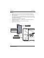
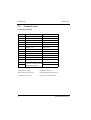
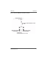
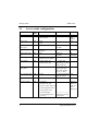
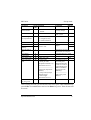
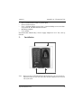
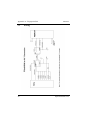
PRX-40/A
Proximity Reader
Product Manual
Synel Industries Ltd.
Manual was issued on 3/6/05.
Catalog no. 652745, Document no. PRX40A-222-02
Copyright © 2004-2005 Synel Industries Ltd. All rights reserved.
This document has been prepared for controller firmware version 2.00 of the
PRX40A proximity reader. Reproduction or use, without express permission
of editorial or pictorial content, in any manner is prohibited. No patent liability is assumed with respect to the use of the information contained herein.
While every precaution has been taken in the preparation of this manual,
Synel Industries Ltd. assumes no responsibility for errors or omissions. Neither is any liability assumed for damages resulting from the use of the information contained here-in.
SY is a trademark of Synel Industries Ltd.
All trade names referenced herein are either trademarks or registered trademarks of their respective companies.
Synel Industries Ltd.
PRX-40/A
1.
Introduction
Introduction
The PRX-40/A proximity reader access unit is one of the compact access
control - unit series manufactured by Synel. The card must be placed at a distance of about 10 cm from the device.
This reader can work as a stand-alone reader, or with a master controller connected to upto 16 reader units.
It was developed as a compact, easy-to-use proximity terminal, granting
access to secure areas. The PRX-40/A works with various unit settings,
according to a predefined security level. This device is made of strong ABS
plastic.
Defining parameters in PRX-40/A is simple while maximum security is
enabled by using the set-up 8 digit code (the default number is 12345678)
greatly improving security.
In stand alone mode PRX-40/A grants secure access for approximately 285
card holders, stored in an authorized list within the terminal. This list is created and edited on the unit’s compact keyboard, eliminating the need of connecting to a computer.
When working in online mode (as of Master version 3.20), the PRX40A unit
uploads employee data from Master to its own memory and relay on this data
when allowing/rejecting an employee if the connection with Master is lost.
PRX40A can manage unauthorized (black list) or authorized (white list)
employee lists for access control purposes.
1.1
PRX-40/A Apparatus
The proximity reader access unit may be mounted on a wall. The enclosures
include a PC board assembly.
Over and above operating as an access terminal, the PRX-40/A terminal has
additional circuitry for storing card-holder data. Operating power for the unit
is obtained from a wall adapter.
Synel Industries Ltd.
1
Installation
2.
Installation
2.1
General
PRX-40/A
The PRX-40/A proximity unit can be installed in any building. The back
panel of the unit serves as an installation template. Mounting screws and
anchors are also provided. Follow the guidelines below:
•
The installation location selected should be as far away as possible from
electrical power source reference such as power equipment, computers,
motors, pumps, etc.
•
If you are installing more than one Synel proximity reader, make sure the
readers are installed at a distance of at least 50 cm from one another (a
distance longer 5 times their reading limit).
•
Near metal objects reading range may decrease.
•
Use a linear power supplier and not a switching power supplier. A
switching power supplier auto-generates an electro-magnetic field that
shortens the reading range It is advisable to connect an independant
power supplier to the reader.
•
Make sure that the reader is not in a metalic materials surroundings.
When mounting on a gypsum wall, make sure that there is no rear metalic reinforcement. If the reader is mounted on a concrete wall the reader
must be mounted up to 20 cm from the wall.
•
It is recommended that when swiping the badge it will face the reader.
Thus, the badge will receive maximal energy.
•
Use a power adaptor dedicated to the proximity reader access unit. Make
sure the adapter carries a safety recognition marking: UL, CSA or CE.
2.2
Mounting
Option A
1.
2.
3.
6.
7.
Remove screw covers and screws from top and bottom of the unit.
Open the back of the unit.
Drill both fastening holes at either end and one hole towards the center
for the cable.
Fasten the back of the unit to the wall.
Connect the cable wires via middle hole or bottom hole option (see
diagram).
Close the unit.
Replace the screw covers.
2
Synel Industries Ltd.
4.
5.
PRX-40/A
Installation
Option B
1.
2.
3.
4.
5.
6.
7.
Remove screw covers and screws from top and bottom of the unit.
Hold the unit against the wall and mark the drilling location through
the screw holes.
If the cable wires use the middle hole option, remove the back panel
and use it to mark the position of the cable hole (center of panel). Drill
the cable hole in the wall.
Drill the two fastening holes in the wall.
Connect the cable wires via middle hole or bottom hole option (see
diagram) as required.
Fastened the unit to the wall with screws provided.
Replace the screw covers.
PRX-40
A. Open screw covers
and screws.
B. Remove Back Panel
Location of screws for
option “B” fastening.
Option “B”
C. Drill holes
Center hole
ti
Option “A”
PRX-40 Back
P l
Bottom hole option
Synel Industries Ltd.
3
Installation
2.3
PRX-40/A
Connect wires
Connector J5/14 pin
Wire No. Wire Function
Present Color Code
1
Vin Power (Power Input) Red
2
Gnd
Black
3
- TxRx RS-485
Grey
4
+ TxRx RS-485
Purple
5
TxD RS -232
White
6
RxD RS -232
Dark Green
7
Alarm
Brown
8
Relay common (C)
Blue
9
Normally Closed (N.C)
Yellow
10
Normally Open (N.O.)
Orange
11
Bell (1)
Pink
12
Bell (2)
Light green
13
Sensor input: Dry contact Light Blue
or AC/DC. Sensing regard Brown/White
jumper JP23 settings
14
Connector J4 (9 pin)
Keyboard connector
ISP Connector J12 (6 pin)
(programming the CPU slave)
Connector J13 (14 pin)
Option for external reader
4
Synel Industries Ltd.
PRX-40/A
Installation
How to connect the PRX40A to the Master controller:
Synel Industries Ltd.
5
Installation
2.4
PRX-40/A
Jumpers
Jumper
JP2 (SMD)
JP3 (SMD)
JP4 (SMD)
JP7 (SMD)
JP10 (TH)
Function
JP2 closed and JP3 open = Linear decoding
JP2 open and JP3 closed = Synel decoding
Default
Linear
Cross point decoding (currently NA)
Connect RS-485 termination resistor
W.D. Reset for the master CPU- [1-2] Closed
Programming of the master CPU - [2-3] Closed
JP11(TH)
PSEN (Programming) - must be closed when programming the master CPU.
JP12 (SMD) Tamper switch enabled [1-2] closed
Tamper switch disabled [2-3] closed
JP20 (T.H)
Closed- Stand alone
Open- Online with Master
JP21 (T.H)
Contacts switching protection in DC- closed
Contacts switching protection in AC- open
JP22 (SMD) Connecting clock to slave CPU
JP23 (T.H)
Select sensor option:
[1-2] and [3-4] Closed - dry contact
[2-3] Closed - AC/DC
JP24 (T.H)
Reset for the slave/reader CPU- [2-3] closed
Programming of the slave/reader CPU [1-2] Closed
6
Open
[1-2] closed
Open
[2-3] closed
Closed
Closed
[2-3] closed
[1-2] and [3-4]
closed
[2-3] closed
Synel Industries Ltd.
PRX-40/A
3.
Set-up mode
Set-up mode
PRX-40/A programming can be divided to three categories:
1.
Access Cards configuration (authorized personnel)
2.
General definitions
3.
Indicator definitions
All definitions of Management modes are listed in the table below.
The codes in the table below can be used only after completing set-up mode
as follows:
Step 1:
Press 3 times simultaneously on function keys 1 & 2 (each time
will be followed by a short beep and an orange led will be lit).
Step 2:
Input
Indicator signalling
1st 1&2
Short beep+2nd red led ON
2nd 1&2
Long beep+2nd red led ON
3rd 1&2
2 long beeps+2nd green led flashes
Enter the 8 digit master code (the default number is 12345678).
Then insert the relevant set-up code (see next page).
Synel Industries Ltd.
7
Set-up mode
3.1
PRX-40/A
Access cards configuration
Parameter
Sensor mode
Set-up Function
Code
30 0 Door open request
1 Door Sensor
Sensor type
31
Sensor door active
time (open)
Toggle relay mode
32
Toggle relay timeout
Card list type
34
Alarm mode
51
Alarm pulse activating time
52
0000-9999
Door opening time
10
000-255
Communication
ID
Operation mode
14
1-16
12
0
1
2
3
4
5
6
8
33
35
0 N.O
1 N.C
000-255
0- Disable
1 - Enable
00-99
1- Black list (Rejected)
0- White list (Accepted)
0 Latch (led is on)
1 Pulse (led is off)
Comments
Default
Door
open
request
N.C
Define in
seconds
In minutes
15 sec.
Define in
seconds
00Disabled
0
Disable
1 = Led is off
depending on pulse
time (code 52)
You must always
0 sec.
key-in time in a
four digit format:
10 sec. = 0010
In 1/10 seconds step 3 sec.
(0 to 25.5 sec.)
Defines terminal ID 01
Card only
Global code only
Card or code (card no.)
Card and global code
Card and pin code
Card and finger
----------------------Code and finger (fin- Functions 5-6 only
ger only)
with PrintX
There is a
different
code for
each
employee
Synel Industries Ltd.
PRX-40/A
Set-up mode
Parameter
Set-up Function
Code
Duress code
50 0 Disable
enable/disable
1 Enable
Define duress code 53 0000-9999
Card reading/
check parameters
11
New master code
Erase all cards
Initialisation of
memory
Vocal ID indication
13
60
61
Reset alarm
Control door
New global code
Insert card using
card
4
0
15
20
Delete card from
list using card
21
1,2- Offset (01-37)
3,4- Length (01-06)
5,6- Total Characters
00000000-99999999
Master Code
7
Comments
Default
Activating alarm
and relay output
Active in operation
mode 1,2,3,4
01
16
00
8 digit code
Type master code 8 digits
Long buzzer for tens
Short buzzer for uniques
When the alarm is in latch
4 digit new code
1. Swipe card
2. Insert pin code
(If Operation Mode is 4)
Terminal reverts to 1.
---------------------------Fingerprint (OperationMode 5):
1. Swipe card (2 beeps
confirm swipe).
2. Place finger
Terminal reverts to 1.
Card
9999
According to operation mode press
7&8 simultaneously
in order to revert to
normal mode (press
Enter in terminals
that consist of an
Enter key).
----------------------Mode 5 only with
PRintX *
* Note:
After swiping all cards, you should wait time-out or press 7&8 simultaneously
(press Enter in terminals that consist of an Enter key) once. Then all data will
be saved!
Synel Industries Ltd.
9
Set-up mode
Parameter
Insert card using
keyboard
Delete card using
keyboard
Insert card by
Index
Delete card by
index
PRX-40/A
Set-up Function
Code
22 1. Key-in card
2. Insert pin code
(In Operation Mode-12
press key no. 4)
Terminal revert to 1.
----------------------------Fingerprint (In Operation
Mode-12 press key no. 6):
1. Key-in code (depends
on card length).
2. Place finger
Terminal reverts to 1.
23 Card number
24
25
1. Card index 4 digits
from 0000-0300
2 . Swipe card
In Operation Mode-12
press key no. 4:
3. Insert pin code
Card index - 4 digits
Comments
Default
According to operation mode press
7&8 simultaneously
in order to revert to
normal mode.
(press Enter in terminals that consist
of an Enter key)
----------------------Mode 6 only with
PRintX
Highest possible
index depends on
card length (code
11)
Time Out
After every entry a LED is lit (while waiting for the next entry). After the
LED goes out the unit exits the “Programming Mode” and resets (action must
be repeated from the beginning).
3.1.1.
Management of Access Cards (authorized personnel)
Managing access Cards can be performed three ways:
Using Keyboard - Keying-in the keyboard the card number
Using Card - Swiping the card
By Index - Enables deleting an employee without a card
10
Synel Industries Ltd.
PRX-40/A
Set-up mode
Using Keyboard
Build list:
After entering set-up mode key-in code 22 (key-in card number to list) (Up to
13 characters in Linear decoding) and key-in all relevant cards. After each
keyed-in card number 2 short beeps will indicate that the number was registered successfully. After keying-in all card numbers press 7&8 simultaneously (mandatory) (press Enter in terminals that consist of an Enter key)
in order to revert to normal mode.
Note: In operation mode 4 - card and pin code, the user must key-in the
card number and then key-in the pin code for each card (4 digit code).
Delete list:
After entering set-up mode key-in code 23 (Delete card by keyboard) and
key-in all irrelevant cards. After each keyed-in card number 2 short beeps
will indicate that the number was deleted successfully. After keying-in all
card numbers press 7&8 simultaneously (mandatory) (press Enter in terminals that consist of an Enter key) in order to revert to normal mode.
Using Card
Build list:
After entering set-up mode key-in code 20 (Insert card to list by card) and
swipe all relevant cards. After each swiped card 2 short beeps will indicate
that the number was registered successfully. After swiping all cards press
7&8 simultaneously (mandatory) (press Enter in terminals that consist of an
Enter key) in order to revert to normal mode.
Note: In set-up code 12: operation mode no. 4 - card and pin code, the user
must swipe the card and then key-in the code (a 4 digit code).
Delete list:
After entering set-up mode key-in code 21 (delete card by card) and swipe all
irrelevant cards. After each swiped card 2 short beeps will indicate that the
number was deleted successfully. After swiping all cards press 7&8 simultaneously (mandatory) (press Enter in terminals that consist of an Enter key)
in order to revert to normal mode.
Note: Whenever a task is completed successfully, a LED flashes and the
buzzer beeps.
By index
Insert cards:
Synel Industries Ltd.
11
Set-up mode
PRX-40/A
After entering set-up mode, key-in code 24 (Insert card by Index) and key-in
a 4 digit index, swipe card. 2 short beeps will indicate that the number was
registered successfully. After swiping all cards press 7&8 simultaneously
(mandatory) (press Enter in terminals that consist of an Enter key) in order
to revert to normal mode.
Delete cards:
After entering set-up mode key-in code 25 (delete card by index) and key-in a
4 digit index. 2 short beeps will indicate that the index was deleted successfully. After swiping all cards press 7&8 simultaneously (mandatory) (press
Enter in terminals that consist of an Enter key) in order to revert to normal
mode.
Terminology
Card Only - Control is performed by Card only.
Global Code only - common global code (4 digit code – used by all cardholders).
Card or code - Control is performed by Card or keying-in number of card (the
length of the keyed-in number must be identical to the defined card length).
Card and Global Code - Control is performed by Card and a common global
code (four digit code – used by all card-holders).
Card and PIN Code – Control is performed by Card and a personal four digit
code. This mode is the most secure.(4 digit code – used by each card-holder).
3.2
General definitions
Open Door
Access can be given by using a Master Code. After entering “Programming
Mode,” enter “0”.
Open Door Time
It is possible to adjust the “window” of accessability during which a door
opens when accessed. To change the accessability time, after entering the
“Programming Mode,” enter “10” and then four digits. For example if you
enter 0015, the accessability time is 1.5 seconds.
Set Global Code
You can change a Global Code by way of “Instruction Code” – 15. After
12
Synel Industries Ltd.
PRX-40/A
Set-up mode
entering “Programming Mode” enter “15” and afterward a four digit number
that will be the new Global Code.
Set New Master Code
The Master Code can be change by way of “Instruction Code” – 13. After
entering “Programming Mode” enter “13” followed by a eight digit number
that will serve as a new master Code.
Note: It is recommended to change master code when setting up.
Erase All
Warning:! Cards can not be restored after erased!
After entering the “Programming Mode,” enter “6” and then eight digits Master code.
3.3
Indicators definitions
After entering setup mode:
Input Operation Mode
Code 30 -->
0 = Door open request button
As a result the door will open and the output = bypass
1 = Door sensor
As a result the output = alarm will be activated (led/buzzer)
Sensor type
Code 31-->
0 = The sensor will function as Normally Open.
1 = The sensor will function as Normally Closed.
Alarm mode
Code 51-->
0 = Latch. The alram does not go off unless it is turned off
manually.
1 = Pulse. The alram goes off after the defined time-out.
Alarm pulse activating time
Note: Relevant when alarm is in pulse mode.
Code 52-->
0000-9999 seconds (always key-in time in 4 digits format)
Sensor door activating time
Code 32-->
000-255 time-out seconds. The alarm will be activated after
the defined time-out.
Synel Industries Ltd.
13
Set-up mode
PRX-40/A
Duress code enable/disable
Code 50-->
0 = Disable
1 = Enable
In operation modes card and global code or card and pin code
enables activating the alarm and the door simultaneously.
Define Duress code
Code 53-->
0000-9999
Enables defining what will be the duress code
Card parameters
Refer to how the proximity track will be read:
2 digits
2 digits
2 digits
Start position (01-37) Card number offset
Length (01-06)
Card number length
Total characters
Number of digits on card (when defining 00 doesn’t check card length- accepts all card
lengths upto 6)
Reset alarm
In set-up mode, after keying-in code 51, key-in 4 to shut-off the alarm.
14
Synel Industries Ltd.
PRX-40/A
4.
Communication
Communication
Interfacing the host is performed via the Master unit. Communication
between the master unit and the terminals is performed at 19200 bps.
Downloading card numbers from Master to terminals
As of Master version 3.20 there is an additional option “Send offline list to
Access units”. All card numbers that are marked as (see Falcon | Personnel |
Card Type | Active - Allowed offline) Active - Allowed offline will be sent
from the Master to the terminals. When communication is stopped the Terminal will enable access for the cards as mentioned above.
PRX40A supports this option as of version 2.04.
4.1
Communication cables characteristics
Follow the listed guidelines when installing the communications cables:
The cable should not be installed near EMI factors, such as:
•
Motors, generators, alternators, and transformers
•
Air conditioners, elevators
•
Radio/television transmitters, signal generators and internal communication networks
•
Cables: within 30 cm. (1 foot) of power lines of less than 5 KVA.
•
Cables should not be within 60 cm. (2 feet) of power lines in the 5-10
KVA range.
Cables should not be within 1.5 meters (5 feet) of power lines of more than 10
KVA. The cables should not run parallel to power lines for more than 15
meters (49 feet).
It is best to use a single cable for the communication line. If it is not possible
to use a continues cable only one indoors connection is allowed, constructed
in one of these options:
1.
Using two connectors with appropriate shielding and cover.
2.
Using a connection box.
For aerial installation, use N.Y.Y. shielded cables.
Synel Industries Ltd.
15
Communication
4.2
Technical Specifications
4.2.1.
Man-machine Interface:
•
•
•
•
•
•
Indicators for power
Indicators for card presence/rejection
Keyboard entry
10-digit keyboard
Bell button
Buzzer for confirmation of operations
4.2.2.
•
•
•
•
PRX-40/A
Mechanical features
Dimensions: 13 x 4.3 x 2 cm
Weight: 180g
Operating temperature: -22 to +50_C
Relative humidity: 95%
4.2.3.
Electrical characteristics
•
Output relay rating: 24Vdc @ 2 A
•
Alarm sensor output TTL level mx @ 16 mA. , Alarm set at “High"
•
Sensor Input: 9 -18V @ 10mA (in Non dry contact mode)
•
Power supply: 9 to 15 Vdc, max @ 100 mA.
Door open request button - the entry will enable opening the door.
Door sensor - the sensor will indicate that the door was forcefully opened.
16
Synel Industries Ltd.
Appendix A - Fingerprint Unit
PRX40A
Appendix A - Fingerprint Unit
PRintX40AI/V is a biometric stand-alone controller, one of the series of
Synel’s access control protocols. It is a unit that operates with either a
fingerprint verification version - PRintX40AV or a fingerprint identification
version - PRintX40AI further to user-card reading (by the proximity unit).
The proximity and biometric units are adjacently installed at sensitive
locations for granting access to secure areas. The PRintX40AI/V works with
various unit settings, according to the security level required at the location of
the unit. Defining parameters is simple while maximum security is enabled
by using a password defined by the user. Access is available for upto 1000
card holders in the verification version, and upto 200 card holders in the
identification version, stored in an authorized list. This list is created and
edited using keyboard.
1.
•
•
2.
•
•
•
•
•
•
Differences between PRintX40AI & PRintX40AV
(PRintX40AI) Identification does not require a card/code. Upto 200 fingerprint templates are stored in the terminal’s memory. Whenever an
employee places his finger on the sensor, the FP (fingerprint) unit polls
all existing templates until there is a match and confirms/rejects.
(PRintX40AV) Verification requires a card/code. The template is stored
in reference to a card/code. Upto 1000 card/codes and templates are
stored. When an employee swipes his card/keys-in his code, the unit
checks if the card/code number exists, if it does it checks also the template assigned to that number.
Technical Specifications
Maximum Range: 10 cm (4 inches)
Operating Frequency: 125 kHz
RS-232 or RS-485 (ASCII); 9600 b/s
Storage for 1000/200 templates
False rejection rate: 0.01%
False acceptance rate: 0.01%
Synel Industries Ltd.
17
Appendix A - Fingerprint Unit
2.1
PRX40A
Indicators
A led is activated to indicate current status as follows:
A flashing orange led indicates that the employee is requested to
Flashing orange place his finger for sampling purposes, while Enrolment process
Orange
is on.
Waiting for fingerprint validation, while performing verification.
Green
Successful operation.
Red
Operation failed.
2.2
•
•
•
•
•
2.3
•
•
•
2.4
•
•
•
•
2.5
•
•
•
18
Man-machine Interface
Indicator for: Power, card confirmation/rejection and keyboard entry, fingerprint (a tri-color led)
10-digit keyboard
Bell button
RF coupling of proximity card
Buzzer for audio confirmation of operations
Mechanical Features
Dimensions: 137X115X28 mm
Weight: 360gr
Operating temperature: 0 to +60°C
Electrical characteristics
PRintX40AI_V Power supply: 12Vdc, @ 0.5A
PRintX Power supply: 5Vdc @ 1A
Output relay rating: 24 V @ 3 A
Tamper sensor output TTL level max @ 16 mA
Package
PRintX-40I_V proximity reader
PRintX biometric reader verification/identification
PRintX/P power supply adaptor: 5 Volt/1 A stabilized wide range input
100-240 AC input
Synel Industries Ltd.
Appendix A - Fingerprint Unit
PRX40A
•
•
•
RJ-11 Connection box with 5V power input
RJ-45 Connection box
Four 3.5x50mm Philips screws, four 3.5x19mm Philips screws and four
for position B, four Brick/Plastic anchors
• Mounting template
• User manual
Recommended: PRintX-40I_V Power supply adaptor:12 to 15 Vdc, max @
880 mA
3.
Installation
Front panel
Note: When working with PRintX40A/I (Identification), you can install the
PRintX on the external side of the door and the PRX40 on the internal
side of the door.
Synel Industries Ltd.
19
Appendix A - Fingerprint Unit
3.1
20
PRX40A
Wiring
Synel Industries Ltd.
Appendix A - Fingerprint Unit
PRX40A
3.2
FPU operation - Instructions and regulations:
•
In view of our experience, we strongly recommend that each employee
practices finger positioning on the sensor prior to actual enrollment!
• Avoid using thumb and pinky fingers since they are typically awkward to
position consistently on the sensor.
• Place the higher joint of your finger on the ridge lock and lower your finger onto the sensor surface (make sure all other fingers are held straight
to avoid creating an angle between the enrolled finger and the sensor surface - incorrect positioning).
• Touch the sensor's plastic casing (black) in order to discharge static electricity. Keep your finger steady!
• Press your finger gently onto the panel, avoid excessive pressure as it
will blur the print.
• Make sure your finger is touching the sensor’s drive ring.
• It is recommended that quality be 50% and content 90% at least.
• Make sure you use the enrolled finger for verification!
• If your finger is extremely dry, touch your forehead or the side of your
nose before placing it on the sensor.
• Do not use a wet/moist finger for scanning.
Note: For user’s convenience mount the terminal at a height of 1.4 meters
(55.2”) (measured from the top end of the terminal to the floor) and at
a distance of 15 cm (5.9”) from the right-side wall (closer to the sensor side).
Note: If it is impossible to sample an employee’s fingerprint , you can disable finger verification and revert to card or code mode instead.
4.
Maintenance
You should always touch the conductive plastic before touching the PRintX
sensor in order to safely discharge any static electricity on your skin or
clothing.
Do not:
• Place the fingerprint sensor close to a heating source, such as a radiator
or hot plate.
• Spill any liquids on the sensor with the exception of isopropyl alcohol.
• Subject the fingerprint sensor to heavy shocks or vibrations.
• Allow the sensor to come in contact with metallic objects.
Synel Industries Ltd.
21


![BOS User`s Manual [v 1.00]](http://vs1.manualzilla.com/store/data/005878726_1-a93b95814f153b2994a972b38c1cdb16-150x150.png)