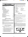
1
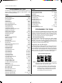
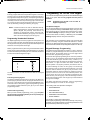
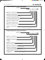
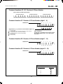
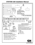
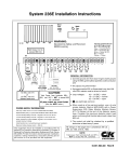
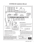
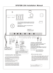
SYSTEM 236 Installation Manual Direct Conn Watch Dog DS1 JP2 WARNING: For continued protection against risk of fire, replace fuses only with fuses of same type and rating. Disconnect AC, battery, and phone cord BEFORE servicing. Slow Blow F2 0.5 A KEYPAD POWER F1 1.0 A BELL OUTPUT Capacity for emergency standby at least four hours 16.5 VAC 25 - 40 VA 50 or 60 Hz AUDIBLE 9.5 - 14 VDC Protected by Fuse F1: 3AG, 1.0 A 12 VDC, 6.5 A-H or 12 VDC, 4.0 A-H Sealed Lead-acid PHONE CORD 9.X PCF Red = Incoming Ring (R) Green = Incoming Tip (T) Grey = Seized Ring (R1) Brown = Seized Tip (T1) Blue = Tamper Orange = Tamper GENERAL INFORMATION SWITCHED AUX POWER 9.5 - 14.0 VDC Connect ground wire from door hinge to earth ground KEYPAD Do not exceed 3 keypads Protected by Fuse F2: 3AG, 0.5 A CAUTION: using 16 AWG, green jacketed, solid-conductor wire All outputs are power limited If programmed for EOL or Supervised Loop, the 2.2K Total Power from terminals BELL, AUX, and KEY+ NOT to exceed 800 mA, combined. (Also see NOTE: below.) POWER SUPPLY INFORMATION Use only 12 VDC, 6.5 A-H or 4.0 A-H sealed lead-acid battery Replace battery every 4 - 6 years with C&K Model 1265 or Model 1240 6.5 A-H standby battery time with 1 keypad is 14 hours at 300 mA 4.0 A-H standby battery time with 1 keypad is 7 hours at 400 mA Power demand for AUX POWER, keypads, and sounders not to exceed maximum ratings. Install transformer on unswitched power receptacle ohm EOL resistor (Model 9.X, 2.2K) must be at end of circuit Loop voltages: 0.00 - 1.50 VDC = short 1.60 - 3.10 VDC = normal 3.20 - 5.00 VDC = open are electrically common When used as a fire warning system, use a 4-wire smoke detector (Sentrol #ES-449C) with a Power Supervisory EOL Relay Module (System Sensor A77716 Series) at the end of the detector power loop. Consider the maximum detector alarm load when confirming that the total alarm load is less than 800 mA. Maximum battery charge current = 350 mA This equipment should be installed in accordance with the National Fire Protection Association's Standard 72 Chapter 2 (National Fire Protection Association, Batterymarch Park, Quincy, MA 02269). Printed information describing proper installation, operation, testing maintenance, evacuation planning and repair service is to be provided with the equipment. NOTE: Total power from terminals AUX and KEY+ NOT to exceed 400 mA, combined. 5-051-191-00 Rev G SYSTEM 236 Installation Manual Table of Contents Subject System 236 Terminal Label Residential Configuration (Recommended ) Installation Wiring the Panel System Start-Up Keypad Setup Addressing Keypads Factory Default Settings Programming Options (Alphabetical List) Programming the Panel Programming with the LED Keypad Programming with the Alpha Keypad Entering Hexidecimal Numbers Programming the Alpha Keypad Programming Letters & Numbers Special Function Keys Programming Options (Numerical Order) Keypad Label Drawer Telephone Line Problems Watchdog Indicator Keypad Operation Command Summary Help with Common Problems (Troubleshooting) Reducing False Alarms Warranty Information Programming Worksheets Recommended Setup (continued) 11. The communicator should not be programmed for Delay Before Dial. 12. The system must not be programmed to dial a police station. 13. Use screws (supplied) to secure cover or install a lock on the cabinet. 14. Loop Response Time should be set to 500mS. Page No. Front Cover 2 2-3 3-4 4 4-5 5 5 5-6 6-7 6 6 7 7-8 7 8 9 - 23 24 24 25 25 26 - 27 28 28 29 - 32 Zone Programming FIRE LOOP • No Delay Before Dial • 24-hour arming • Pulsing audible • Supervised - latching for heat - resetting for smoke • Not shuntable • 500mS Loop Response Time • • • • BURGLAR LOOP No Delay Before Dial NO/NC with EOL Steady audible 500mS Loop Response Time INSTALLATION Mounting The SYSTEM 236 should be mounted in a location which allows convenient access to AC power, telephone connections, and earth ground. BEFORE YOU START Scope of This Manual This manual contains basic installation and programming information for the SYSTEM 236 control/communicator. For detailed information about remote programming, please refer to the Commander II/Monitor II Operating Manual (P/N 5-051-221-00). Accuracy This manual has been carefully checked for accuracy. However, C&K SYSTEMS assumes no liability for inaccuracies or actions resulting from the use of this manual. In addition, C&K reserves the right to modify the SYSTEM 236 hardware, software, and manuals without prior notice. • Remove the circuit board from the cabinet. This will prevent possible damage to the PCB when removing the knock-outs. • • • Remove the knock-outs, as required. • Replace the circuit board, remembering to connect the ground lug to the lower left corner of the circuit board. • Reconnect the spade lug to the lower door hinge. This provides the earth ground connection for the door. Mark the screw mounting holes on the wall. Mount the cabinet at the desired height and pass the cables through the knock-outs. Earth Ground To ensure the effectiveness of the lightning and transient protection circuits, the control panel must be connected to "Earth Ground". Ideally, this should be a common ground to the power lines, telephone system, and security system. This type of ground, called a "Unified Earth Ground", provides the best protection. The ground connection, from a grounding rod, cold water pipe or other established ground point, is made to the green jacketed wire providing a ground to the panel housing. Residential Configuration The following list of options are recommended for a standard SYSTEM 236 installation in a residential environment: 1. Program the audible to sound for at least four minutes before silencing. 2. No zones should be programmed for silent alarm. 3. Fire zones should be programmed for pulsing audible alarm. 4. Burglar zones should be programmed for a steady audible. 5. Burglar loops should be programmed for EOL. 6. Entry Delay should not be greater than 45 seconds. 7. Exit Delay should not be greater than 60 seconds. 8. The Dynamic Battery Test should be enabled. 9. The Unit Status Report should be enabled. 10. The 24-hour Check-in (Test Report) should be enabled. Power Lines Telephone Lines Control Panel Power Line Earth Ground Connecting to Earth Ground 2 Telephone Earth Ground Unified Earth Ground with Bonded Ground Roots SYSTEM 236 Installation Manual WIRING THE PANEL Electromagnetic Interference Vibrating horns can produce electromagnetic interference (EMI). While EMI will not damage the SYSTEM 236, it can cause transmission errors and mis-dialing. To minimize EMI, install a 0.01 mfd, 100 V capacitor across the terminals of the horn. The capacitor must be located in the horn. STANDBY BATTERY The SYSTEM 236 is designed to operate using a 12 V, 6.5 A-H (Model 1265) or 12 V, 4.0 A-H (Model 1240) sealed lead-acid battery. Do not use non-rechargeable batteries or batteries other than sealed lead-acid. It is recommended that you replace the standby battery every four to six years. SWITCHED AUXILIARY POWER Install the battery with the terminals oriented toward the hinge side of the case and the battery mounted as close to the hinge as possible. Connect the red lead to the positive terminal of the battery and the black lead to the negative battery terminal. The panel is electronically protected against reverse battery polarity. The AUX(+) Terminal provides a positive 9.3 - 14.0 VDC for auxiliary devices that require switched power for resetting. Typical devices include glassbreak and smoke detectors. WARNING: Improper placement of the battery may result in ground trace shorting on the PCB. The Terminal labelled C provides the power common. Terminal Label: AC AC POWER Terminal Label: Aux & C ARMING STATIONS AC power is supplied from a 16.5 VAC, 25 - 40 VA transformer at 50 or 60 Hz. A UL listed Class 2 transformer must be used. Connect the secondary of the transformer to the terminals labelled AC on the SYSTEM 236. Use at least 18 AWG (1.02 mm) wire to reduce voltage drops. The primary side of the transformer must be connected to an unswitched receptacle. Do not connect primary to Ground-Fault-Interrupt (GFI) circuits. Secure the transformer to the wall. Terminal Label: KEY, C, & DATA KEY (+) Terminal (red) provides 9.8 - 14.0 VDC keypad power. C (-) Terminal (black) is common. DATA Terminal (green) is for keypad data. Maximum wire length for connecting any keypad is 500' (152 m) of 22 AWG (0.643 mm) copper wire. AC Power Failure If an AC power failure lasts more than 15 minutes, the keypads will display a system trouble and an AC failure report will be sent, if programmed. When AC is restored for five minutes, the restoral report will be sent. Precautions DO NOT share the secondary of the transformer with other devices. A foreign ground can damage the power supply, voiding the warranty. DO NOT use any transformer other than that specified in the AC POWER section above. Available Power The maximum total power available at the BELL(+), AUX(+), and KEY (+) terminals is 800 mA. The switched auxiliary and keypads share the same power bus. The combined power for the AUX(+) and KEY(+) terminals is 400 mA. Do not exceed 400 mA for all keypads and auxiliary devices. AUDIBLE OUTPUT Connect the keypad to the control panel as shown in the diagram above. The Alpha Plus keypad also has a jumper, located near the piezo, that must be installed when used with the System 236 control panel. Terminal Label: BELL & C The SYSTEM 236 is capable of addressing up to seven Alpha and four LED keypads. Each LED keypad uses 40 mA of current. Each Alpha II keypad uses 64 mA of current. See Available Power for current limitations. See pages 4 - 5 for additional information on keypad setup. The BELL(+) Terminal (Audible output) provides up to 800 mA at 9.5 - 14.0 VDC. Fuse F1 The BELL(+) Terminal is protected by a 3 AG, 1.0 A, slow-blow fuse (F1). If any fuse opens, remove AC and DC power, remove the short or overload condition, then replace the fuse before restoring power. Do not substitute a higher rated fuse. Fuse F2 KEY (+) Terminal is protected by a 3 AG, 0.5 A, fast-blow fuse. 3 SYSTEM 236 Installation Manual Tamper Switches installed in the SYSTEM 236 cabinet LOOP INPUTS Terminal Labels: Z1-Z6&C PRINTED CIRCUIT BOARD + N.C. Alarm EOL Loop N.O. Alarm - Loops 1 - 6: 0.00 - 1.50 VDC = short 1.60 - 3.10 VDC = normal 3.20 - 5.00 VDC = open Each loop is independently configured through programming. Loops can be wired with an open circuit switch, or closed circuit switch, or with a 2.2K ohm end-of-line (EOL) resistor. TB1 DOOR TAMPER SWITCH LEAD-ACID BATTERY WALL TAMPER SWITCH When programmed as EOL, either an open or a short will be reported as an alarm if the system is in an armed state. + N.C. Trouble Supervised Loop N.O. Alarm - When operated as a Supervised Loop, an open will be reported as a Trouble, whether the system is armed or disarmed. A short on a Supervised Loop will be reported as an alarm if the system is armed, but will have no effect if the system is disarmed. TELEPHONE INTERFACE Use the 9.X PCF cord to connect the SYSTEM 236 to the phone line. The cord has a modular connector on one end to plug into the wall outlet and flying leads on the other end to connect to the panel. Wire the phone connector as follows: 9.X PCF The 9.X PCF has eight flying leads on one end. C&K has designed the SYSTEM 236 cabinet to use the Ademco Model 19 tamper switch. The cabinet is constructed in order to accommodate two switches. One tamper for the cover and a second switch for a wall tamper. To install the tamper switches: 1. 2. 3. BLUE and ORANGE = tamper RED = ring (R) GREEN = tip (T) GRAY = ring seized (R1) BROWN = tip seized (T1) TAMPER SWITCH INSTALLATION YELLOW and BLACK = not used T R T1 R1 Position the tamper switch inside the cabinet at the lower right corner of the cabinet. For the wall tamper, the plunger should go through the small hole in the back of the cabinet. For the door tamper, the plunger should face out from the cabinet. Refer to the drawing below. Connect the tamper switches in series and wire the tamper terminals to a dedicated zone of the control panel. Program the dedicated zone as desired: NC, EOL, 24-hour, etc. 1 R1 = Seized Ring 2 3 4 R1 Red RJ-38X Wiring Diagram Protector Ring Green T1 = Seized Tip Once the tamper switches are installed, opening the cabinet door or removing the cabinet from the wall will result in a tamper signal at the panel. T1 8 5 7 Tip 6 Tamper Jumper House Phones 4 Incoming Telco Line SYSTEM 236 Installation Manual SYSTEM START-UP Addressing LED Keypads The LED keypad also requires an address. The address on the LED keypad is set by two jumpers (W1 and W2) on the printed circuit board. The chart below shows how to set Jumpers W1 and W2 W1 W2 to set the address of LED keypads. Any address from 8 to 11 can be used. The exact number is not important, as long as each LED keypad in the system has a different address number. In the event that two keypads are accidently given the same address, the system will fail to respond to keypad input. Refer to page 24 for assistance in correcting this problem. Fifteen minutes after the panel is powered up, it will dynamically test the standby battery by interrupting AC power for two minutes and monitoring the battery under load. Standby Battery Time with One LED Keypad AUX POWER DRAIN* 50 mA 70 mA 150 mA 300 mA 400 mA STANDBY TIME 6.5 A-H Battery 4.0 A-H Battery 32 hours 24 hours 14 hours 12 hours 24 hours 7 hours *Total power for all keypads and auxiliary If you replace the battery after a SYSTEM TROUBLE - LOW BATTERY message, you must re-test the battery under load conditions. Press [*] [6] [4] [#] to start the Dynamic Battery Test. W1 W2 Installed Installed 8 Removed Installed 9 Installed Removed 10 Removed Removed 11 KEYPAD ADDRESS FACTORY SETTINGS Voltage Variations Output voltages will vary between 9 and 14.4 VDC (worst case), depending on the load and battery condition. DEFAULT VALUES The default programming of the SYSTEM 236 will allow you to use it as a local panel without any additional programming. The actual default programming values are shown on the Programming Worksheet. KEYPAD SETUP NOTE: ALPHA KEYPAD INFORMATION If you connect power before wiring the loops, install a 2.2K EOL resistor across each loop. Combinations Installer combination: 0 1 2 3 4 5 User #1 (Master) combination: 1 2 3 4 User #2 - 6: disabled Default installer combination: yes Combination required: no Faulted Arming type: goof-proof Opening/closing: no Users authorized to send O/C reports The Alpha keypad uses a top viewing display. This means the display reads most clearly when viewed from a top angle rather than straight on or from below. Mounting the keypad at the light switch level and adjusting the viewing angle gives the best results. Adjusting the LCD Display To adjust the viewing angle, remove the keypad from the back mounting plate. Towards the bottom center of the circuit board is a small hole. Insert a small screwdriver into the hole and adjust R23, while holding the keypad at its mounting height. Adjust the potentiometer as necessary for optimum viewing. Reporting Account #1: 000000 Dialing type: pulse RPS allowed: yes ADDRESSING KEYPADS Zones Zone 1 = entry/exit delay, EOL circuit Zone 2 = interior, EOL circuit Zone 3 = doors or windows, EOL circuit Zone 4 = doors or windows, EOL circuit Zone 5 = doors or windows, EOL circuit Zone 6 = fire or smoke - supervised EOL circuit Panic soft zone: pulsed audible, non-reporting Each Alpha and LED keypad installed in the system must have an address. Addresses must not be repeated. When replacing a keypad, make sure the replacement has the same address as the previous keypad. Once all keypads have been addressed, reset the panel by pressing [Master Combination] [*] [6] [8] [#] or by removing and restoring both AC and DC power. Addressing Alpha Keypads The first time you power up the system, unaddressed Alpha keypads will display KEYPAD ADDRESS?. Press any number from 0 through 7 at each keypad. The exact number you press is not important, as long as each keypad has a different address number. The keypad will not accept values outside of this range. Should you accidentally use the same address for more than one keypad, the system will fail to properly respond to keypad input. Refer to page 24 for assistance in correcting this problem. Testing Test report interval: 7 days, disabled Timing Entry time: 60 seconds, prewarn Exit time: 30 seconds, prewarn Bell time: 5 minutes Unit Control: Local system: yes Dynamic battery test: off 5 SYSTEM 236 Installation Manual PROGRAMMING OPTIONS The following is an alphabetical listing of all SYSTEM 236 programming options, including Command Locations and Digit Positions. Digit Positions are inside parentheses ( ). Option AC Fail Report Code AC Line Frequency AC Restore Report Code Account Number Audible Time Autohome Enable Bell Fuse Fail Report Code Bell Fuse Restore Report Code Cancel Report Code Closing Report Code Combination Command Completed Programming Report Code Daily Battery Test Enable Default Installer Combination Delay Before Dial Enable Delay Before Dial Time Dial Attempts Dial Type Disable Instant/Home Exit Delay Disable Loop LEDs Door Chime Enable Entry Delay Time Event Report Receiver Select Exit Delay Time Failed To Communicate Report Code Faulted Arming Type Installer Combination Keypad RPS Enable Local System Only Loop Alarm Report Code Loop Arming Type Loop Audible Type Loop Circuit Type Loop Receiver Select Loop Response Time Loop Restore Reporting Code Loop Restore Type Loop Shunting Enable Loop Shunt Report Code Low Battery Report Code Low Battery Restore Report Code Master Code Opening Report Code Opening/Closing Report Receiver Select Panic Audible Type Panic Report Code Panic Report Receiver Select Phone Ring Type Receiver #1 Message Format Receiver #1 Phone Number Receiver #1 Receive Format Location 18 (3) 08 (6) 18 (4) 0B (1 - 6) 1B (3) 1B (6) 18 (1) 18 (2) 15 (3) 16 (3) 08 (5) 17 (4) 08 (4) 08 (3) 25 (1 - 6) 1B (4) 09 (2) 09 (6) 1B (5) 08 (1) 23 (1 - 6) 1B (1) 15 (1) 1B (2) 17 (3) 08 (2) 00 (1 - 6) 09 (4) 09 (1) 1C (1 - 6) 1D - 22 (4) 1D - 22 (5) 1D - 22 (6) 1D - 22 (2) 1D - 22 (1) 15 (5) 1D - 22 (3) 24 (1 - 6) 15 (2) 18 (5) 18 (6) 01 (1 - 4) 16 (2) 16 (1) 19 (4) 19 (1 - 2) 19 (3) 09 (5) 0A (2) 0C - 0E (1 - 6) 0A (1) Option Location Receiver #2 Message Format Receiver #2 Phone Number Receiver #2 Receive Format RPS Enable RPS Phone Number Set Test Report Countdown Timer Test Report Code Test Report Interval Test Report Receiver Select Trouble Report Code Trouble Restore Code Unit Status Report Code User Arming Type User Combinations Watchdog Reset Report Code 0A (4) 0F - 11 (1 - 6) 0A (3) 09 (3) 12 - 14 (1 - 6) A0 (1) 1A (1 - 2) 1A (4) 1A (3) 15 (4) 15 (5) 17 (1) 07 (1 - 6) 01 - 06 (1 - 4) 17 (2) PROGRAMMING THE PANEL You can program the SYSTEM 236 from either the Alpha or LED keypad, or remotely using the Commander II software. This manual provides you with a brief discription of each programming option beginning on page 9. Remote Programming information can be found in the Commander II/Monitor II Operating Manual. To Start Keypad Programming Key in the [Installer Combination][*][0][#]. The default installer combination is: 0 1 2 3 4 5. On the LED keypad, the ARM, SERVICE, and AC LED's will flash to indicate programming mode. The Alpha II keypad will display CMD DATA across the top of the LCD display to indicate programming mode. Programming with the LED Keypad Programming with the LED keypad is a one-step process. Key in the two-digit address (Command Location) followed by the desired programming values (program data), then press the [#] key to store the data. The LED keypad does not display programmed values. If you are not sure that the correct programming values have been entered, program the Command Location again. System 236 LED Keypad Layout NOTE: To program Command Location A0 with an LED keypad, remember to enter the Command Location, followed by the program data, then press the [#] key. Warning: 6 If you enter a Command Location and then press the [#] key without entering any data, the keypad will beep 5 times, indicating an error. To correct this problem, simply re-enter the Command Location and Data, then press the [#] key. SYSTEM 236 Installation Manual Programming the ALPHA Plus Keypad Programming with the Alpha Plus Keypad Entering program data with an Alpha Plus keypad is a two-step process. First, key in the two-digit address (Command Location) to be programmed and press the [#] key. The Alpha keypad displays the Command Location and the data previously stored. Enter the new data you wish to store and press the [#] key to write the data. You can also scroll through the Command Locations in numerical order by alternately pressing and releasing the [#] key. You must have the Alpha Plus keypad wired to the SYSTEM 236. Apply power to the panel. You can only program when the panel is disarmed. NOTE: The Alpha Plus Keypad You can program Alpha Plus keypads with labels for each of the 6 zones and special messages. Zone labels display during the walktest and when the [#] key is pressed during alarm memory or faults. The Service Message is displayed during AC failure, fuse failure, communication failure, low battery, or Watchdog reset. The Dealer Message displays whenever the system is disarmed. NOTE: Command Location A0 must be addressed directly. When programming this Command Location with an Alpha II keypad, the previously stored data is not displayed. To program this location, enter the Command Location followed by the [#] key. Then enter the data to be stored and again press the [#] key. Programming Hexadecimal Numbers The messages can be programmed directly from the Alpha Plus keypad or remotely using the Commander II/Monitor II software package. For detailed information about remote programming, refer to the Commander II/Monitor II Operating Manual (P/N 5-051-221-00). The Alpha keypad may be used to program the control panel. The cursor is moved to the right using the Emergency (E) key and to the left using the Police (P) key. The Fire (F) key enters a blank space and moves the cursor one position to the right. Keypad Message Programming Data is programmed into the panel using the hexadecimal number system, which consists of the digits 0 - 9 and the letters A - F. The digits 0 - 9 are entered directly from the keypad. The chart below shows how to enter the hexadecimal digits A through F. The Alpha keypad programming template is used to allow the installer to program messages and zone descriptions into the Alpha keypads. The template shown on the next page should be used when programming the keypad. To activate the keypad programming mode, enter the [Installer's Code] [*] [0] [1] [#]. Information may be entered into the keypad in the form of letters (upper and lower case), numbers (0 - 9), and 22 special symbols. All characters are displayed in the order listed above, i.e. upper and lower case letters, numbers, and special symbols. The [Space] character precedes the letter A. PROGRAMMING CONVERSIONS Hexadecimal Value A B C D E F Programming the Keypad is not the same as Keypad Programming. Key Strokes 0 1 2 3 4 5 To enter a Message or Label, use the [2] key to scroll through the characters until you reach the desired character. If you scroll past the desired character, the [8] key may be used to scroll backwards. When the desired character is displayed, press the [6] key to move the cursor to the next character position. The [4] key moves the cursor to the left. When all characters have been entered, press the [#] key to write the message and move to the next message position. Use the [0] key to move backward through the messages. The same procedure is used with both the LED and the Alpha keypads. End of Programming Segment The last two Command Locations are CL 25 and CL A0. When you press the [#] key at these locations, the program will advance to CL 26 or CL A1. These locations are not used in the SYSTEM 236. If you enter CL 26 or CL A1, either press [*][#] to exit programming, or press the Command Location followed by the [#] key for the desired programming location. The Alpha and Alpha Plus Templates, used for programming keypad messages, are shown on the next page. The Scrolling order of the Alpha Plus messages is: SERVICE MESSAGE DEALER MESSAGE To Exit Panel Programming When you have finished programming, press [*][#]. The panel will also exit the programming mode if you do not press any key within a five minute period. SOFT ZONE IDENTIFIER (C) HARDWIRED LOOP IDENTIFIERS KEYPAD ADDRESS For example, to change the Keypad Address: Enter keypad programming, as described previously, then press [*] [BYPASS]. This will step backwards one step to Keypad Address. Enter the [New Address] followed by the [#] key. 7 SYSTEM 236 Installation Manual ALPHA PLUS Programming Template ALPHA II Programming Template 1 2 3 4 5 6 7 8 9 1 2 3 4 5 6 7 8 9 0 0 NOTE: Both the Alpha and the Alpha Plus use the same procedure to program messages. If you do not press any key for 5 minutes, the keypad will automatically exit the programming mode. To Exit Alpha Keypad Programming When you have finished programming, press [*] [#]. The keypad will also exit the programming mode if you do not press any key within a five minute period. 8 CL 00 - 07 SYSTEM 236 Installation Manual Command Location 00: Installer Combination Default Values 0 1 2 3 4 5 0 0 (1) (2) (3) (4) (5) (6) Digit Positions (1) - (6): Installer Combination Combination must have 6 digits. Valid entries are 0 - 9. Command Locations 01 - 06: User Arming Combination (PIN) Default Values 01 = User #1 (Master) 02 = User #2 03 = User #3 1 2 (1) (2) 3 4 0 1 04 = User #4 05 = User #5 06 = User #6 (3) (4) Digit Position (1) - (4): Arming Combination Combination must have 4 digits. Valid entries are 0 - 9. Master Combination can be used to change other combinations. To delete a PIN, enter 0 0 0 0. Command Location 07: User Opening/Closing Report Enable Default Values 0 0 0 0 0 0 0 7 (1) Digit Position (1): User #1 O/C Report Enable 0 = No Opening and No Closing Reports 1 = Opening and Closing Reports Digit Position (2): User #2 O/C Report Enable 0 = No Opening and No Closing Reports 1 = Opening and Closing Reports Digit Position (3): User #3 O/C Report Enable 0 = No Opening and No Closing Reports 1 = Opening and Closing Reports Digit Position (4): User #4 O/C Report Enable 0 = No Opening and No Closing Reports 1 = Opening and Closing Reports Digit Position (5): User #5 O/C Report Enable 0 = No Opening and No Closing Reports 1 = Opening and Closing Reports Digit Position (6): User #6 O/C Report Enable 0 = No Opening and No Closing Reports 1 = Opening and Closing Reports 9 (2) (3) (4) (5) (6) CL 08 and 09 SYSTEM 236 Installation Manual Command Location 08: Panel Control Options Default Values 0 0 1 0 0 1 0 8 (1) (2) (3) (4) (5) (6) Digit Position (1): Disable Loop LEDs 0 = No 1 = Yes: shuts zone LEDs off after 5 minutes Digit Position (2): Faulted Arming Type 0 = Goof-proof: zones must be normal or shunted to arm 1 = Force Arm: faulted zones will be shunted at end of Exit Delay Digit Position (3): Default Installer Combination 0 = No; this enables the Pirate-GuardTM feature for added security 1 = Yes; combination reverts to factory value on power loss Digit Position (4): Daily Battery Test Enable 0 = No 1 = Yes: tests battery under load every 24 hours Digit Position (5): Combination Command 0 = No 1 = Yes; requires combination for Bypass, Instant Arm, keypad-activated RPS, and Test (central station and bell) Digit Position (6): AC Line Frequency 0 = 50 Hz 1 = 60 Hz *Pirate Guard is a trademark of C&K Systems, Inc. Command Location 09: Telco Control Options Default Values 1 1 1 1 0 1 0 9 (1) Digit Position (1): Local System Only 0 = No 1 = Yes: disables all communications except RPS Digit Position (2): Dialing Attempts 0 = 4 attempts 1 = 8 attempts 2 = 14 attempts Digit Position (3): RPS Enable 0 = No 1 = Yes: allows remote programming to start from off-premise location Digit Position (4): Enable Keypad RPS 0 = No 1 = Yes: allows remote programming to start from on-site keypad command Digit Position (5): Phone Ring Type 0 = Single ring; uniformly timed rings with long pauses between rings 1 = Double ring; rings twice quickly followed by a long pause then rings twice again Digit Position (6): Dial Type 0 = Touch Tone* DTMF 1 = Pulse Dialing *Touch Tone is a trademark of AT&T 10 (2) (3) (4) (5) (6) CL 0A and 0B SYSTEM 236 Installation Manual Command Location 0A: Communications Format Default Values 1 1 (1) (2) 0 0 1 1 0 A (3) (4) Digit Position (1): Receiver #1 Receiver Format 1 = Fast "A", 2300 Hz 2 = Slow "B", 1400 Hz 3 = SumCheck, 1400 Hz 4 = SumCheck, 2300 Hz 5 = CFSK III 6 = Ademco DTMF, 1400 Hz Digit Position (2): Receiver #1 Message Format 1 = 3/1 Extended 2 = 4/2 (2-digit reporting code) 3 = CFSK III Digit Position (3): Receiver #2 Receiver Format 1 = Fast "A", 2300 Hz 2 = Slow "B", 1400 Hz 3 = SumCheck, 1400 Hz 4 = SumCheck, 2300 Hz 5 = CFSK III 6 = Ademco DTMF, 1400 Hz Digit Position (4): Receiver #2 Message Format 1 = 3/1 Extended 2 = 4/2 (2-digit reporting code) 3 = CFSK III Valid combinations of Receiver Format and Message Format are listed below. Message Format 3/1 Extended Receiver Format All formats, except CFSK III and DTMF, 1400 Hz 4/2 (2-digit reporting) All formats, except CFSK III CFSK III CFSK III only Command Location 0B: Account Number Default Values 0 0 0 0 0 B (1) (2) (3) (4) (5) (6) Digit Positions (1) - (6): Account Number Valid entries are 0 - F. The account number is right justified. The last digit must be in Position (6). The SYSTEM 236 will read the account number using: Digit Positions (4) - (6) in 3-digit accounts Digit Positions (3) - (6) in 4-digit accounts Digit Positions (1) - (6) in 6-digit accounts Fill all unused Digit Positions with 0's. PROGRAMMING CONVERSIONS Hexadecimal Value A B C D E F 11 Key Strokes 0 1 2 3 4 5 CL 0C - 0E SYSTEM 236 Installation Manual Command Locations 0C - 0E: Receiver #1 Phone Number Order in which the numbers will be dialed Command Location 0C (1) (2) (3) (4) (5) Command Location 0D (6) (1) (2) (3) (4) (5) Command Location 0E (6) (1) (2) (3) (4) (5) (6) Command Location 0C: Receiver #1 Phone Number (digits 1 - 6) Default Values E 0 0 0 0 0 0 C (1) (2) (3) (4) (5) (6) Digit Positions (1) - (6): Receiver #1 Phone Number (Digits 1 - 6) 0 - 9 = dialing digits 0 = dial tone detect (use if more than one dial tone must be detected) 2 = * (DTMF dialing only, not used in pulse dialing) 3 = # (DTMF dialing only, not used in pulse dialing) 4 = end of number 5 = 5 second delay Digit (1) is dialed first. You must place a 4 (EON) after the last digit to be dialed. Fill in remaining Positions with "0". Zeroes after EON will not be dialed. Command Location 0D: Receiver #1 Phone Number (digits 7 - 12) Default Values 0 0 0 0 0 0 0 D (1) (2) (3) (4) (5) (6) Command Location 0E: Receiver #1 Phone Number (digits 13 - 18) Default Values 0 0 0 0 0 0 0 E (1) (2) (3) (4) (5) (6) PROGRAMMING CONVERSIONS Hexadecimal Value A B C D E F 12 Key Strokes 0 1 2 3 4 5 CL 0F - 11 SYSTEM 236 Installation Manual Command Locations 0F - 11: Receiver #2 Phone Number Order in which the numbers will be dialed Command Location 0F (1) (2) (3) (4) (5) Command Location 10 (6) (1) (2) (3) (4) (5) Command Location 11 (6) (1) (2) (3) (4) (5) (6) Command Location 0F: Receiver #2 Phone Number (digits 1 - 6) Default Values E 0 0 0 0 0 0 F (1) (2) (3) (4) (5) (6) Digit Positions (1) - (6): Receiver #2 Phone Number (Digits 1 - 6) 0 - 9 = dialing digits 0 = dial tone detect (use if more than one dial tone must be detected) 2 = * (DTMF dialing only, not used in pulse dialing) 3 = # (DTMF dialing only, not used in pulse dialing) 4 = end of number 5 = 5 second delay Digit (1) is dialed first. You must place a 4 (EON) after the last digit to be dialed. Fill in remaining Positions with "0". Zeroes after EON will not be dialed. Command Location 10: Receiver #2 Phone Number (digits 7 - 12) Default Values 0 0 0 0 0 0 1 0 (1) (2) (3) (4) (5) (6) Command Location 11: Receiver #2 Phone Number (digits 13 - 18) Default Values 0 0 0 0 0 0 1 1 (1) (2) (3) (4) (5) (6) PROGRAMMING CONVERSIONS Hexadecimal Value A B C D E F 13 Key Strokes 0 1 2 3 4 5 CL 12 - 14 SYSTEM 236 Installation Manual Command Locations 12 - 14: RPS Phone Number Order in which the numbers will be dialed Command Location 12 (1) (2) (3) (4) (5) Command Location 13 (6) (1) (2) (3) (4) (5) Command Location 14 (6) (1) (2) (3) 0 0 (4) (5) (6) Command Location 12: RPS Phone Number (digits 1 - 6) Default Values E 0 0 0 1 2 (1) (2) (3) (4) (5) (6) Digit Positions (1) - (6): RPS Phone Number (Digits 1 - 6) 0 - 9 = dialing digits 0 = dial tone detect (use if more than one dial tone must be detected) 2 = * (DTMF dialing only, not used in pulse dialing) 3 = # (DTMF dialing only, not used in pulse dialing) 4 = end of number 5 = 5 second delay Digit (1) is dialed first. You must place a 4 (EON) after the last digit to be dialed. Fill in remaining Positions with "0". Zeroes after EON will not be dialed. Command Location 13: RPS Phone Number (digits 7 - 12) Default Values 0 0 0 0 0 0 1 3 (1) (2) (3) (4) (5) (6) Command Location 14: RPS Phone Number (digits 13 - 18) Default Values 0 0 0 0 0 0 1 4 (1) (2) (3) (4) (5) (6) PROGRAMMING CONVERSIONS Hexadecimal Value A B C D E F 14 Key Strokes 0 1 2 3 4 5 CL 15 and 16 SYSTEM 236 Installation Manual Command Location 15: Event Reports Default Values 1 9 D F E 1 5 (1) (2) (3) (4) (5) Digit Position (1): Event Report Receiver Select Shunts, All Restores, Status, Trouble, and Cancel 2 = Receiver 2 only 3 = Receiver 1 and Receiver 2 (Dual Reporting) 0 = Receiver 1 with Receiver 2 as back-up 1 = Receiver 1 only Digit Position (2): Loop Shunt Report Code Valid entries are 1 - F. This is a 1-digit reporting code used for all loops. For 2-digit reporting formats, the loop number will be automatically added as an extension. Programming a "0" in Position (2) disables shunt reporting for all loops. Digit Position (3): Cancel Report Code Valid entries are 1 - F. This is a 1-digit reporting code used for all loops. For 2-digit reporting formats, the User ID Number will be automatically added as an extension. Programming a "0" in Position (3) disables cancel reporting for all loops. Digit Position (4): Trouble Report Code Valid entries are 1 - F. This is a 1-digit reporting code used for all loops. For 2-digit reporting formats, the loop number will be automatically added as an extension. Programming a "0" in Position (4) disables trouble reporting for all loops. Digit Position (5): Loop Restore Reporting Code Restores are sent for alarm, shunt, and trouble. Valid entries are 1 - F. This is a 1-digit reporting code used for all loops. For 2-digit reporting formats, the loop number will be automatically added as an extension. Programming a "0" in Position (5) disables restore reporting for all loops. Command Location 16: Opening/Closing Reports Default Values 1 B C 1 6 (1) Digit Position (1): Opening/Closing Receiver Select 0 = Receiver 1 with Receiver 2 as back-up 1 = Receiver 1 only 2 = Receiver 2 only 3 = Receiver 1 and Receiver 2 (Dual Reporting) Digit Position (2): Opening Report Code Valid entries are 1 - F. This is a 1-digit reporting code. For 2-digit reporting formats, the User ID Number will be automatically added as an extension. Programming a "0" in Position (2) disables opening reports. Digit Position (3): Closing Report Code Valid entries are 1 - F. This is a 1-digit reporting code. For 2-digit reporting formats, the User ID Number will be automatically added as an extension. Programming a "0" in Position (3) disables closing reports. 15 (2) (3) CL 17 and 18 SYSTEM 236 Installation Manual Command Location 17: Status Events Reporting Codes - #1 Default Values 0 0 (1) (2) 0 0 1 7 (3) (4) Digit Position (1): Unit Status Report Code This is a global command for CL 17 and CL 18. If Position (1) is programmed with a "0", all Status Reports in CL 17 and CL 18 will be disabled. If Position (1) is programmed with any value other than 0, all Status Reports in CL 17 and CL 18 which have been enabled (not programmed with 0) will send reports. Status Reporting Codes will be a 2-digit code. The first digit is the contents of CL 17 (1) and the second digit is the respective Report Code programmed into the panel. Digit Position (2): Watchdog Reset Report Code 0 = No 1 - F = Yes: this report code sent after each Watchdog reset Digit Position (3): Failed To Communicate Report Code 0 = No 1 - F = Yes: this report code sent after each failure to communicate Digit Position (4): Completed Programming Report Code 0 = No 1 - F = Yes: this report code sent on completion of panel programming Command Location 18: Status Events Reporting Codes - #2 Default Values 0 0 0 0 0 0 1 8 (1) (2) (3) (4) (5) (6) Digit Position (1): Bell Fuse Fail Report Code 0 = No 1 - F = Yes: this report code sent at Bell Fuse failure Digit Position (2): Bell Fuse Restore Report Code 0 = No 1 - F = Yes: this report code sent at Bell Fuse restoral Digit Position (3): AC Fail Report Code 0 = No 1 - F = Yes: this report code sent at AC failure Digit Position (4): AC Restore Report Code 0 = No 1 - F = Yes: this report code sent at AC restoral Digit Position (5): Low Battery Report Code 0 = No 1 - F = Yes: this report code sent at low battery voltage PROGRAMMING CONVERSIONS Hexadecimal Value Digit Position (6): Low Battery Restore Report Code 0 = No 1 - F = Yes: this report code sent when battery voltage returns to normal 16 A B C D E F Key Strokes 0 1 2 3 4 5 CL 19 and 1A SYSTEM 236 Installation Manual Command Location 19: Panic Report Default Values 0 0 (1) (2) 0 0 (1) (2) 1 1 1 9 (3) (4) Digit Positions (1) - (2): Panic Report Code Valid entries are 0 - F Program a "00" to disable Panic Reports. Digit Position (3): Panic Receiver Select 0 = Receiver 1 with Receiver 2 as back-up 1 = Receiver 1 only 2 = Receiver 2 only 3 = Receiver 1 and Receiver 2 (Dual Reporting) Digit Positions (4): Panic Audible Type 1 = Pulsing 2 = Steady 3 = Chirp 4 = Silent Command Location 1A: Test Report Default Values 1 5 1 A (3) (4) Digit Positions (1) - (2): Test Report Code Valid entries are 0 - F Program a "00" to disable Test Reports. Digit Position (3): Test Report Receiver Select 0 = Receiver 1 with Receiver 2 as back-up 1 = Receiver 1 only 2 = Receiver 2 only 3 = Receiver 1 and Receiver 2 (Dual Reporting) Digit Position (4): Test Report Interval 0 = Manual (See NOTE) 1 = 1 hour 2 = 4 hours 3 = 12 hours 4 = 24 hours 5 = 7 days 6 = 14 days 7 = 30 days 8 = 1 hour, if armed 9 = 4 hours, if armed 0 = 12 hours, if armed 1 = 24 hours, if armed NOTE: When the Test Report Interval is programmed with a "0", automatic Test Reporting is disabled. To send a Manual Test Report to the Central Station, refer to the System Test procedures outlined in the Keypad End User Manual supplied with this System. PROGRAMMING CONVERSIONS Hexadecimal Value A B C D E F 17 Key Strokes 0 1 2 3 4 5 CL 1B and 1C SYSTEM 236 Installation Manual Command Location 1B: Panel Timing Default Values 3 2 2 1 0 0 1 B (1) (2) (3) (4) (5) (6) Digit Position (1): Entry Delay 1 = 10 seconds 2 = 30 seconds 3 = 60 seconds 4 = 90 seconds 5 = 120 seconds 6 = 150 seconds Digit Position (2): Exit Delay 1 = 10 seconds 2 = 30 seconds 3 = 60 seconds 4 = 90 seconds 5 = 120 seconds 6 = 150 seconds Digit Position (3): Audible Time 1 = 2 minutes 2 = 5 minutes 3 = 10 minutes 4 = 15 minutes 5 = 30 minutes Digit Position (4): Delay Before Dial Time 1 = 10 seconds 2 = 20 seconds 3 = 30 seconds 4 = 40 seconds 5 = 50 seconds 6 = 60 seconds Digit Position (5): Disable Instant/Home Exit Delay 0 = No 1 = Yes: no exit delay when system is Instant, Home, or Instant/Home armed Digit Position (6): Autohome Enable 0 = No 1 = Yes: interior zones automatically shunted when the system is armed and the exit door is not used Command Location 1C: Loop Alarm Reporting Codes Default Values 1 2 3 4 5 6 1 C (1) Digit Position (1): Loop 1 Alarm Report Code (2) (3) (4) (5) (6) Valid entries are 1 - F. Zone number is automatically added as the second digit. Program a "0" to disable Alarm Reports for this loop. Digit Position (2): Loop 2 Alarm Report Code See Digit Position (1) for programming information. Digit Position (3): Loop 3 Alarm Report Code See Digit Position (1) for programming information. Digit Position (4): Loop 4 Alarm Report Code See Digit Position (1) for programming information. Digit Position (5): Loop 5 Alarm Report Code PROGRAMMING CONVERSIONS See Digit Position (1) for programming information. Hexadecimal Value Digit Position (6): Loop 6 Alarm Report Code A B C D E F See Digit Position (1) for programming information. 18 Key Strokes 0 1 2 3 4 5 CL 1D - 23 SYSTEM 236 Installation Manual Command Locations 1D - 22: Loop Control 1D = Loop 1 1E = Loop 2 1F = Loop 3 20 = Loop 4 21 = Loop 5 22 = Loop 6 Default Values 1 1 1 2 2 0 1 D Digit Position (1): Loop Response Time (1) (2) (3) (4) (5) (6) 0 = 10 milliseconds 1 = 500 milliseconds Digit Position (2): Loop Receiver Select 0 = Receiver 1 with Receiver 2 as back-up 1 = Receiver 1 only 2 = Receiver 2 only 3 = Receiver 1 and Receiver 2 (Dual Reporting) Digit Position (3): Loop Restore Type 0 = No restoral 1 = Return to normal 2 = Return to normal, bell silences 3 = Return to normal, system disarmed Digit Position (4): Loop Arming Type 0 = Instant 1 = Interior 2 = Delay 3 = Long Delay 4 = 24 hours (always armed) Digit Position (5): Loop Audible Type 1 = Pulsing 2 = Steady 3 = Chirp 4 = Silent with no LED 5 = Silent with LED Digit Position (6): Loop Circuit Type 0 = EOL: alarm on open or short 1 = Supervised: trouble on open; alarm on short; follows bell time 2 = Supervised, bell latched: trouble on open; alarm on short; bell latched NOTE: A Loop programmed as type 1 or 2 will report any open as a Trouble condition, regardless of panel armed status. Command Location 23: Door Chime Enable Default Values 0 0 0 0 0 0 2 3 (1) Digit Position (1): Loop 1 Door Chime Enable 0 = No 1 = Yes: keypads beep two seconds when loop is faulted Digit Position (2): Loop 2 Door Chime Enable Refer to Digit Position (1) for programming options. Digit Position (3): Loop 3 Door Chime Enable Refer to Digit Position (1) for programming options. Digit Position (4): Loop 4 Door Chime Enable Refer to Digit Position (1) for programming options. Digit Position (5): Loop 5 Door Chime Enable Refer to Digit Position (1) for programming options. Digit Position (6): Loop 6 Door Chime Enable Refer to Digit Position (1) for programming options. 19 (2) (3) (4) (5) (6) CL 24 - 25 and A0 SYSTEM 236 Installation Manual Command Location 24: Shunting Enable Default Values 1 1 1 1 1 1 2 4 (1) Digit Position (1): Loop 1 Shunting Enable 0 = No: makes this zone a priority zone (not shuntable) 1 = Yes: authorized users can bypass or force arm (2) (3) (4) (5) (6) Digit Position (2): Loop 2 Shunting Enable Refer to Digit Position (1) for programming options. Digit Position (3): Loop 3 Shunting Enable Refer to Digit Position (1) for programming options. Digit Position (4): Loop 4 Shunting Enable Refer to Digit Position (1) for programming options. Digit Position (5): Loop 5 Shunting Enable Refer to Digit Position (1) for programming options. Digit Position (6): Loop 6 Shunting Enable Refer to Digit Position (1) for programming options. Command Location 25: Delay Before Dial Enable Default Values 0 0 0 0 0 0 2 5 (1) Digit Position (1): Loop 1 Delay Before Dial Enable (2) (3) (4) (5) (6) 0 = No 1 = Yes: this loop will delay dialing on alarm for time programmed in CL 1B (4) Digit Position (2): Loop 2 Delay Before Dial Enable Refer to Digit Position (1) for programming options. Digit Position (3): Loop 3 Delay Before Dial Enable Refer to Digit Position (1) for programming options. Digit Position (4): Loop 4 Delay Before Dial Enable Refer to Digit Position (1) for programming options. Digit Position (5): Loop 5 Delay Before Dial Enable Refer to Digit Position (1) for programming options. Digit Position (6): Loop 6 Delay Before Dial Enable Refer to Digit Position (1) for programming options. Command Location A0: Test Report Countdown Timer A 0 (1) Digit Position (1): Set Test Report Countdown Timer This command sets the time when the first Test Report is transmitted to the central station. The SYSTEM 236 will use this transmission time whenever it is powered up or the CPU is reset (unless CL A0 is reprogrammed). 0 = 14 hours 0 = 1/4 hour 5 = 4 hours 1 = 16 hours Example: 1 = 1/2 hour 6 = 6 hours 2 = 18 hours The time is 1500 hours (3:00 pm). You want the first Test Report to 2 = 1 hour 7 = 8 hours 3 = 20 hours transmit at 0100 hours (1:00 am). 3:00 pm + 10 hours = 1:00 am. 3 = 2 hours 8 = 10 hours 4 = 22 hours Program the value "8" in Position (1) of CL A0. 4 = 3 hours 9 = 24 hours 5 = 24 hours 20 SYSTEM 236 Installation Manual FCC NOTICE TESTING Once the installation is complete, connect AC and DC power. Complete programming, if required. Test all panel operations. TO THE INSTALLER Regular maintenance and inspection (at least monthly) by the installer, and frequent testing by the user, are vital to the continuous and satisfying operation of any alarm system. The installer should assume the responsibility for developing and offering a regular maintenance program to the user, as well as acquainting the user with the proper operation and limitations of the alarm system and its component parts. Recommendations must include a specific program of regular testing (at least weekly) to insure that the system is operating properly. TELEPHONE LINE PROBLEMS In the event of telephone line problems, disconnect the SYSTEM 236 by removing the modular connector plug from the Telco interface jack. Do not disconnect the connection inside the SYSTEM 236 cabinet. Doing so will prevent the premise phones from operating. If the phone works correctly after the control panel has been disconnected from the phone line, the control panel has a problem and should be returned for repair. If the phone does not work correctly after the control panel has been disconnected from the phone line, notify the telephone company and request prompt repair. The user may not under any circumstances, in or out of warranty, attempt any service or repairs on the SYSTEM 236. The control panel must be returned to C&K SYSTEMS or an authorized service agency for repairs. WATCHDOG INDICATOR DS1 The SYSTEM 236 is protected by an advanced circuit that constantly monitors the microprocessor. As long as the panel is powered and operating normally, the DS1 LED on the circuit board will flash. If the Watchdog circuit detects a failure, it will attempt to reset the panel and make the DS1 LED light steadily. If the panel resumes normal operations after a Watchdog reset, clear the DS1 LED by resetting the panel or pressing [*] [1] [#], then test the system. No further action is required. WATCH DOG If the panel does not operate properly after a Watchdog reset, call the C&K Technical Support Hotline at 1-800-227-8065. WARNING: This device is intended to be installed by a professional alarm installer. The user shall be cautioned that changes or modifications not expressly approved by C&K SYSTEMS could void the user's authority to operate the equipment. This equipment complies with FCC Rules, Part 68. On the outside of this equipment is a label that contains, among other information, the FCC Registration Number and Ringer Equivalence Number (REN) for this equipment. If requested, provide this information to your telephone company. The REN is useful to determine the quantity of devices you may connect to your telephone line and still have all of those devices ring when your number is called. In most, but not all areas, the sum of the RENs devices should not exceed five (5.0). To be certain of the number of devices you may connect to your line, as determined by the REN, you should call your local telephone company to determine the maximum REN for your calling area. Should you experience trouble with the telephone lines, disconnect the equipment from the line to determine the source of the trouble. If it is determined that the equipment is malfunctioning, discontinue its use until the malfunction has been corrected. Any repairs or alterations made by the user to this equipment, or equipment malfunctions, may give the telephone company cause to request the user to disconnect the equipment. Repairs to this equipment should be made by an authorized agent of C&K Systems, Inc. Contact your local alarm installation company for service. Should this equipment cause harm to the telephone network, the telephone company may temporarily discontinue your service. If possible, they will provide you with advance notice. Otherwise they will notify you as soon as possible. The telephone company will also advise you of changes in its facilities, equipment, operations or procedures which could affect the operation of your equipment, allowing you the opportunity to maintain uninterrupted service. You will also be advised of your right to file a complaint with the FCC. This equipment must not be used on party lines or coin operated phone lines. FCC Part 15 Notice This equipment has been tested and found to comply with the limits for Class B digital devices, pursuant to Part 15 of the FCC Rules. These limits are designed to provide reasonable protection against harmful interference in a residential installation. This equipment generates, uses, and can radiate radio frequency energy, and if not installed and used in accordance with the instructions, may cause harmful interference to radio communications. However, there is no guarantee that interference will not occur in a particular installation. If this equipment does cause harmful interference to radio or television reception, which can be determined by turning the equipment off and on, the user is encouraged to try to correct the interference by one or more of the following measures: Reorient the radio/television antenna; Connect the AC transformer to a different outlet so that the equipment and radio/television are on different branch circuits; Relocate the equipment with respect to the radio/television; Consult the dealer or an experienced radio/television technician for help. FCC Registration Number: C2DCHN-75290-AL-E Ringer Equivalence: 0.3B CANADIAN EMISSION REQUIREMENTS This Class B digital apparatus meets all requirements of the Canadian Interference-Causing Equipment Regulations. Cet appareil numérique de la classe B respecte toute les exigences du Règlement sur le matériel brouilleur du Canada. 21 SYSTEM 236 Installation Manual Keypad Operation Command Summary The majority of the keypad commands apply equally to the LED and Alpha II keypads. Some keypad commands, however, apply to the LCD keypad only. The following Keypad Commands apply to both the LED and Alpha II keypads: Function Arm/Disarm Bypass Zone (n) Chime On/Off Change Combo Clear Alarm Memory Entry/Exit Pre-Alarm Error Tones Exit Programming Home Arm Instant Arm Instant Home Arm Keypad Activated RPS Keypad Tone Disable Panic Alarm Reset Aux Power Reset Test Test Test Test - Panel Battery Bells Central Station Local Walk Test Comments Keystroke Sequence Delays active [n] is zone # 1 - 6; Combo may be required [Combination] [#] [Combination] [*] [2] [n] [#] [*] [5] [#] Must be done from Master Combination [Master Combo] [*] [0] [#] [User No.] [#] (User #1) [New Combo][#][New Combo][#] [*] [1] [#] Toggle Pre-Alarm tones on and off [*] [5] [2] [#] Toggle Error Tones on and off [*] [5] [4] [#] [*] [#] All interior zones are shunted simultaneously; [Combination] [*] [4] [#] Exterior zones armed; Combo may be required Converts all delayed zones to instant; Combo [Combination] [*] [7] [#] may be required Arms exterior zones, shunts interior zones, [Combination] [*] [4] [7] [#] (or) Entry delays converted to Instant; Combo [Combination] [*] [7] [4] [#] may be required If enabled, CL 09(4); Combo may be required [Combination] [*] [0] [2] [#] Toggle Entry/Exit Pre-Alarm and Confirmation/ [*] [5] [1] [#] Error tones on and off Keypad activated [9] (Hold for 3 seconds) If resettable devices are connected to [*] [6] [2] [#] Terminals labelled AUX (+) and C Panel must be disarmed [Master Combination] [*] [6] [8] [#] Use after correcting Low Battery problem [*] [6] [4] [#] Combo may be required [Combination] [*] [6] [3] [#] Combo may be required [Combination] [*] [6] [1] [#] Combo may be required [Combination] [*] [6] [0] [#] NOTE: For additional information about Combination Command requirements, see page 26 and CL 08 (5). The following Keypad Commands apply to the Alpha II keypad only: Function Comments Keystroke Sequence Arm Tones Toggle On/Off Audible Feedback Toggle Backlight Toggle On/Off Display Keypad Model & Revision Number Chime Toggle Pre-warn Toggle On/Off [*] [*] [*] [*] [5] [5] [8] [9] [4] [#] [1] [#] [#] [#] [*] [5] [3] [#] [*] [5] [2] [#] The following Keypad Commands are Installer Only Commands: Function Alpha Keypad Programming Alpha Keypad Test Kill/Revive Panel Panel Programming Comments Keystroke Sequence Start Programming the Keypad Keypad must be disconnected from panel Panel must be disarmed Start Programming the Panel 22 [Installer Combination] [*] [0] [1] [#] [*] [6] [7] [#] [Installer Combination] [*] [6] [9] [#] [Installer Combination] [*] [0] [#] SYSTEM 236 Installation Manual Survey of Most Common Questions The following is a summary of the questions most frequently asked of our Technical Support Department. QUESTION: How do I program the panel with the LED keypad? ANSWER: To program with the LED keypad, enter the Command Location to be programmed, the Data to be programmed and the press the [#] key. (See also page 6.) For Example: To program User #2 with a PIN of 4-5-3-5, enter the following keystrokes: CL [0][2] Data to Store [4] [5] [3] [5] Write Data [#] Question: Answer: tion] How do I access Alpha Keypad Programming to enter Zone Labels? To begin Alpha Keypad Programming (you cannot program the LED keypad), enter [Installer Combina- Question: Answer: How do I interpret a Trouble on the LED keypad? How do I clear a Trouble on the LED keypad? A number of conditions may cause the Service LED to light. See the chart below for additional information. Service LED Power LED Zone LED's Cause [*] [0] [1] [#]. Then scroll to the desired message location. (See also page 7.) Flash Slow On On On Flash Fast On On On Off Flash Slow On On Off Flash Slow Off Off Off Off Watchdog Zone Trouble AC Failure Low Battery System Trouble (Comm Fail) System Trouble (Bell Fuse Fail) Question: Answer: tional How do I enter hexidecimal numbers when using keypad programming? Hexidecimal values are entered through the use of the [*] key and one of the digits [0] - [5]. For addi- Question: Answer: What is an "Interface error 1" and how do I correct the error? This error is caused by a problem with the Data line (Green wire) between the panel and the keypad. Check the connection to ensure that the wire is not pinched or loose. Also try disconnecting all keypads from the panel (one at a time), resetting the panel after each keypad is removed. Remember, to reset the panel press: [Master Code] [*] [6] [8] [#]. Question: Answer: How do I reset Alarm Memory? To Clear Alarm Memory, press [*] [1] [#]. Question: Answer: How do I address an Alpha Keypad for the first time? If you have an Alpha keypad that has never been addressed, when power is initially applied, the display will read KEYPAD ADDRESS?. To enter the address, simply press a number between 0 and 7. Remove panel power for 3 seconds and then re-apply power to reset the system. For additional information about Keypad addressing, see page 5. help with entering hexidecimal numbers, refer to pages 6 - 7. The hexidecimal conversion chart is also found at various locations throughout the programming section of the manual. NOTE: Question: Answer: If operating at or near the limit of AUX Power and Keypad Power, you may need to remove power for up to 30 seconds in order for the system to reset properly. Why do my loops fail to respond after changing the programming? In order for the panel to recognize the programming changes for the loops, either the loops have to be tripped and restored or the panel must be reset ( [Master Combination] [*] [6] [8] [#] ). 23 SYSTEM 236 Installation Manual Question: Answer: How do I interpret the Unit Status Reports? Can the codes be changed? Status Reporting is divided between CL 17 and CL 18. Each Reporting Code of the Unit Status Report is a two-digit code. The first digit is the data programmed into CL 17 Digit Position (1) and may be any value from 0 - F. The second digit is the data programmed into the respective Status Report Code. Please note that programming a 0 into CL 17 (1) will disable all Unit Status Reports in CL 17 and CL 18. Additional information about Unit Status Reporting Codes can be found on page 16 in the programming section. Question: How do I enter Receiver and RPS Phone Numbers? Why do I have to enter the E at the end of the number? The System 236 is designed to handle phone numbers up to 18 digits long, but the firmware can only handle 6 digits per Command Location. This means that 3 Command Locations are required to store a phone number. With variations in number length and special characters which may need to be included, the software needs some method of determining the end of the number. The E (entered by pressing Answer: [*][4]) tells the software that it has reached the end of the phone number and to ignore any additional digits. For Example: To program the panel for Receiver #1 with a phone number of 555-1212 and disable Command Location 0C Command Location 0D C 7 0 5 5 5 (1) (2) (3) (4) (5) (6) 1 (1) Command Location 0E 2 1 2 E 0 0 0 0 0 0 0 (2) (3) (4) (5) (6) (1) (2) (3) (4) (5) (6) NOTE: Entering [*] [2] in CL 0C (1) will display the value "C" and entering [*] [4] in CL 0D (5) will display the value "E". Question: Answer: nect the Question: Answer: How can I correct the problem of two Alpha keypads with the same address? When two keypads have been given the same address, a conflict occurs on the data bus since two keypads are trying to communicate at the same time. The only way to correct the problem is to disconboth keypads and then re-address one of them, making sure that the address is not used by any other keypad. To re-address the keypad, enter Alpha Keypad Programming ( [Installer Combination] [*] [0] [1] [#] ) and scroll backward one step ( [*] [BYPASS] ). Then enter the new address. Don't forget to reset panel ([Master Code] [*] [6] [8] ]#]) after changing the address, so the panel knows how to properly address the keypad. For additional information about keypad addressing, see page 5. Why can't my panel communicate with the Central Station? There are several reasons for the panel not communicating. The first place to look is CL 09 (1). This is the Telco Control, if Digit Position (1) is programmed with a 1, all communication except RPS is disabled. If 09 (1) is programmed with a 0, check to ensure that all of the following parameters are properly set: Account Number 1 is programmed into CL 0B Receiver #1 Phone Number is correctly programmed into CL 0C - 0E Receiver Format and Message Format agree CL 0A Telco Control Options (CL 09) are correctly programmed The RJ-31X jack is correctly wired (pins 4 & 5 are not switched with 1 & 8) 24 SYSTEM 236 Installation Manual Recommendations for Reducing False Alarms The recommendations contained in this section are designed to assist you in reducing false alarms. The first column contains the Command Locations and Digit Positions in parentheses ( ). The second column is the recommended program option followed by a brief explanation. Program Option CL Program Function Arming/Combination 08 (5) Options Combination Command Comments This feature is enabled to prevent unauthorized users from activating certain keypad functions. When activated, this command will require a valid User Combination to perform such functions as Bypassing a Zone, Group Bypassing, Keypad Activated RPS, Central Station and Bell Testing, and Instant Arming. For more help with commands requiring User Combinations, see page 22(Command Summary). Loop Control 1D - 22 (1) Loop Response Time This option determines the response time of the loop itself. It acts as a buffer on the loop to minimize the possibility of fast acting sensors, such as swingers or window foil, producing false alarms. Loop Control 1D - 22 (3) Loop Restore Type This option is used in conjunction with CL 15 Digit Position (5), Restore Reporting Code, and CL 15 (1), Event Report Receiver Select. The panel can be programmed to send a Restoral Report only when the loop is normal and the system is disarmed. With this arrangement, any loop which is triggered multiple times while armed will only send one alarm report until the system is disarmed. This prevents the system from tieing up the phone line with continuous alarm and restoral reports. Loop Control 1D - 22 (4) Loop Arming Type There may be occassion where it is desirable to program all doors and interior points as delayed. Or you may need to program interior zones to be delayed only during the Entry/Exit Delay Time. This Command Location allows a variety of Arming Types to help minimize false alarms. Event Reporting 15 (1 & 3) Cancel Report Code/Cancel Report Receiver Select This feature should always be enabled on reporting systems, especially if the system does not send Opening and Closing Reports. A Cancel Report is sent to the monitoring station in the event that an Authorized User clears the alarm while the bell is still active. The Cancel Report Code (Digit Position 3) is actually a two-digit code with the first digit being programmed by the installer and the second digit being the User ID # when the report is sent. Digit Position (1) determines which receiver gets the Cancel Report. Loop Switches 25 (1 - 6) This option programs the loops to have a delay after they are triggered to allow the User time to shut down the system in the event of an accidental triggering of the zone. The amount of time is determined by the value programmed into CL 1B Digit Position (4). The time delay may be between 10 and 60 seconds, in 10 second intervals. Delay Before Dial 25 SYSTEM 236 Installation Manual THE LIMITATIONS OF YOUR ALARM SYSTEM While the SYSTEM 236 is an advanced design security system, it does not offer guaranteed protection against burglary, fire, or other losses. Any alarm system, whether commercial or residential, is subject to compromise or failure-to-warn for a variety of reasons. These include: . . . . Intruders may gain access through unprotected openings or have the technical sophistication to bypass an alarm sensor or disconnect an alarm warning device. Intrusion detectors, smoke detectors, and many sensing devices will not operate without power. Devices powered by AC will not work if their AC power supply is off for any reason and their backup batteries are missing, dead, or improperly installed. . Alarm warning devices such as sirens, bells, and horns may not alert people or wake up sleepers if they are located on the other side of closed or partly closed doors. If warning devices are on a different level of the residence from bedrooms, there are less likely to waken or alert people inside the bedrooms. . Telephone lines needed to transmit alarm signals from a premise to a central monitoring station may be out of service or temporarily out of service. Telephone lines are subject to compromise by sophisticated methods of attack. . Smoke detectors used in conjunction with the alarm system may not sense fires that start where smoke cannot reach the detectors, such as chimneys, walls, or roofs, or on the other side of closed doors. Smoke detectors also may not sense a fire on another level of the residence or building. A second-floor detector, for example, may not sense a first-floor or basement fire. Finally, smoke detectors have sensing limitations. No smoke detector can sense every kind of fire every time. In general, detectors may not always warn you about fires caused by carelessness and safety hazards, like smoking in bed, violent explosions, escaping gas, improper storage of flammable materials, overloaded electronic circuits, children playing with matches, arson, etc. The most common cause of an alarm system not functioning properly when an intrusion or fire occurs is inadequate maintenance. Your alarm system should be tested weekly to make sure all sensors are operating properly. The SYSTEM 236 and all keypads should also be tested. Installing an alarm system may make you eligible for lower insurance rates. However, an alarm system is not a substitute for insurance. Homeowners, property owners, and renters should continue to insure their lives and property. 5-051-191-00, Rev G C&K is a registered trademark of C&K Components, Inc. © 1998 C&K Systems, Inc. All Rights Reserved 26 SYSTEM 236 Installation Manual 236 Programming Worksheet Client: SYSTEM 236 Phone Number: Address: Installer: Date: CONTROL LOCATION: VOLTS AC volts (AC terms): KEYPADS Address AUX POWER VOLTS (terms AUX+ and C): 0 1 BATTERY VOLTS Under load - AC off: 2 BREAKER # AND LOCATION: 3 CURRENT Keypads 4 5 AUX POWER 0 0 1 0 3 1 2 3 1 2 3 4 0 0 5 0 7 0 9 0 1 0 0 0 1 7 = 0 0 6 + TOTAL (400 mA allowed): 0 Location 0 0 0 1 0 4 5 Installer Combination 0 User #1 - Master 0 2 User #3 0 4 User #5 Name: 0 Name: 0 0 0 1 0 0 Name: 0 1 0 6 User Arming Type 0 8 Telco Control Options 0 A 27 0 0 0 0 0 0 0 0 User #2 User #4 User #6 Name: Name: 0 0 0 1 0 1 1 1 1 0 Name: 1 Panel Control Options Communications Format SYSTEM 236 Installation Manual 0 0 0 0 0 0 0 B Account Number Phone #1 (1st 6 digits) E 0 0 0 0 0 (Middle 6 digits) 0 C 0 0 0 0 0 0 0 0 0 1 1 0 0 0 1 5 1 7 0 0 1 9 1 B 1 D 1 F 2 1 2 3 2 5 3 1 1 1 0 0 9 0 0 2 1 1 1 0 0 D 0 1 2 1 1 1 0 0 F 0 1 1 2 0 0 0 0 E 0 0 0 0 1 0 0 0 Event Reports 1 6 8 Panic/Duress 1 A 2 0 0 0 0 0 0 0 0 0 Timing/Keypad Control 1 C Loop 1 Control 1 E Loop 3 Control 2 0 Loop 5 Control 2 2 Door Chime Enable 2 4 Delay Before Dial 28 0 0 0 0 0 0 0 E 0 0 1 0 0 0 1 0 3 1 2 0 0 (Last 6 digits) 0 Status Event Reporting Codes #1 2 0 (Last 6 digits) 0 0 0 (Middle 6 digits) 0 2 1 0 0 RPS Phone (1st 6 digits) 0 (Last 6 digits) 0 (Middle 6 digits) 0 F E 0 D Phone #2 (1st 6 digits) E 0 1 0 0 0 4 1 B C 0 0 0 0 0 0 1 5 1 2 3 4 5 6 1 1 1 1 2 0 1 1 1 0 2 0 1 1 0 4 1 1 1 1 1 1 1 1 Opening/Closing Reports 0 0 Status Events Reporting Codes - #2 Test Report Loop Alarm Reporting Codes Loop 2 Control Loop 4 Control Loop 6 Control Shunt Enable