1
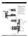
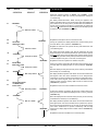
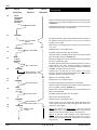
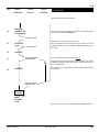
CPA6
Installation & User Guide
Compatible Equipment
CPA6 OM - Output Module
9040 - Loudspeaker
DC54/58 - Digital Communicators (Stand Alone Only)
496524 Issue A
1 of 16
CPA6
CPA6
Overview
Introduction
Facilities
The CPA6 multizone alarm control panel has been
manufactured under exacting quality control
standards and incorporates the latest proven
electronic technology and high quality components to
assure outstanding and lasting performance.
The panel offers the following facilities as standard:-
T h e u n i t co mp lie s w it h B ritish Standards
recommendations (BS4737 Parts 1 and 2).
The micro-processor based panel caters for alarm
systems of up to sixty circuits and is easily installed to
provide highly effective system control and monitoring.
Its main advantages include:l
l
l
l
l
l
SIMPLIFIED INSTALLATION WIRING, reduced time
and costs.
ENGLISH TEXT DISPLAY, shows all faults, alarms and
operating directions.
EVENT MEMORY, related to date and time , stores
all events, alarms, opening and setting etc., in
reverse order of occurrence.
INTERNAL ELECTRONIC SOUNDER, differing tones
avoid the need for separate audible devices.
SIMPLE OPERATION, reduced commissioning,
training and servicing costs.
NUMEROUS STANDARD FEATURES.
INPUTS
Up to 60 individually controlled and indicated
detection circuits may be connected (10 per zone interfaced via remotely positioned Zone Expansion
Module or ZEM)
ENGLISH TEXT DISPLAY
Provides fully detailed information of system status,
detection circuit conditions, and in addition, all User
and Engineer prompts necessary for the operation and
programming of the system, for example “Call Alarm
Company to reset system”. This prompt statement is
displayed to the User when he attends the panel
following an alarm or fault and an ‘Engineer Reset’
operation is required.
EVENT MEMORY
All alarm/fault conditions and panel status changes
(e.g. opening and setting, identification of shunted
circuits, etc.) are stored with date and time reference.
All relevant events can be recalled on the panel’s
display by the User, following an alarm or fault
condition. The alarm company engineer may recall
the entire stored log to the display, or alternatively onto
a portable printer; and in addition to all alarm and fault
events, will also be able to examine the times of
opening/setting, which user opened/set the alarm
system, and which detection circuits were isolated at
the time of each setting operation.
The memory cannot be cleared manually and will
always contain the latest forty events in reverse order of
occurrence, (latest event - first).
CPA6
2 of 16
496524 Issue A
CPA6
Circuit Wiring and System
Expansion
Introduction
TYPE 2 - 24-hour Circuit
This type is selected when continuously
monitored detectors are connected, (typically
fire doors, tube and wire framing etc). Circuit
operation will cause the fault audible tone,
when the system is open, and a main alarm
condition when the system is set.
Reference will be made to Zones and Circuits when
explaining typical configurations. It is therefore
necessary to understand the difference between them
when used in this context. It will be helpful to refer to
Figure 1 (page 5) which shows the connection and use
of end-of-line and shunt resistors across normally closed
contacts.
TYPE 3 - Double-Knock night circuit
This option is programmed where two devices
have to be operated simultaneously when the
alarm system is set, before an alarm condition is
generated.
Normally closed circuits
Each detection circuit may have up to ten normally
closed (N.C.) contacts, excluding tamper only type (0),
2 knock-night type (3) and shunt-lock circuit type (6).
NOTE: During setting, if either of the two devices
Each contact must have a 4k7 shunt resistor fitted to
connected to this type of circuit is operated, then a
enable the CPA6 to continuously monitor the circuit
fault condition will occur, which will inhibit the system
wiring.
from being set.
An end-of-line (E.O.L.) resistor must always be fitted to
TYPE 4 - P.A. Circuit
each circuit. Detection circuits may be wired in twin
This definition is given to Personal Attack buttons
cable, and make use of a remote resistor at the ‘End of
and any other detectors which are required to
Line’.
operate the panel’s P.A. output only. This type of
circuit is always active.
Alternatively, if four core cable is used, the E.O.L. resistors
fitted at the termination block of the control panel may
TYPE 5 - Exit/Entry Route Circuit (intermediate)
be utilised for detection circuits wired directly to the
Detection circuits that may be operated during
control panel.
exit and entry are defined thus. This type of
circuit is shunted during authorised entry to the
Tamper Contacts
premises, but will cause a main alarm if
Tamper contacts are wired in series with the detection
operated whilst the system is set.
circuit and no shunt resistor is fitted.
NOTE: The tamper link/contact of a detector device
must be wired in the opposite leg of the circuit to the
detector contact.
TYPE 6 - Last exit contact/Shunt lock circuit
Either the final exit door contact, or shunt lock
fitted to the final exit door must be defined as
this circuit type.
Detection Circuits
TYPE 7 - Test circuit
Full details of the first operation of a detection
circuit defined thus, will be stored in the panels
event log, but will not cause any operation of
alarm fault outputs. A circuit on test and in fault
condition will not inhibit setting the alarm
system.
Detection circuit types, e.g. P.A. 24 hr. etc. connected
to each zone or Z.E.M loop are defined during
commissioning and can be any of the eight types listed
below:-
CIRCUIT TYPES
TYPE 0 - Tamper-only circuit
This definition is given to a detection circuit not
connected at the commissioning stage, (i.e.
circuits available for future expansion).
TYPE 1 - Night circuit
Where detection circuits are to be active only
when the system is in the test/set condition, this
definition is used.
496524 Issue A
The following types of detection circuits may additionally
be programmed as User ‘shuntable’;a) Type 1 - Night circuit.
b) Type 2 - 24-hour circuit - may be made
shuntable only whilst the alarm
system is open.
c) Type 3 - 2 knock night circuit.
d) Type 5 - Exit/Entry (intermediate) circuit.
3 of 16
CPA6
CPA6
NOTE: All detection devices connected to an individual
circuit must be of the same type.
Outputs
P.A.
Detection Zones and Zone Expansion
(The CPA6 has six zones. Each zone may have one
circuit only, or can, by the addition of external Zone
Expansion Modules, (Z.E.M.’s) be expanded in
increments of two circuits, up to a maximum of ten (see
figure 1).
Z.E.M’s are housed in small tamper-protected
metal/plastic enclosure and would normally replace a
junction box in the location of the detectors.
The enclosure tamper switch is connected into loop ‘A’
of a Z.E.M. internally.
Two different types of detection circuits may be
connected to a single Z.E.M and each identified during
the commissioning procedure.
Z.E.M’s are interconnected with two wires, the output of
one Z.E.M. connecting to the input of the next. Up to five
Z.E.M.’s can be connected in this manner into a single
CPA6 zone input.
Circuit identification is achieved by noting the position of
each Z.E.M. in its associated group e.g. Zone 4 circuit 6
refers to the circuit connected to the ‘B’ loop of the third
Z.E.M. on the input to Zone 4 of the panel.
NOTE: Z.E.M. Interconnection is polarity conscious.
This drives high (to + 12V via a 47R resistor) for
signalling purposes following activation of any
P.A. circuit.
ALARM
This drives high (to + 12V via a 47R resistor) for
signalling purposes following activation of any
detection circuit (excluding P.A. Circuits) when
the system is set.
SET
This drives high (to + 12V via a 47R resistor) for
signalling purpose when the alarm system is
set. The output is removed as entry to the
premise commences.
E/E
This drives high (to + 12V via a 47R resistor) when
the system is being set or opened.
24HR/FAULT
This output drives high (to +12V via a 47R resistor)
following operation of 24 hour or tamper circuits
during the day, or any fault condition during
system setting.
BELL RELAY
This output is a voltage-free normally open relay
contact which closes an alarm, following any
programmed bell delay. The contact will
remain closed until either the alarm system is
reset, or a pre-set bell duration time expires.
When a Zone has only a single circuit wired to it, the
Z.E.M. -ve input connection on the CPA6 PCB is ignored
and the +ve & -ve terminals are used for the detection NOTE: When the panel supply is switched via the relay
circuit, with the E.O.L. terminals providing the end of line contacts to drive an external bell, the bell must be of a
resistor.
‘suppressed’ type.
Detection circuit wiring to Z.E.M.’s is via terminals ‘Loop A’
and ‘Loop B’ and the E.O.L. resistors must be remote
from the Z.E.M fitted.
AUX SUPPLY
This output is individually fused (FS1) and
provides 13.6 volts dc @ 300mA (max) for
external equipment.
SPEAKER
This output drives the integral sounder speaker,
but may also be used to drive an additional
extension speaker (8 Ohm) where required.
CPA6
4 of 16
496524 Issue A
CPA6
Zone Wiring
NOTE:
Up to five Z.E.M.’s may be fitted to one
zone of the CPA6, to provide a maximum
of ten individually controlled/indicated
detection circuits per zone.
2-wire configuration
using remote
EOL resistor
N.C. Detector
4K7 contact contact & tamper
shunt resistor switch/link
On no account must the Z.E.M. Interconnection
wiring be used to power other devices.
Mat
CPA6 Main Control
Board Terminals
ZONE 1
Up to 10 N..C. Detector contacts may be
fitted on any detection circuit (except
circuits programmed as L/x/S1, or,
2-knock night).
2K2 E.O.L
resistor
ZONE 1 - CIRCUIT 1
Z.E.M +
ZONE 2
+
E.O.L.
Res
Z.E.M -
ZONE 3
+
E.O.L.
Res
Issue 5 Z.E.M.’s also contain 2 spare
terminals marked ‘A’ and ‘B’ which can be
used as a junction point for power cables.
4 wire configuration
using panel EOL Resistor
E.O.L.
Res
Z.E.M -
Correct polarity and orientation must be
observed when connecting Z.E.M.’s
ZONE 2 - CIRCUIT 1
ZONE 3 - CIRCUIT 1
1 +
2 CLK
3
2K2 E.O.L.
Resistor
4
5
0
INPUT
Loop A
6
ZONE 3 - CIRCUIT 2
(e.g spare circuit
for future use)
7
Loop B
8
0
CLK
9
2K2 E.O.L
resistor
OUTPUT
2 off connectors
for use as
Junction Block
for 12V
auxiliary supply
0 +
ZONE 3 - CIRCUIT 3
1 +
2 CLK
3 0
2K2 E.O.L.
Resistor
4
INPUT
Loop A
5
6
7
8
2K2 E.O.L.
Resistor
Loop B
0
OUTPUT
9 CLK
0 +
ZONE 3 - CIRCUIT 4
Fig 1 Circuit Wiring
496524 Issue A
5 of 16
TO OTHER
Z.E.M.s
(Max 3)
CPA6
CPA6
Output Table
TABLE 1
CIRCUIT
TYPE
TYPE 0
TAMPER ONLY
CIRCUIT
TYPE 1
NIGHT
CIRCUIT
TYPE 2
24 HOUR
CIRCUIT
TYPE 3
DOUBLE KNOCK
NIGHT
CIRCUIT
TYPE 4
P.A.
CIRCUIT
TYPE 5
EXIT/ ENTRY
CIRCUIT
PANEL STATUS
“OPEN”
24Hr/Fault
O/P
Fault
Audible (L)
------------
24Hr/Fault
O/P
Fault
Audible (L)
------------
P.A. Alarm
O/P
Main
Audible (L)
“TEST”
“EXIT”
24Hr/Fault
O/P
Fault
Audible (L)
24Hr/Fault
O/P
Fault
Audible (NL)
Main Alarm
O/P
Main
Audible (L)
Main Alarm
O/P
Main
Audible (L)
Main Alarm
O/P
Main
Audible (L)
Main Alarm
O/P
Main
Audible (L)
24Hr/Fault
O/P
Fault
Audible (NL)
24Hr/Fault
O/P
Fault
Audible (NL)
Main Alarm
O/P
Main
Audible (L)
Main Alarm
O/P
Main
Audible (L)
1, or 2
Devices
Operated:
24Hr/Fault
O/P
Fault
Audible (NL)
P.A. Alarm
O/P
Main
Audible
Tamp/Fault
O/P (L)
1, or 2
Devices
Operated:
24Hr/Fault
O/P
Fault
Audible (NL)
P.A. Alarm
O/P
Main
Audible
Tamp/Fault
O/P (L)
SHUNTED BY
PANEL
2 Devices
Operated:
Main Alarm
O/P
Main
Audible (L)
2 Devices
Operated:
Main Alarm
O/P
Main
Audible (L)
P.A. Alarm
O/P
Main
Audible (L)
P.A. Alarm
O/P
Main
Audible (L)
Main Alarm
O/P Main
Audible (L)
SHUNTED BY
PANEL
------------
TYPE 6
LAST EXIT/
SHUNT-LOCK
CIRCUIT
------------
24Hr/Fault
O/P
Fault
Audible (NL)
TYPE 7
TEST
CIRCUIT
------------
24Hr/Fault
O/P
Fault
Audible (NL)
INITIATES
SYSTEM
SETTING
------------
Output Table
Table 1 shows the Outputs and Audibles that are
operated following an activation of one of the circuit
types, with the alarm system in its various states.
2
Latching and Non-latching conditions are denoted by
3
‘L’ and ‘NL’ in brackets.
Note:
Shuntable circuits (i.e. Those which an authorised
user can isolate prior to setting the alarm system)
can be tested whether isolated or not.
CPA6
“ENTRY”
24Hr/Fault
O/P
Fault
Audible (L)
24Hr/Fault
O/P
Fault
Audible (NL)
24Hr/Fault
O/P
Fault
Audible (NL)
1
“SET”
4
INITIATES
SYSTEM
OPENING
-------------
------------
-------------
The table assumes that no bell delay is selected: If
bell delay is selected, operation of the bell relay
and of the internal main alarm audible, is delayed
by the period set.
Following a tamper or 24 hour alarm in ‘SET’, on
‘Opening’ the tamper/fault output will operate
together with the internal local audible.
The main alarm audible will sound if P.A. Circuits
have been programmed to sound during the
open (’DAY’ condition).
6 of 16
496524 Issue A
CPA6
Key Functions
Engineer Operation
Fuses
The alarm engineer can only gain access to the control FUSE 1
panel’s programme by entering a four digit ‘Engineer
Code’.
Is rated at 2A and is of the Quick Blow type.
Its function is to protect the + 12v auxiliary
output from overloads.
Following entry, the control panel tamper protection is
disabled enabling free access to the enclosure.
Failure of FS1 will result in removal of the + 12v
auxiliary output.
NOTE: The Engineer Code is NOT recognised when the FUSE 2
alarm system has been set by an authorised User.
Is rated at 1A and is of the Anti-Surge type.
Its function is to protect the supply to the
CPA6 circuitry from overloads.
T o c h ang e s y s tem
commissioning:-
-
p arameters
follow ing
Enter Engineer Code
Open control panel lid
Operate Write Protect switch SW1 to ‘OFF’
position
Answer ‘YES’ and ‘NO’ as appropriate to
automatically displayed statements to
advance the program to the first step
where a change of parameter is to be
made
Change parameter(s) as required
Move ‘Write Protect’ (SW1) to ‘ON’ position
Close panel lid and secure.
Enter Engineer Code to return control
panel to the open status.
Power down panel mains and battery.
Operate write protect switch SW1 to OFF position.
Power up panel battery and mains.
Enter 1234. The system is now back to Factory Default
Parameters.
Please refer to page 15
496524 Issue A
FUSE 3
Is rated at 500mA and is of the Quick Blow
type. Its function is to protect the supply to
Z.E.M's and detection circuits from overloads.
Failure of FS3 is always identified by the event
“OPEN TAMPER” on all detection circuits, and
failure to identify Z.E.M’s.
FUSE 4
Is rated at 2A and is of the Quick Blow type.
Its function is to protect the supply to the
internal sounder from overloads, which is
defined as a sounder impedance of less
than 4 Ohms. Failure of FS4 will result in a
drop in audible level of the internal sounder.
SCAN FAULT
“SCAN FAULT” will be logged if the CPA6 cannot sensibly
ascertain the status of any detection circuit for a period
of three scan cycles.
Loading Defaults
Bell Test/Walk Test
Failure of FS2 will result in the CPA6 display
blanking and the keypad tone failing to
operate. All detection circuits will cease to
function.
Should a scan fault be encountered, the detection
circuits and Z.E.M interconnection wiring should be
tested to ensure that the earth leakage resistance is
greater than ½ MΩ for detection circuits and 2 MΩ for
Z.E.M wiring. Other potential sources of scan fault can
be avoided by ensuring that Z.E.M interconnection and
detection circuit cables are not laid adjacent to A.C. or
R.F. cabling, or are not contained within common
multicore cable together with power for bells or
sounders.
7 of 16
CPA6
CPA6
STEP
KEYPAD
DISPLAY
KEYPAD
OPERATION
READOUT
OPERATION
1
Comments
Clock/calendar starts timing from midnight on January 1st. when
power is first applied to the panel.
“01 Jan. 00:00:00”
Code places panel in the ‘Engineer Routine’.
2
At this stage, no events are stored in the log: pressing the “YES/ENTER”
key causes the message to recycle until the correct keypad response
(“NO”) is pressed.
1-2-3-4
“Do you want to
examine log?”
3
“YES/ENTER”
4
“No”
“Do you want to
set the clock?”
5
6
“YES/ENTER”
“Yr? 84”
“Yr? XX”
7
KEY IN CORRECT
YEAR
8
“YES/ENTER”
9
KEY IN CORRECT
MONTH
“YES/ENTER”
“Day? 01”
13
KEY IN HOUR
OF DAY
“HR? 00”
“HR? YY”
14
“YES/ENTER”
“Min 00”
15
KEY IN THE
NEXT MINUTE
16
“YES/ENTER”
Enter the month number of the year via the keypad (01 = JANUARY,
etc.)
As keys are pressed, the display will show the month number. When this
is correct, press the “YES/ENTER” key.
Enters the displayed month into the panel’s memory and initiates the
next step of the sequence.
Enter the day of the month.
“Day? YY”
“YES/ENTER”
Enter current year via Keypad and verify on display.
The display awaits keypad information giving the day of the month.
KEY IN CORRECT
DAY
12
This display waits for information, giving the Current Year, from the
Keypad.
The display awaits keypad information giving the current month of the
year.
“Mth? YY”
11
Initiates the clock/calendar setting sequence.
“No”
Enters the displayed year into the panel’s memory and initiates the
next step of the routine.
“Mth? 01”
10
Skips the clock/calendar setting routine and steps the panel to the
next stage of commissioning.
“Min YY”
As keys are pressed, the display will show the day number. When this is
correct, press the “YES/ENTER” key.
Enters the displayed day into the panels memory and initiates the next
step of the sequence.
The display awaits information giving the hour of the day (24 hour
format). Enter the hour of day (00 to 23) via the keypad.
As keys are pressed, the display will show the hour of day. When this is
correct, press the “YES/ENTER” key.
Enters the displayed hour into the panel’s memory and initiates the
next step of the sequence.
The display awaits keypad information giving the minute of the hour.
Set to the next whole minute of the hour, to enable the clock to be set
accurately to the second.
“Do you want to
set the Zones
and Circuits?”
As keys are pressed, the display will show the minute of the hour. When
this is one in advance of the minute of setting, press the “YES/ENTER”
key as the minute changes
Enters the displayed minute into memory, sets seconds to zero, starts
the clock/calendar running and initiates the next step commissioning.
Display shows this question at the start of the routine.
CPA6
8 of 16
496524 Issue A
CPA6
STEP
KEYPAD
DISPLAY
KEYPAD
OPERATION
READOUT
OPERATION
17
18
Initiates the Zone and Circuit setting routine. NOTE: At this point the
control panel tests all Zone wiring for short-circuits and
reversed-polarity Z.E.M. connections. If any faults are detected these
will show on the display and must be cleared before commissioning
can continue.
“YES/ENTER”
19
The display shows the number of detection circuits the panel
identifies on Zone 1. If this is less than the number that should be
present, it means that a fault condition exists on the Zone wiring: either
an open-circuit between Z.E.M.s, or a Z.E.M. is connected incorrectly.
Any such fault must be rectified before commissioning can continue.
“NO”
Confirms that the displayed number of circuits on Zone 1 is correct
and initiates the next step (number of circuits on Zone 2.)
“Confirm that:Zone 2 has xx
Circuits..” ,etc
The display shows the number of detection circuits that the panel
identifies on Zone 2.
REPEAT STEP 21 FOR ZONES 2 TO 6.
“Confirm that:Zone 6 has xx
Circuits - etc”
21
The display shows the number of detection circuits that the panel
identifies on the last Zone, Zone 6.
Confirms that the displayed number of circuits on Zone 6 is correct
and initiates the next stage of commissioning (defining the types of
detection circuit fitted to each Zone).
“YES/ENTER”
KEY-IN NUMBER
RELATING TO
ZONE 1
CIRCUIT 1
TYPE
“Key in Zone 1
Circuit 1 type
0 = Tamper
1 = Night
2 = 24 hour
3 = 2-Knock Night
4 = P.A.
5 = EX/EN
6 = LX/SL
7 = Test”
The display waits to receive keypad information (0, 1, 2, 3, 4, 5 or 6)
defining the nature of Zone 1, Detection Circuit 1.
NOTE: If a circuit is defined as ‘On Test’ type (7). the display will show an
additional question requesting that the type of circuit being tested is
entered.
If the Circuit type defined is one which may be made User shuntable
(isolated), then the display will show this question. This applies to the
following types of account:- Night (1). 24 Hour (2). 2 Knock Night (3) &
Ex/En (5).
“Is: Zone 1
Circuit 1
Shuntable”
23
Indication that the Circuit cannot be isolated by the User.
“NO”
“YES/ENTER”
Indication that the Circuit can be isolated by the User.
“Confirm that:Zone 1
Circuit 1 is
---- Circuit
STATUS:------------------”
25
26
Registers that displayed number of circuits is incorrect, causes the
panel to re-test.
“YES/ENTER”
20
24
Skips the Zone and Circuit setting routine and steps the panel to the
next stage of commissioning.
“NO”
“Confirm that:Zone 1 has xx
Circuits.
If not, check
zone wiring
22
Comments
The display asks for confirmation of the circuit type that has been
entered on the keypad. It also shows the condition of that particular
detection circuit at the time of test, i.e. ‘Healthy’. “Contact open’,
‘More than one contact open’ or ‘Short-circuit’, highlighting any errors
in the wiring of detection devices to the circuit.
“NO”
“YES/ENTER”
If this key is pressed, meaning that the wrong number had been
entered at step 22, the display returns to ask for circuit to be
re-defined.
Confirms Zone 1, Circuit 1, type: enters it into memory and initiates the
next commissioning step.
REPEAT STEP 22 ONWARDS FOR ALL DETECTION CIRCUITS ON EACH
ZONE.
496524 Issue A
9 of 16
CPA6
CPA6
STEP
KEYPAD
DISPLAY
KEYPAD
OPERATION
READOUT
OPERATION
The display asks for confirmation of the circuit type that has been
entered on the keypad for the last detection circuit of the alarm
system: i.e Zone 6, Circuit xx.
“Confirm that:Zone 6
Circuit xx is
----- Circuit”
“Status:----------------”
27
28
29
Confirms Zone 6. Circuit xx, type: enters it into memory and initiates
the next stage of commissioning.
AT THIS STAGE ALL INSTALLATION WIRING HAS BEEN TESTED AND ALL
DETECTION CIRCUITS (TO A MAXIMUM OF 60) CHECKED AND
CLASSIFIED BY TYPE.
“YES/ENTER”
The display shows this question at the start of the routine.
“Do you want to
set the control
options?”
Skips the control option setting routine and returns display to step 2.
“NO”
If this key is pressed, indicating that the alarm system is not to be reset
by the subscriber, then the display shows the alternative method of
reset, i.e. “Engineer Reset”.
“NO”
30
The display waits for confirmation from the keypad.
“Confirm:System is
Engineer Rst.”
Enters the required method of system reset (by subscriber, or by
Engineer) into memory and initiates the next step of commissioning.
“YES/ENTER”
The routine first assumes that P.A. alarms operate the main alarm
audibles following a preset delay, during the system “OPEN”
(Daytime) condition and asks for this to be confirmed. The display
waits to receive information from the keypad.
“Confirm:Bell delayed
in day.”
“Confirm:Bell instant
in day.”
32
“NO”
Indicates that P.A. alarms are not to be subject to any preset audible
delay and initiates alternative statement.
“NO”
If this key is pressed, indicating that P.A. alarms are not to be audible
during the daytime; then the display shows the alternative
statement.
33
“Confirm:P.A. Silent
during day”
The display awaits confirmation from the keypad.
34
35
“NO”
“YES/ENTER”
36
This indicates that the required operation of the P.A. Alarm has been
passed and causes the routine to branch back to the beginning
(Step 31).
Enters the required action of P.A alarms (audible or silent during the
system “OPEN” (Daytime) condition into memory and initiates the
next step of commissioning.
“Confirm:Access by
Shunt Lock”
“Confirm:Access by
Last Exit”
Initiates the control options setting routine.
The routine first assumes that the alarm system can be reset by the
subscriber following an alarm and asks for this to be confirmed. The
display awaits information from the keypad.
“YES/ENTER”
“Confirm:system is
User Rst”
31
Comments
“NO”
“NO”
The routine first assumes that the method of “SETTING’ and initiating
”OPENING" of the alarm system will be by a shunt-lock fitted to the last
exit door, asks for this to be confirmed and awaits information from
the keypad.
If this key is pressed, indicating that control is not by shunt-lock; then
the display shows the alternative method available, which is ‘Last Exit
i.e. final control of “SETTING” and initiating “OPENING” is via a contact
fitted to the Last Exit door.
The display waits for confirmation from the keypad.
This means that the required method of setting control has been
passed and causes the routine to branch back to the beginning
(Step 35).
CPA6
10 of 16
496524 Issue A
CPA6
STEP
KEYPAD
DISPLAY
KEYPAD
OPERATION
READOUT
OPERATION
Comments
Enters the required method of ‘SETTlNG" and “OPENING” control
(shunt-Lock or Auto. Ex/En.) into memory and initiates the next step of
Commissioning.
37
The display awaits information. Timed exit may be applied to the
system regardless of the access method used. The Alarm System will
set at either end of the time period, provided that the installation is
secure and all circuits are healthy. If any faults exist, the system will
‘latch’ into fault. Where timed exit is not required, then the display is left
as “0000" and the ”YES/ENTER" key pressed.
“YES/ENTER”
“Exit time? 0000”
38
39
“YES/ENTER”
KEY-IN EXIT
TIME IN SECONDS
As keys are pressed, the display will show the exit time being set in
seconds. When correct, press the “YES/ENTER” key.
Registers the exit time in the panels memory and initiates the next
commissioning step.
“Exit time? 00YY”
40
The display shows this question and waits for information from the
keypad. If entry to the alarmed premises (to open the alarm system)
does not require timing, then the display time is left as “0000" and the
”YES/ENTER" key operated. If entry to the premises is to be timed, then
enter the required entry time, in seconds, via the keypad.
“YES/ENTER”
“Entry time? 0000”
41
42
“YES/ENTER”
KEY-IN ENTRY
TIME IN SECONDS
Enters the displayed entry time into the panel’s memory and initiates
the next step of commissioning.
“YES/ENTER”
Bell delay? 0000”
The display shows this question and waits to receive information from
the keypad. If the main alarm sounders are to be delayed from
operating on an alarm activation, then enter the required delay time,
in seconds, via the keypad. If the main alarm sounders are to be
instant-on-alarm, then the display digits are left as “0000 and the
”YES/ENTER" key operated.
44
45
Registers that the alarm system has “infinite” entry time.
As keys are pressed, the display will show the entry time being set in
seconds. When the displayed time is correct press the “YES/ENTER”
key.
“Entry time? 00YY”
43
Registers that the system does not have timed exit.
KEY-IN MAIN ALARM
SOUNDER DELAY
IN SECONDS
Bell delay? 0YYY”
Registers that the main alarm audibles are instant-on-alarm.
“YES/ENTER”
As Keys are pressed, the display will show the sounder-delay time
being set in seconds. When the displayed time is correct, press the
“YES/ENTER” key.
46
“YES/ENTER”
Enters the displayed alarm sounder delay into the panel’s memory
and initiates the next step of commissioning.
Bell dur.? 0000”
47
“YES/ENTER”
The display shows this question and waits to receive information from
the keypad. If the main alarm sounders are to operate for a specific
time, then enter the required time, in seconds, via the keypad. If the
main alarm sounders are to operate continuously, until manually
reset, then the display digits are left as “0000" and the ”YES.ENTER" key
operated.
Registers that the alarm audibles are to manually reset.
496524 Issue A
11 of 16
CPA6
CPA6
STEP
48
KEYPAD
DISPLAY
KEYPAD
OPERATION
READOUT
OPERATION
KEY-IN
MAIN ALARM
SOUNDER
DURATION IN
SECONDS
As keys are pressed, the display will show the sounder duration time
being set in seconds. When the displayed time is correct, press the
“YES/ENTER key.
“Bell dur.?YYYY”
49
Enters the displayed alarm sounder duration in the panel’s memory
and initiates the next step of commissioning.
“YES/ENTER”
The display shows this question and awaits information from keypad,
The Engineer Code (factory preset to l-2-3-4) may be made any
four-digit code required.
“Do you want to
set the
Eng. Code?”
50
“NO”
“YES/ENTER”
The display awaits information from the keypad.
As keys are pressed, the display will show the Code being set. When
this is as required, press the ”YES/ENTER" key.
KEY-IN
4 - DIGIT
ENGINEER
CODE
Enters the new Engineer Code into the panel’s memory and initiates
the next commissioning stage.
The display waits for information from the keypad. The P.A. Code is a
4-digit keypad code, which whenever operated, activates the
panels P.A. output. The Code is particularly useful to a subscriber
“OPENING” the alarm system under duress.
“Eng. Code? YYYY”
53
“YES/ENTER”
Operating the code will open the alarm system, but can also
transmit a ‘silent alarm’ signal, whilst appearing to an assailant that
the system has been operated as normal.
“Do you want to
set the P.A.Code?”
“NO”
54
55
The display awaits keypad information from the keypad.
As keys are pressed, the display will show the Code being set. When
this is as required, press the “YES/ENTER” key.
KEY-IN
4 - DIGIT
P.A CODE
Enters the P.A. Code into the panel’s memory and initiates the next
stage of commissioning.
“P.A. Code? YYYY”
57
The display awaits information from the keypad.
Skips the User Code setting routine.
“YES/ENTER”
Initialises the User Code setting routine.
“Do you want to
set a User Code?”
58
59
Skips the P.A. Code setting routine.
lnitialises the P.A. Code setting routine.
“YES/ENTER”
“P.A. Code? 0000”
56
Skips the Eng. Code setting routine, leaving the code as factory set
i.e. 1-2-3-4.
lnitialises the Eng. Code setting routine.
“Eng. Code? 0000”
51
52
Comments
“YES/ENTER”
“NO”
“Which user?
(1-8)”
Prompt message to key-in User Number. Eight independent User
codes may be programmed. The event log will store which set or
opened the alarm system.
NOTE 1 User Code 8 is a Master Code, in that, the holder will
subsequently have access to a routine enabling him to examine the
stored event log and to change all User Codes if required.
NOTE 2 A ninth User Code is available, when instant setting is
required. If this Code is used, the alarm system may be set or
opened from the keypad regardless of the normal access method
programmed.
CPA6
12 of 16
496524 Issue A
CPA6
STEP
KEYPAD
DISPLAY
KEYPAD
OPERATION
READOUT
OPERATION
Comments
The display awaits keypad information.
60
ENTER USER
NUMBER TO BE
PROGRAMMED
As keys are pressed, the display will show the code being set. When
this is correct, press the “YES/ENTER” key.
“Code X? 0000”
Registers User code x in the panel’s memory.
61
62
“KEY IN USER
CODE”
Selecting this User routine will enable the alarm system to be fully
tested and set/opened by the Engineer, without knowledge of any
user Code.
“Code X? YYYY”
“YES/ENTER”
“Do you want the
User Routine?”
63
The commissioning routine will return to step 2.
“NO”
64
If any errors have been made during programming, they can now be
rectified by “skipping” through the routine to the relevant point and
then amending data.
Alarm system may be fully tested and set by following simple display
and prompts.
“YES/ENTER”
“Do you want to
examine log?”
USER
ROUTINE
ENTER
ENGINEER
CODE
Entry of the Code places the panel in the system “OPEN” (Day) mode.
496524 Issue A
13 of 16
CPA6
CPA6
User Operating Instructions
TO PART SET THE SYSTEM (Only if this facility has
been programmed)
TO SET THE SYSTEM
1.
Ensure that all monitored areas, except those to
be shunted (excluded), are secured;
2.
The panel display should show the date and time
and ‘System Open’;
3.
Enter your 4 digit code. The panel display will show
‘Do you want to set the system?’;
4.
Press YES/ENTER. The panel display will show ‘Do
you want any circuits shunted?’;
5.
Press NO and leave by the designated exit route
OR press YES/ENTER;
6.
If YES is pressed Display will show: ‘Shunt
Routine:-key in zone no (NO to exit)’;
7.
1. Enter the premises via the normal entry route and
go directly to the Control Panel. The entry sounder
will sound;
Press zone number (1-6) required. Display will
show ‘Z (No of zone) 1 2 3 - 0 (circuits)’ and the
Circuits that may shunted (excluded) will flash;
8.
2. Enter your 4 digit code; The sounder will stop and
the system will be Unset and no longer guarding the
premises. The display will show the date and time
and ‘System Open’;
Press circuit numbers that are to be shunted
(excluded). Display will indicate shunted circuits
with ‘s’ Press YES/ENTER;
9.
Display will show; ‘shunt Routine; - key in zone no
(NO to exit)’. Repeat steps 6 to 8 for other zones
and circuits if required;
3. Deviating from the entry route or exceeding the
entry time will cause an alarm condition.
10. Press NO. Display will show ‘leave via exit route’;
(Part Set facility not programmed)
1. Ensure that all monitored areas are secured
2. The Panel display should show the date and time
and ‘System Open’
3. Enter your 4 digit code. The Panel display will show
‘Do you want to set the system?’;
4. Press YES/ENTER. The Panel display will show ‘Leave
via Exit Route’;
5. Exit sounder will sound. Leave via the designated
exit route and close the last exit;
6. When the sounder stops the system is Set to guard
the premise (the display shows ‘System Set’).
TO UNSET THE SYSTEM
ALARM CONDITION - TO UNSET THE SYSTEM.
1. Enter the premises via the normal Entry route and
go directly to the Control Panel. The entry sounder
will sound;
2. Enter your 4 digit code. Sounder will change to fault
tone and the display will show details of the last
alarm;
3. Press YES/ENTER to display other alarms;
4. After the first alarm is displayed the display will show:
‘Call Alarm Company to reset’ OR ‘System Re-arm’;
5. Call for an Engineer to reset the panel OR enter your
4 digit code;
6. If code is entered the display will show ’Do you want
to set the system?’;
7. Enter your 4 digit code again. System will be Unset
and no longer guarding the premises. Display will
show date and time and ‘System Open’.
11. Exit sounder will sound. Leave via the designated
exit route and close the last exit;
12. When the sounder stops the system is Part Set to
partially guard the premises.
FAULT CONDITIONS
1. A Fault condition is indicated by the fault sounder
and a displayed message. The following faults
may occur;
2. Circuits are in alarm when attempting to set the
system. The affected circuits will be displayed
(Zone XX cct YY) and they must be corrected
before the system will set;
3. Departing from the exit route during the setting
procedure. The affected circuits will be displayed
(Zone XX cct YY) and they must be corrected
before the system will set;
4. Exceeding the time limit or not closing all exit route
devices if Timed Exit is used. The display will
show ‘Time-out Exit’ and the setting procedure
must be re-started;
5. If an incorrect code is entered wait 5 seconds then
re-enter the correct code.
CPA6
14 of 16
496524 Issue A
CPA6
Tamper Alarm
Testing
1.
A Tamper Alarm will occur if any of the intruder
system equipment or cables are interfered with
or damaged;
2.
If the panel is Set a full alarm will occur, to unset the
system please see Alarm condition.
3.
If the panel is not Set the display will show the
date and time and ‘Zone xx cct yy cct type:
(type) status: Tamper Open’ and the fault
sounder will sound;
4.
Enter your 4 digit code. Display will show ‘Do
you want to silence Audibles?;
5.
Press YES/ENTER. Sounder will stop and display
will show ‘Alarm Silenced’ for a few seconds
then return to as in step 3;
6.
Call the Alarm Company.
496524 Issue A
1.
Two forms of testing are available and these are
the Bell Test and the Walk Test;
2.
The panel should show the date and time and
‘System Open’;
3.
Enter your 4 digit code. The panel display will
show; ‘Do you want to set the system?’;
4.
Press NO. The display will show ‘Do you want
Tests?’. Press YES/ENTER;
5.
The display will show ‘Do you want Bell Test?;
6.
Press YES/ENTER. The display will show ‘Bell on’
and the bells will sound for 5 seconds. OR press
NO and miss this step;
7.
Display will show ‘Do you want Walk Test?. Press
YES/ENTER. Display will show ‘WALK TEST Press YES
to end’. Press NO to go to step 11. Carry
out walk test by opening doors etc or activating
detectors. Sounder will operate at each
activation;
8.
Terminate the test by pressing YES/ENTER.
Display will show ‘Do you want to view tested
ccts?’
9.
Display will show zone and circuit number of
each activated circuit each time that YES/ENTER
is pressed then ‘Do you want to view tested
circuits?’
10.
Press NO. Display will show ‘Do you want Walk
Test?. Press NO;
11.
Display will show ‘Do you want to Set the system?’.
Enter 4 digit code. The display will show date and
time and ‘System Open’.
15 of 16
CPA6
CPA6
This page intentionally left blank
CPA6
16 of 16
496524 Issue A