1
B I O M E T R I C
1
®
V E R I F I C A T I O N
Fingerprint Reader
TSSI’s 1 fingerprint reader provides access control systems with instant improved security.
Installed between the existing PIN entry device and the door controller 1 confirms the
presence of the correct person. No changes are needed to the cards, PIN entry devices or access
control system software. The complete verification process and database are all held within the
single wall mounted housing which contains fixing terminals for the data cables. Two versions of
the reader are available, a verification only unit and an enrollment unit.
Verification Unit
Uses LED’s only to guide the user through
the verification process.
n
Mode of Operation
The Verid verification unit accepts a PIN
from a PIN entry device. A comparison
is then made between the template
from the live finger and the original
template associated with the PIN.
Templates can be stored in Verid or on
track 3 of a magnetic card. If the
templates match, Verid outputs the PIN
data. PINs and templates are loaded
via the integral RS232 or RS485 ports.
Enrollment Unit
In addition to the LEDs, enrollment units
have an integral LCD display and control
keys. These units enable new users to be
enrolled onto the system.
n Mode of operation
The enrollment unit performs all the
functions of the verification unit with the
added capability of enrolling, updating
and deleting users from its internal
database. This information can then be
extracted via the RS232 port and
transferred to other Verid verification or
enrollment units. Automatic transfer of
templates is available via the integral
RS485 network connection.
Configuration
Verid is supplied in a standard
configuration with:
Input
Output
LED control
Database
CardPresent
TimeOut
- Magtek track 2 timing
- Magtek track 2 timing
- Internal
- Internal
- Not set
- Not set
These settings can be altered by sending
commands via the RS232 port. The
detailed command set is contained in the
full Verid manual. Alternatively the
configuration can be set using the “Verid
Manager” PC software kit, available from
TSSI. (Requires a PC running Windows
95 or later)
PIN Input Devices
All PIN input devices are connected to Verid
through the terminal block on the inside of
the back panel. Verid supports a wide range
of standard inputs:
n ISO Track 2 - Magtek or Omron
timing
Requires Strobe and Data signals.
Option of TimeOut and CardPresent.
ISO Track 2 - PIN Format
Data must conform to ISO7811 “track
2” format. Max PIN length is 16
characters (excluding start/end
sentinels). If more than 16 characters
are sent, Verid will truncate it and use
the first 16 characters as the PIN.
n
Watermark Magnetics
Requires Strobe and Data signals.
Option of TimeOut and CardPresent.
Watermark - PIN Format
Supports all registered LRC, or non-LRC,
Watermark formats.
n Wiegand:
Requires Wiegand ‘0’ and Wiegand ‘1’
signals.
Option of TimeOut and CardPresent if
available.
Weigand - PIN Format
Card data must conform to either:
a) Wiegand 2601 standard or
b) “General Weigand” – i.e. from a
reader which always outputs the
data in the same direction.
n PIN Keypad (up to 4x4)
Each key must have a row and column
location assigned to it.
PIN Format
PIN lengths can be set between 1 and
16 digits. The factory default is 4.
Input Terminal Connections
5.0V
Strobe
terminal
24
Data
25
CardPresent
26
TimeOut
27
HIGH
4.3V
0.6V
If the finger fails to match the template, the
PIN data output is:
PIN device:
Error Code:
Weigand 2601:
26 bit, data: “000000”
ISO Track 2:
ISO card with data:
“000000”
General
Weigand:
26 bit, data: “000000”
Watermark:
Registered Watermark
card, data: “000000”
Template Management
Verid supports three methods for managing
templates – transfer via RS232, or RS485
and storage of templates on track 3 of a
standard magnetic card.
n
RS485 / Network template transfer.
Once installed, the dedicated 485 network
will automatically transfer information on
newly enrolled, deleted or updated
templates. Adding new units into the
network is also made easy with all new units
automatically adopting the configuration of
the other units on the network. The network
architecture is a linear twisted pair,
terminated with 120 ohm resistors, with no
spurs.
Data Output
After a successful template match the PIN
data only is sent from Verid. With the
exception of a PIN pad, the data is output in
the same format as it is received from the
PIN entry device. PIN pad data is output in
ISO track 2 format with either Magtek or
Omron timing.
Output Terminal Connections
Strobe
- terminal 31
Data
- terminal 32
CardPresent
- terminal 33
TimeOut
- terminal 34
n
The 3.5mm jack connector on the underside
of the unit provides RS232 communications.
Verid Manager, from TSSI, offers a variety of
template management options including
capturing or writing the complete database,
capturing or writing individual records and
storing records in a PC for backup or transfer
to other units. More details are available in
the document “Verid Manager User Guide”.
n RS232 Communication Protocol
LOW
0.0V
RS232 Interface
Error Codes Output
Template on track 3 of mag card.
The fingerprint template can be stored on
track 3 of a magnetic card rather than in the
Verid unit itself. Verid must be configured to
accept template entry by this method, and
the card used must also contain PIN data on
track 2. Configuration is possible via the
RS232 port using Verid Manager.
Characters are sent at 19,200 baud
Handshaking is not provided and the
character format is:
Start Bits
1
Data Bits
8
Parity Bits
None
Stop Bits
1
n Message Format
Communication between the reader and PC
uses the following frame format in both
directions:
Header, Length, Identifier, Data, CRC
•
Header - a sequence of four bytes
indicating the start of a message. They
are: 76, 9A, 4D and C6 hex.
•
Length - two bytes which define the
number of bytes following the length
field.
•
Identifier - a single byte which indicates
the type of message.
•
Data - a data field (where required) and
can be of variable length dependent on
the message being sent.
•
CRC - two bytes covering the Identifier
and Data fields.
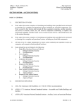
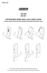
All Verid units have six LEDs to indicate the
status of the unit and guide the individual
through the verification process (see
diagram). In the standard configuration all
the LEDs are controlled by the Verid unit, but
an option is available for the tristate
Go/NoGo LED to be controlled by the host
system.
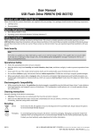
The external system controls the LED with
two lines which are driven by 5V logic
levels:5.0V
High 2V - 5V
HIGH
Low
0V - 1.6V
2.0V
Inputs are high
impedance with
100kΩ pull up
resistors.
Term
3
Low
High
Network functions
Power up – LED “show”
User Interface
When the unit is powered up, the LEDs will
initially cycle through a sequence to
determine the network and configuration
status. This is described in detail in the
Verid User Manual. Once completed, some
of the LEDs may stay illuminated, to indicate
network status. The LEDs will be cleared
once the first PIN is received.
Number of users
Each Verid unit can store templates on up to
5000 users. Each of the 5000 users can
have either one or two fingers registered.
1.6V
Terminal 2
Low
High
Amber
Red
Green
Off
LED control connections:
Security Levels - Verid
Each Verid unit can be set into one of 7
security levels:
“Levels 1 to 5 (strictest)” check the
fingerprint to differing degrees of accuracy.
Additionally, Verid can be set to “PIN only”
(i.e. no fingerprint checking) and “Any
fingerprint” (i.e. the user places a finger on
the unit which is then apparently checked,
but will always pass).
{ Green - match OK
{ Flash red - match failed
“Global setting”: The user will adopt the
security setting of the Verid unit.
Power on
“Levels 1 to 5 (strictest)” check the
fingerprint to differing degrees of accuracy.
Enrollment units also have an LCD display
and four keys to enable selection of the
appropriate function during the enrollment
process. The LCD display can be
programmed via the RS232 port using Verid
Manager to display alternative languages,
including languages requiring double byte
character sets.
•
Network address information will be
resolved by the Verid units on the
network to avoid duplicate network IDs.
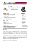
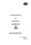
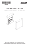
Fixing Details
Attach the backplate to the wall using the
four fixing holes provided (see diagram).
Note a gap of 3mm must be left between
the fixing plate and any adjacent object to
accommodate the housing. Connect all
system wiring to the screw terminals before
diam 5mm
“Any fingerprint” and “PIN Input Only” can
also be assigned to the user.
A user’s individual security level will
override the global level set on the Verid
unit being used.
9.0
Processing data
Remove finger
Any new units added to the network will
adopt the configuration (e.g. PIN device
and messages) of the other units on
the network.
Security Levels - Users
During the enrollment of each user (and
SuperUser), a security level can be assigned
to that user. The levels that can be assigned
to that user are:
Hold finger in position
•
155.0
Place finger - press harder
Any users added, deleted or updated
will immediately be broadcast to all
other Verid units on the network.
109.0
0V
terminal 1
line 1 terminal 2
line 2 terminal 3
•
Installation
LOW
0.0V
If a network of Verid units is set up, the
following tasks will take place automatically
– normally without any PC or user
intervention:
8.6
153.6
162.1
All dimensions in mm
connecting the ribbon cable from the Verid
unit to the terminal plate. Insert the top of
the housing over the back plate and fasten
using the two bolts on the base of the unit.
For maximum security we recommend the
use of anti-tamper bolts (size M4 (metric)).
Installation
All connections are made via the interface PCB mounted on the rear plate:
Terminal No
Terminal No.
1
0V (for LED control)
18
Power supply input: 0V
2
Input - LED1 control
19
Power supply input: +12V
3
Input - LED2 control
20
Output to external device: 0V
21
Output to external device: +5V
4
0V
22
Output to external device: +12V
5
Reserved
6
Reserved
23
0V (for PIN inputs)
7
RS485 – B
24
Input from PIN - Strobe or Wiegand ‘0’
8
RS485 - A
25
Input from PIN - Data or Wiegand ‘1’
26
Input from PIN – CardPresent
9
0V (for Keypad)
27
Input from PIN – TimeOut
10
Keypad column 0
28
Track 3 fingerprint template - Strobe
11
Keypad column 1
29
Track 3 fingerprint template - Data
12
Keypad column 2
13
Keypad column 3
30
0V (for door controller)
14
Keypad row 0
31
Output to door controller - Strobe or Wiegand ‘0’
15
Keypad row 1
32
Output to door controller - Data or Wiegand ‘1’
16
Keypad row 2
33
Output to door controller - CardPresent
17
Keypad row 3
34
Output to door controller - TimeOut
Specifications
Case Details:
Verid is designed so as to comply with
UL294. Verid complies with the following
EMC requirements:
Europe
Height:
160mm
Width:
165mm
Depth:
65mm
Weight:
1 kg
EN55022 Emissions (class A)
EN50082-1 Immunity (class A)
Maintenance
Verid is essentially maintenance free but
will benefit from periodic cleaning of the
optics and housing. Clean the finger platen
with a soft linen free cloth. The housing
may be cleaned with a soft cloth and nonabrasive liquid detergent.
Warning: this is a “Class A” product. In a domestic
environment this product may cause radio
interference in which case the user may be required
to take adequate measures.
Temperature
Operation
0oC to 40oC
Storage
-10oC to 50oC
o
Humidity range @ 40 C
10% to 80% (noncondensing )
Power Requirements:
10V to 14V
500mA max
In order to meet the requirements of EN60950
Verid should be powered from an SELV supply.
North America
FCC rules CFR47 part 15 limit A
Verid has been tested and found to comply with the
limits for a Class A digital device, pursuant to part
15 of the FCC rules. These limits are designed to
provide reasonable protection against harmful
interference when the equipment is used in a
commercial environment. This equipment generates,
uses and can radiate radio frequency energy and, if
not installed and used in accordance with the
instruction manual, may cause harmful interference
to radio communications. Operation of this
equipment in a residential area is likely to cause
harmful interference in which case the user will be
required to correct the interference at his own
expense.
TSSI
Rutland House
Hargreaves Road
Groundwell Industrial Estate
Swindon
Wiltshire SN2 5AZ
U.K.
Telephone:
Facsimile:
e:mail
web:
+44 1793 747700
+44 1793 747701
[email protected]
www.tssi.co.uk
Verid is a trademark of TSSI
Reference: vfu/02
A Scipher Company