1
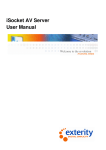
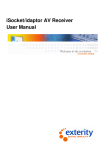
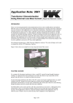
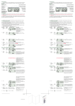
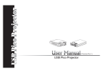
SLM Developer System Liquid Crystal Spatial Light Modulator and dual head PC system for smart optics developers Modulator Features Applications • High spatial resolution - SXGA (1280 x 1024 pixels) • Very high fill factor (93%) • Ferroelectric Liquid Crystal on Silicon (FLCOS) technology • Fast frame rate (kHz) • Configurable for binary amplitude or phase modulation • PURE binary phase modulation • Separate interface electronics with flexible connecting cable • Lightweight and portable SLM module System Features • PC with Linux operating system, pre-installed and configured • Dual head video card • Separate PC monitor and SLM control • Digital Video Interface (DVI) • ‘C’ programming environment • Includes ‘C’ compiler • Programs available for dual head operation with source code • Re-configurable / programmable diffraction patterns • Custom Addressing Sequences • Optical Correlators • Printing • Laser beam steering • Materials processing • Micro-machining • Optical Tweezers • Optical Metrology • Adaptive & Diffractive Optics • Re-configurable Holograms • Holographic displays • Medical imaging • Microscopy • Ophthalmic Equipment • Real-time beam shaping • Wave front manipulation • Free-space optical switching (telecomms) Description The SLM Developer System provides a versatile means of incorporating a spatial light modulator (SLM) in to a variety of applications. The kit can be used to provide amplitude modulation, for example in printing, or phase modulation, say in beam steering. In non-display applications needing a controllable diffractive optical element, CRL Opto’s proprietary FLC based technology is uniquely suited as it can be configured to give pure binary phase modulation without any amplitude artefacts. The fast switching FLC enables applications where speed is important; the compact SLM module allows easy positioning of this high-resolution device where space is limited. A time saving and cost effective solution, the SLM Developer System is supplied to end-users as an instant plug and play unit, designed to significantly reduce integration time. A dual head system allows the user to run control software on the PC and to easily manage the fast data flow to the SLM through the second video interface; importantly, the control interface is displayed on the monitor screen independently of the data image supplied to the slave SLM. The PC is Linux based, as this operating system is well suited to running two independent video channels and avoids the problems often associated with other operating systems. Example dual head programs and source code are provided to allow users to develop their own systems. CRL Opto Limited, 2003 SLM Developer System Datasheet. For further information please contact the CRL Opto Limited Sales department Tel: +44 (0) 20 8848 6421 Fax: +44 (0) 20 8848 6653 Email: [email protected] http://www.crlopto.com Page 1 General Configuration The SLM Developer’s kit consists of a plug and play solution. A PC that is connected to a monitor and a set of interface electronics; the interface electronics drive down a cable to an LVDS receiver that is connected to the SLM by a short flexi connector. The SLM can be mounted on a mechanical mount for fixing and alignment. The system configuration is shown below. PC VESA Monitor Linux based Dual Head video card DVI Interface Electronics 2.5m Cable SLM mount Flexi-Carrier Mounted SXGA SLM SLM Features LVDS Receiver PCB The SLM is a digital Liquid Crystal On Silicon (LCOS) device based on a 0.3um CMOS process. The silicon backplane forms a 1280 × 1024 active pixel plane for the LCD. The liquid crystal cell is constructed on top of the backplane using fast switching Ferroelectric LC with a sub micron cell gap. The SLM is mounted on a flexi-rigid circuit and driven by a small LVDS Receiver (Rxr) PCB. The SLM module and LVDS Rxr PCB are connected to the main interface electronics via a 2.5m connecting cable. The main interface electronics accepts SXGA VESA standard graphics input in DVI formats and generates the addressing sequence and control signals for the SLM. Binary input images can be supplied as single bit colour or as pre-formatted 24-bit colour frames. The data for the SLM is transmitted to the LVDS Rxr PCB via the 2.5m connecting cable The PC is supplied with Control software (including C source code) that provides a Graphical User Interface (GUI), allowing the user to control the current image on the SLM in one window, whilst controlling other aspects of the system from other windows. The user is also able to access SLM configuration data in the interface electronics, to change addressing sequences and to flip the image horizontally/vertically through a configuration utility. On starting up an icon on the desktop, the computer will cycle through some pre-prepared diffractive gratings. A second version of this software allows the user to display or cycle through images that they create and save in the standard portable bitmap format. We will provide the source code for these programs, and the compilers and libraries that will allow the user to adapt the code for their own requirements. Also provided are other sample programs that address the SLM directly from a C program (for example calculating a grating that will steer a beam to a specified position). CRL Opto also offers custom development of addressing sequences for specific applications. CRL Opto Limited, 2003 SLM Developer System Datasheet. For further information please contact the CRL Opto Limited Sales department Tel: +44 (0) 20 8848 6421 Fax: +44 (0) 20 8848 6653 Email: [email protected] http://www.crlopto.com Page 2 1. SXGA SLM Module and LVDS Receiver PCB CRL Opto Limited, 2003 SLM Developer System Datasheet. For further information please contact the CRL Opto Limited Sales department Tel: +44 (0) 20 8848 6421 Fax: +44 (0) 20 8848 6653 Email: [email protected] http://www.crlopto.com Page 3 2. SLM Electronics Unit SLM and Interface Electronics Specification SLM Type Spatial resolution Active area Pixel pitch Fill factor / Aperture Ratio Reflectivity (amplitude modulation) Optical efficiency (phase modulation) Modulation mode Operating temperature range Storage temperature range Interface Electronics Input format SLM cable Repetition rate Interface Module dimensions CRL Opto Limited, 2003 FLCOS, reflective mode 1280 (H) by 1024 (V) pixels 17.43mm (H) x 13.95mm (V) 13.62µm (H) x 13.62µm (V) 93% >70% (including backplane, ITO and cover glass losses) >10% in to combined first diffractive orders in visible Enhanced efficiency and custom wavelengths available. Binary amplitude OR binary phase (0 or π) +10°C to +60°C -40°C to +85°C Digital (DVI) VESA standard graphics, SXGA 60Hz Low voltage differential signalling cable (LVDS). Light weight, flexible cable, 2.5m long (standard). Shorter or longer custom cables are available on request. Up to 1440 Hz Approx. 170mm x 130mm x 55mm SLM Developer System Datasheet. For further information please contact the CRL Opto Limited Sales department Tel: +44 (0) 20 8848 6421 Fax: +44 (0) 20 8848 6653 Email: [email protected] http://www.crlopto.com Page 4 Specification of PC and Control Software PC Make/Model Up to date PC from major manufacturer. capacity, flat screen monitor >250kb RAM, >20Gb hard disc Graphics Card Compatible Dual head video card (SXGA 60Hz) Supply voltage range 120-240V Optional Outputs Synchronisation signal from interface box Software Operating System Linux (Mandrake 8.2 or later version) Control software OpenGL based, gcc compiler SLM config utility (SXProg) GUI software provides control Image flip (left-right and top-bottom invert) and a soft system reset. The GUI also enables different SLM display sequences to be loaded up and updates of ASIC (SLM driver) microcode to be installed. Product Ordering To place an order please quote: Product Configuration SLM Developer System consisting of : A mounting bracket; 1 off SXGA resolution reflective SLM; LVDS Receiver PCB; connected via 2.5m LVDS cable to Interface Electronics module; PC with dual head video card, installed with Linux operating system; C based control software and SLM configuration utility, programming pack, example dual head programs, source code, and User’s Manual on CD ROM. Optional Accessories CRLCMAX CRLCMOX CRLCMEX Mains cable - USA Mains cable – UK Mains cable - Europe Custom lengths of LVDS connecting cable between 0.5 and 5 metres Custom wavelength and diffraction efficiency optimisation Standard 6 mm or ¼” mounting posts to allow easy mounting into existing optical systems If you wish more information, including further advice on how to use our SLMs in your application, please visit our web site http://www.crlopto.com or contact CRL Opto directly: [email protected] CRL Opto Limited, 2003. SLM Developer System Datasheet. CRL Opto doc # 409/0295/01A Page 5 All performance figures and other data contained in this document must be confirmed in writing before they become applicable to any tender, order or contract. The Company reserves the right to make alterations or amendments to the information in this document and/or product specifications at its discretion. No freedom to use patents or other intellectual property rights is implied by the publication of this document. CRL Opto Limited Registered Office: 1 St.David’s Drive, St. David’s Business Park, Dalgety Bay, Fife, KY11 9PF, Scotland. N°: SC174872. A Scipher company For further information please contact the CRL Opto Limited Sales department Tel: +44 (0) 20 8848 6400 Fax: +44 (0) 20 8848 6653 Email: [email protected] Http://www.crlopto.com