1
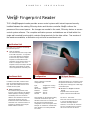
All Verid units have six LEDs to indicate the
status of the unit and guide the individual
through the verification process (see
diagram). In the standard configuration all
the LEDs are controlled by the Verid unit, but
an option is available for the tristate
Go/NoGo LED to be controlled by the host
system.
The external system controls the LED with
two lines which are driven by 5V logic
levels:5.0V
High 2V - 5V
HIGH
Low
0V - 1.6V
2.0V
Inputs are high
impedance with
100kΩ pull up
resistors.
Term
3
Low
High
Network functions
Power up – LED “show”
User Interface
When the unit is powered up, the LEDs will
initially cycle through a sequence to
determine the network and configuration
status. This is described in detail in the
Verid User Manual. Once completed, some
of the LEDs may stay illuminated, to indicate
network status. The LEDs will be cleared
once the first PIN is received.
Number of users
Each Verid unit can store templates on up to
5000 users. Each of the 5000 users can
have either one or two fingers registered.
1.6V
Terminal 2
Low
High
Amber
Red
Green
Off
LED control connections:
Security Levels - Verid
Each Verid unit can be set into one of 7
security levels:
“Levels 1 to 5 (strictest)” check the
fingerprint to differing degrees of accuracy.
Additionally, Verid can be set to “PIN only”
(i.e. no fingerprint checking) and “Any
fingerprint” (i.e. the user places a finger on
the unit which is then apparently checked,
but will always pass).
{ Green - match OK
{ Flash red - match failed
“Global setting”: The user will adopt the
security setting of the Verid unit.
Power on
“Levels 1 to 5 (strictest)” check the
fingerprint to differing degrees of accuracy.
Enrollment units also have an LCD display
and four keys to enable selection of the
appropriate function during the enrollment
process. The LCD display can be
programmed via the RS232 port using Verid
Manager to display alternative languages,
including languages requiring double byte
character sets.
•
Network address information will be
resolved by the Verid units on the
network to avoid duplicate network IDs.
Fixing Details
Attach the backplate to the wall using the
four fixing holes provided (see diagram).
Note a gap of 3mm must be left between
the fixing plate and any adjacent object to
accommodate the housing. Connect all
system wiring to the screw terminals before
diam 5mm
“Any fingerprint” and “PIN Input Only” can
also be assigned to the user.
A user’s individual security level will
override the global level set on the Verid
unit being used.
9.0
Processing data
Remove finger
Any new units added to the network will
adopt the configuration (e.g. PIN device
and messages) of the other units on
the network.
Security Levels - Users
During the enrollment of each user (and
SuperUser), a security level can be assigned
to that user. The levels that can be assigned
to that user are:
Hold finger in position
•
155.0
Place finger - press harder
Any users added, deleted or updated
will immediately be broadcast to all
other Verid units on the network.
109.0
0V
terminal 1
line 1 terminal 2
line 2 terminal 3
•
Installation
LOW
0.0V
If a network of Verid units is set up, the
following tasks will take place automatically
– normally without any PC or user
intervention:
8.6
153.6
162.1
All dimensions in mm
connecting the ribbon cable from the Verid
unit to the terminal plate. Insert the top of
the housing over the back plate and fasten
using the two bolts on the base of the unit.
For maximum security we recommend the
use of anti-tamper bolts (size M4 (metric)).