1
Virtual instrument as desired, iv) the signal conditioning hardware to condition and isolate the
signals before being connected to the DAQ board, and finally, v) the computer, a IBM 486 PC to
house the DAQ board and the LabVIEW and NIDAQ software. In the sections, which follow, the
methodology of the development is presented, followed by the description of the components.
METHODOLOGY
The acquisition of data from a practical system and its display on the computer screen for
study and analysis requires a proper setup of the hardware and software tools involved and a
proper communication between the two. The NIDAQ board communicates to the outside world
through a ribbon cable with terminations on both the DAQ board and the signal conditioner. The
signal conditioner serves as the junction where the conditioned signals are connected to the
channels of the DAQ board. The rest is the set up of the NIDAQ to inform LabVIEW about the
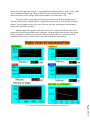
configuration utilized. The front panel, which contains the display features, and the block
diagram, which contains the mechanics on what is being actually displayed constitute the
essential components of LabVIEW. A match of the front panel and block diagrams of the
LabVIEW software delivers the user with a clear understanding of the key procedures involved
and the programming involved. The following describes the details of the components and the
development of the system.
DATA ACQUISITION BOARD AND CONFIGURATION SOFTWARE
The ATMIO-16-DE-10 DAQ board utilized belongs to the family of enhanced multiplefunction input/output boards [8, 9]. It has digital as well as analog input/output capabilities. It has
a total of 16 analog input channels, which can be used in, single ended and differential modes, all
software selectable. All 16 channels can be used in single ended mode only if all the signals have
a common ground. Otherwise, only eight analog input channels are available. In the differential
mode, input voltage range is 0v to 1v. It has two twelve bit analog output channels, whose output
range is -5v to +5v or from 0v to 10v, software selectable, with a current of -5mA to +5mA. The
sampling rate is 100 ksamples/sec. There are, a total of thirty-two digital input/output channels.
It is also equipped with 24-bit, 20 MHz counter/timers. Digital channels are compatible with
TTL/CMOS. The hardware configuration of the DAQ board was studied and the required
channels were configured for this application. The corresponding gains and input voltages were
selected.
SIGNAL CONDITIONER (SCX)
Signal conditioning is necessary to step down the voltages or to shield the signals from
noise and distortion. The actual voltage and current measured have to be stepped down and
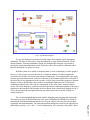
isolated to protect the board. The circuit diagram of the conditioning circuitry, thus developed is
shown in Fig. 2. The maximum generated voltage was 125v. The voltage divider was used to
obtain 1v across the 440k resistor. As the generator voltage varies from 0 to 125v, the voltage
across 440k varies from 0v to 1v. The two 63mA fuses protect the board against any large
currents due to high voltage.
3
Page 3.387.3
Without the availability of other current sensing devices, in order to get a reference
voltage for the current, a variable resistor was used in series with the load. The resistor was