1
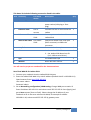
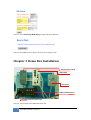
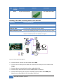
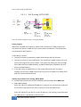
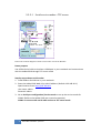
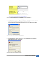
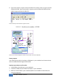
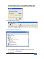
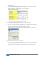
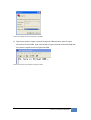
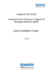
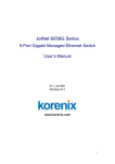
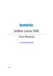
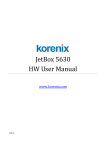
JetBox 9310 User Manual
Demo Box
www.korenix.com
0.0.9
Copyright Notice
Copyright© 2008 Korenix Technology Co., Ltd.
All rights reserved.
Reproduction without permission is prohibited.
Information provided in this manual is intended to be accurate and reliable. However,
the original manufacturer assumes no responsibility for its use, or for any
infringements upon the rights of third parties that may result from its use.
The material in this document is for product information only and is subject to
change without notice. While reasonable efforts have been made in the preparation
of this document to assure its accuracy, Korenix assumes no liabilities resulting from
errors or omissions in this document, or from the use of the information contained
herein.
Korenix reserves the right to make changes in the product design without notice to
its users.
Acknowledgments
Korenix is a registered trademark of Korenix Technology Co., Ltd.
All other trademarks or registered marks in the manual belong to their respective
manufacturers.
2
Overview | Korenix
Table of Content
Copyright Notice ........................................................................................ 2
Acknowledgments ...................................................................................... 2
Table of Content ........................................................................................................ 3
Chapter 1
Overview ............................................................................................ 4
Chapter 2
Package List ........................................................................................ 4
2-1
Standard Demo kit.............................................................................. 4
Chapter 3
Demo Box Installation ........................................................................ 6
3-1
Demo Box Wiring ............................................................................... 7
3-2
Demo Processes ................................................................................. 9
3-2-1
PoE and WAN Related ................................................................. 9
3-2-1-1 PoE, Routing, NAT & DMZ.................................................. 10
3-2-2
Other Functions ........................................................................ 11
3-2-2-1 Serial service modes—TCP server ..................................... 12
3-2-2-2 Serial service modes—VCOM ............................................ 14
3-2-2-3 DIO Control & Web UI ....................................................... 18
Chapter 4
Appendix .......................................................................................... 19
4-1
Index for Picture, Notice ................................................................... 19
4-2
Customer Service ............................................................................. 21
Korenix | Overview
3
Chapter 1 Overview
Korenix Demo Kit is designed to demonstrate Korenix products. In order to let
customers understand Korenix product’s features and applications, Korenix produces
this portable demo box. In the Demo box, Korenix presents the best results, and
impresses customers with product introduction as well as live demonstration.
Chapter 2 Package List
2-1
Standard Demo kit
This demo kit includes following items listed in the table.
Device
Power input
Setting
JetBox 9310
48V DC
(4 pin terminal
block)
1. The default IP of LAN is 192.168.10.1,
subnet mask 255.255.255.0
2. The default IP of WAN is 192.168.11.1,
subnet mask 255.255.255.0
PoE IP camera
48V DC
(PoE, RJ45
connector)
1. The default IP is 192.168.10.55
2. User name: Admin
3. Password: Admin
48V DC power module
(DR-75-48)
DC input from
demo kit
1. To provide 48V DC power to the JetBox
9310
Serial to USB cable
None
1. Connect the USB port of your
NOTEBOOK and the JetBox 9310 serial
port
2. Need to install the driver in your
NOTEBOOK first
4
Overview | Korenix
This demo kit includes following accessories listed in the table.
Item Accessory
For which
device
Description
Q’ty
1
Power cable
Demo kit
Connect the demo kit and your
power socket (USA plug or Euro
plug)
1
2
Ethernet cable
PoE IP
camera
Connect the PoE IP camera and the
JetBox
1
3
Ethernet cable
the JetBox
9310
Connect your notebook and the
JetBox 9310
1
4
RJ45 to DB9 cable the JetBox
9310
Extend the JetBox 9310 serial port
(RJ45 connector) to DB9 male
connector
1
5
Acrylic base
To sustain the demo plate
2
6
CD
1. the JetBox 9310 CD
2. the JetBox 9310 demo box CD
(incl. USB-to-serial driver)
2
7
QIG
the JetBox 9310 QIG
1
8
Manual
Demo box user manual
1
You still need to prepare a notebook for the demonstrations.
Set a fixed WAN IP for JetBox 9310:
1. Connect your notebook into the JetBox 9310 LAN port
2. Enter the JetBox 9310 Web UI by LAN IP address (Default LAN IP is 192.168.10.1)
Open browser. Enter http://192.168.10.1
User name: admin
Password: admin
3. Go to Networking configuration| WAN setting. Change WAN port to static IP.
Enter IP address 192.168.11.1 and subnet mask 255.255.255.0. Press [Apply] and
go to Save to press [Save to Flash]. Please change the IP address of your
notebook to be in the same subnet with WAN, for example IP address
192.168.11.10, subnet mask 255.255.255.0, gateway none.
Korenix | Package List
5
Picture 1: Go to Networking| WAN setting to apply static IP for WAN port
Picture 2: Go to Save and press [Save to Flash] to save changes in flash
Chapter 3 Demo Box Installation
48V DC power module
JetBox 9310
PoE IP Cam
JetBox 9310 DIO Control
110~240V demo box power input
Picture 3: The overview of the JetBox 9310 demo box
6
Demo Box Installation | Korenix
Picture 4: The front panel of JetBox 9310 DIO control
Notice 1: There is a fuse near the demo box power switch to protect the demo
box from the improper current. The power input for the demo box is 110~240V AC.
Picture 5: The fuse of the demo box
3-1
Demo Box Wiring
Following is the wires with corresponding connectors in this demo box.
Item
1
Output
voltage
48V DC
Connector
4 pin terminal block
Pictures
Connect to
the JetBox 9310
power
Korenix | Demo Box Installation
7
Item
Output
voltage
Connector
2
None
10 pin terminal block
Pictures
Connect to
the JetBox 9310 DIO
Following is the cables connecting devices in this demo box
Accessory
Connected devices
Power cable
Connect the demo kit and your power socket
Ethernet cable
Connect the IP camera and the JetBox
Ethernet cable
Connect your notebook and the JetBox
RJ45 to DB9 male cable
Connect the JetBox 9310 serial port and USB-to-Serial cable
USB to serial cable
Connect the USB of your notebook (to simulate a COM port
of your notebook) and the JetBox serial port
Picture 6: Demo Box wiring diagram
1. Connect PoE IP camera and the JetBox 9310 LAN4
2. Connect Serial cable (RJ45-to-DB9 and USB-to-Serial cables) and the JetBox 9310
COM1
3. Connect 10-pin terminal block and the JetBox 9310 DIO
4. Connect 4-pin terminal block and the JetBox power connector
5. Connect the Ethernet port of your notebook and the JetBox 9310 WAN port
(Need to set a fixed WAN IP for the JetBox 9310 first)
8
Demo Box Installation | Korenix
Notice 2: Please connect power (positive and negative) correctly, otherwise the
devices might be damaged.
Notice 3: While the JetBox 9310 is booting up, the status of all digital outputs are
temporary high.
3-2
Demo Processes
Notice 4: All snapshots are for image reference only, not real settings of demo
processes.
3-2-1 PoE and WAN Related
For WAN related demonstration, you need to set the Ethernet configuration of your
notebook as follows:
IP address: 192.168.11.10 (the same subnet with WAN)
Subnet mask: 255.255.255.0
Gateway: (none)
Connect the Ethernet port of your notebook and the JetBox 9310 WAN port.
The default Web UI setting of JetBox 9310 for WAN related demonstrations is as
follows:
Networking configuration| NAT setting
Masquerade enable
DMZ enable
Server IP 192.168.10.55 (the IP address of the PoE IP camera)
Korenix | Demo Box Installation
9
Picture 7 NAT setting of JetBox 9310
3-2-1-1 PoE, Routing, NAT & DMZ
Picture 8: The demo diagram of PoE, routing, NAT & DMZ
Demo purpose:
When NAT and DMZ are enabled in JetBox 9310, the devices in WAN network can
only access the server in DMZ and can’t access other LAN devices. The LAN devices
are protected by NAT function.
In this demo, it shows:
1. The PoE IP camera is powered by JetBox 9310 though the PoE function.
2. The PoE IP camera is set as DMZ server. Your notebook in WAN network can only
access the image of the PoE IP camera. This shows the routing (IP camera image
from LAN network to WAN network), and NAT & DMZ (your notebook can only
access the DMZ server).
3. If you did not set any DMZ server in the JetBox 9310 when NAT function is
enabled, the devices in WAN network can only access the Web UI of JetBox 9310
and can’t access the LAN devices.
Step by step to demo PoE, routing, NAT & DMZ:
1. Connect the Ethernet port of your notebook and the JetBox 9310 WAN port
2. Open Web browser.
Enter 192.168.11.1 (JetBox 9310 WAN port), and you can see the frame captured
by the PoE IP cam because the PoE IP camera is set as the DMZ server.
Enter 192.168.10.55 (the PoE IP camera IP address), and nothing is found because
the LAN devices is protected by NAT function.
10
Demo Box Installation | Korenix
The Ethernet configuration of PoE IP cam is set as follows:
IP address: 192.168.10.55 (also set this IP address as DMZ server in JetBox 9310)
Subnet mask: 255.255.255.0
Gateway: 192.168.10.1
Video port: under 1000
Picture 9: The frame captured by the PoE IP camera
3-2-2 Other Functions
For the demonstrations of other functions, you need to set the Ethernet
configuration of your notebook as follows:
IP address: 192.168.10.99 (the same subnet with LAN)
Subnet mask: 255.255.255.0
Gateway: (none)
Connect the Ethernet port of your notebook and the JetBox 9310 LAN1 port.
Korenix | Demo Box Installation
11
3-2-2-1 Serial service modes—TCP server
Picture 10: The demo diagram of serial service mode—TCP server & VCOm
Demo purpose:
Use USB-to-Serial cable to simulate a COM port in your notebook and communicate
with the JetBox 9310 through TCP server mode
Step by step to demo serial modes:
1. Install USB-to-Serial driver in your notebook
2. Enter the JetBox 9310 Web UI by LAN IP address. (Default: 192.168.10.1).
Open browser. Enter http://192.168.10.1
User name: admin
Password: admin
3. Go to Serial port configuration| Service mode to set up the service mode for
COM1. (Refer to the JetBox 9310 user manual to operate.)
COM1: to connect with serial cable and set as TCP server mode
12
Demo Box Installation | Korenix
Picture 11: Serial port configuration| Service mode of the JetBox 9310 Web UI
4. Use hyper terminal (named Physical COM) in your notebook to connect with the
JetBox 9310 through physical COM (often COM1 or COM2)
The physical COM is connected by RJ45-to-DB9 male and USB-to-serial cables.
Picture 12: Hyper terminal connection—Physical COM
5. Use hyper terminal (named COM-TCP) in your notebook to connect with the
JetBox 9310 through TCP server mode.
Picture 13: Hyper terminal connection—TCP/IP
Korenix | Demo Box Installation
13
6. Type some words in hyper terminal of COM-TCP and they show in hyper terminal
of physical COM. Type some words in hyper terminal of physical COM and they
show in hyper terminal of COM-TCP.
Picture 14: Key in some words in hyper terminal
3-2-2-2 Serial service modes—VCOM
Picture 15: The demo diagram of serial service mode—TCP server & VCOm
Demo purpose:
Use USB-to-Serial cable to simulate a COM port in your notebook and communicate
with the JetBox 9310 through VCOM mode.
Step by step to demo serial modes:
1. Install USB-to-Serial driver in your notebook
2. Install the JetBox Virtual COM Commander in your notebook
3. Add one Virtual COM in your notebook (Refer to the JetBox Virtual COM user
manual to operate.)
14
Demo Box Installation | Korenix
For example: COM port number 20, Remote [IP & port] 192.168.10.1, 62004
This is to set a VCOM (COM 20) in your notebook to the JetBox 9310 COM4.
Picture 16: Add a VCOM in your notebook
Picture 17: the JetBox Virtual COM Commander
Picture 18: the JetBox Virtual COM in the device manager
4. Enter the JetBox 9310 Web UI by LAN IP address. (Default: 192.168.10.1).
Open browser. Enter http://192.168.10.1
User name: admin
Korenix | Demo Box Installation
15
Password: admin
5. Go to Serial port configuration| Service mode to set up the service mode for
COM4. (Refer to the JetBox 9310 user manual to operate.)
COM4: set as VCOM mode
Picture 19: Serial port configuration| Service mode of the JetBox 9310 Web UI
6. Use hyper terminal (named Physical COM) in your notebook to connect with the
JetBox 9310 through physical COM (often COM1 or COM2)
The physical COM is connected by RJ45-to-DB9 male and USB-to-serial cables.
Picture 20: Hyper terminal connection—Physical COM
7. Use hyper terminal (named Virtual COM) in your notebook to connect with the
JetBox 9310 through VCOM (for example, COM 20 you set in previous step).
16
Demo Box Installation | Korenix
Picture 21: Hyper terminal connection—VCOM
8. Type some words in hyper terminal of physical COM and they show in hyper
terminal of Virtual COM. Type some words in hyper terminal of Virtual COM and
they show in hyper terminal of physical COM.
Picture 22: Key in some words in hyper terminal
Korenix | Demo Box Installation
17
3-2-2-3 DIO Control & Web UI
Picture 23: The demo diagram of DIO control and Web UI
Notice 5: In this DIO demo, you need to enable DO 0 to provide the power to DIs
first, otherwise, DIs don’t have power to do the demo. Keep DO 0 enabled during this
DIO demonstration.
Demo Purpose:
Control switches and indicators on the demo box front panel though the JetBox 9310
Web UI DIO functions
Step by step to demo DIO control and Web UI:
1. Enter the JetBox 9310 Web UI by LAN IP address. (Default: 192.168.10.1).
Open browser. Enter http://192.168.10.1
User name: admin
Password: admin
2. Control switches and indicators on the demo box front panel though the JetBox
9310 Web UI DIO functions. (Refer to the JetBox 9310 user manual to operate.)
3. Enable or disable indicators (DO) in the JetBox 9310 Web UI| DIO configuration|
Digital output control.
18
Demo Box Installation | Korenix
Picture 24: DIO configuration| Digital output control in the JetBox 9310 Web UI
4. Check the status of switches (DI) in the JetBox 9310 web UI| DIO configuration|
DIO status.
Picture 25: DIO configuration| DIO status in the JetBox 9310 Web UI
Chapter 4 Appendix
4-1
Index for Picture, Notice
Picture
Picture 1: Go to Networking| WAN setting to apply static IP for WAN port 6
Picture 2: Go to Save and press [Save to Flash] to save changes in flash ..... 6
Picture 3: The overview of the JetBox 9310 demo box ............................... 6
Picture 4: The front panel of JetBox 9310 DIO control ................................ 7
Picture 5: The fuse of the demo box ........................................................... 7
Picture 6: Demo Box wiring diagram .......................................................... 8
Picture 7 NAT setting of JetBox 9310 ........................................................ 10
Korenix | Appendix
19
Picture 8: The demo diagram of PoE, routing, NAT & DMZ ....................... 10
Picture 9: The frame captured by the PoE IP camera ................................ 11
Picture 10: The demo diagram of serial service mode—TCP server & VCOm
......................................................................................................... 12
Picture 11: Serial port configuration| Service mode of the JetBox 9310
Web UI ............................................................................................. 13
Picture 12: Hyper terminal connection—Physical COM ............................ 13
Picture 13: Hyper terminal connection—TCP/IP ....................................... 13
Picture 14: Key in some words in hyper terminal ...................................... 14
Picture 15: The demo diagram of serial service mode—TCP server & VCOm
......................................................................................................... 14
Picture 16: Add a VCOM in your notebook ............................................... 15
Picture 17: the JetBox Virtual COM Commander ...................................... 15
Picture 18: the JetBox Virtual COM in the device manager ....................... 15
Picture 19: Serial port configuration| Service mode of the JetBox 9310
Web UI ............................................................................................. 16
Picture 20: Hyper terminal connection—Physical COM ............................ 16
Picture 21: Hyper terminal connection—VCOM ....................................... 17
Picture 22: Key in some words in hyper terminal ...................................... 17
Picture 23: The demo diagram of DIO control and Web UI ....................... 18
Picture 24: DIO configuration| Digital output control in the JetBox 9310
Web UI ............................................................................................. 19
Picture 25: DIO configuration| DIO status in the JetBox 9310 Web UI ..... 19
Notice (Limitation of this demo box)
Notice 1: There is a fuse near the demo box power switch to protect the
demo box from the improper current. The power input for the demo
box is 110~240V AC. .......................................................................... 7
Notice 2: Please connect power (positive and negative) correctly, otherwise
the devices might be damaged. .......................................................... 9
Notice 3: While the JetBox 9310 is booting up, the status of all digital
outputs are temporary high. ............................................................... 9
Notice 4: All snapshots are for image reference only, not real settings of
demo processes.................................................................................. 9
Notice 5: In this DIO demo, you need to enable DO 0 to provide the power
to DIs first, otherwise, DIs don’t have power to do the demo. Keep DO
0 enabled during this DIO demonstration. ........................................ 18
20
Appendix | Korenix
4-2
Customer Service
Korenix Technologies Co., Ltd.
9F, No. 100-1, Ming-Chuan Rd., Shing Tien City, Taipei, Taiwan
Tel:+886-2-82193000 Fax:+886-2-82193300
Business service: [email protected]
Customer service: [email protected]
Korenix | Appendix
21