1
1.2 Hardware
1.2 Hardware:
The Programmer consists of a board, a separate power supply
unit and a serial port cable.
The power supply provides a set of DC voltages like 9V, 500mA
and 18V, 100mA . The programmer board has on board regulators
for generating 5V and 12V required for the normal operation and
programming purposes.
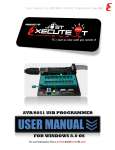
The Programmer board sports a single 40 pin ZIF socket for programming both 40 and 20 pin devices.
A DIN connector marked as ‘POWER’ is used for connecting the
power supply unit to the programmer board The terminations of
the connector is given below:
· Pin 1 & 2 - 9V
· Pin 3 & 4 - Ground
· Pin 6 & 7 - 18V
Similarly the connecter named as ‘SERIAL PORT’ helps to connect the host computer to the programmer board. The serial port
connector details are given below:
·
·
·
·
·
·
·
Pin 1 - NC
Pin 2 - RXD
Pin 3 - TXD
Pin 4 - NC
Pin 5 - Ground
Pin 6 - NC
Pin 7 - NC
Atmel 89CXX Flash Programmer
3