Transcript
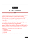
SLC Gauge User Manual
Warning
•
•
•
•
•
SLC Gauge is designed for Gasoline fuel only.
Lambda Sensor gets very hot during normal operation, be careful when handling it.
Do not install Lambda Sensor in such a manner that the unit is powered before your engine is running. An engine start can move
condensation in your exhaust system to the sensor, if the sensor is already heated this can cause thermal shock and cause the
ceramic internals inside the sensor to crack and deform.
While the Lambda Sensor is in an active exhaust stream, it must be powered. Carbon from an active exhaust can easily build up
on an unpowered sensor and ruin it.
Lambda sensor life when used with leaded fuels is between 100-500 hrs. The higher the metal content the shorter the life of the
Lambda sensor.
Package Contents
1x SLC Gauge, 1x Metal bracket, 2x washer, 2x nut, 2x bolt, 1x Combination cable; sensor+power+input+outputs, 1x O2 Bung
Exhaust Installation
•
•
Lambda Sensor should be installed between the 10 o’clock and the 2 o’clock position, less than 60 degrees from vertical, this will
allow gravity to remove water condensation from the sensor.
For all Oxygen sensor installations the sensor must be installed before the catalytic converter.
For normally aspirated engines the sensor should be installed about 2ft
from the engine exhaust port. For Turbocharged engines the sensor should
be installed about 3ft from the engine exhaust port after the turbocharger.
For Supercharged engines the sensor should be installed 3ft from the
engine exhaust port. Installing the sensor too close to the engine exhaust
port may overheat the sensor, installing the sensor too far from the exhaust
port may leave the sensor too cool, both will cause damage to the sensor
and lead to wrong measurements.
Wiring
If you plan on using SLC Gauge as just a visual display of Air to Fuel ratios
•
Only Red, Black, and Blue wires need to be connected
•
The Black and Blue wires can be grounded at the same location
If you plan on interfacing the Linear Output to a device such as an ECU or datalogger
•
Black wire should be grounded where interfacing device is grounded
•
Blue wire should be grounded to engine block or chassis
Wire Color
Red
Black
Blue
Yellow
White
Orange
Name
Power
Electronics Ground
Heater Ground
Linear Output
Simulated Narrowband Output
Dim
Connects to
Switched 12[v]
Ground
Ground
ECU/Datalogger/etc… if required
ECU if required
Headlight Power
Note
12[v] should be live only when engine is running
Ground
Ground
0[v] @ 10[AFR] Linear to 5[v] @ 20[AFR] for gasoline
Switch point @ 14.7[AFR] for gasoline fuel
Half brightness when @ 12[v], full brightness when <
12[v]. Leave disconnected if night dimming is not
required.
Warranty
14Point7 warrants SLC Gauge to be free from defects for 2 years. Sensors if purchased from 14Point7 carry no warranty whatsoever. Warranty
does not cover user error and abuse.
Disclaimer
14Point7 is liable for damages only up to the purchase price of its products. 14Point7 products should not be used on public roads.