1
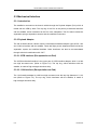
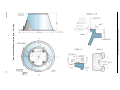
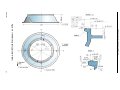
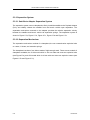
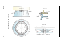
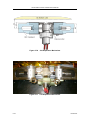
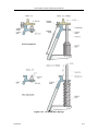
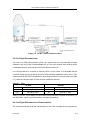
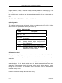
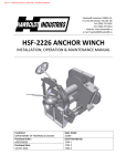
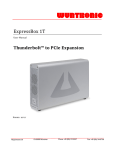
LM-3A Series Launch Vehicle User’s Manual CHAPTER 5 MECHANICAL AND ELECTRICAL INTERFACES 5.1 Introduction This Chapter defines the mechanical and electrical interfaces between the satellite and the LM-3A Series launch vehicles. The mechanical interface is to mate the satellite with the launch vehicle via the Payload Adapter (PLA). The electrical interface electrically connects the satellite with launch vehicle and satellite ground support equipment. 5.2 Satellite Reference Axes The satellite coordinate system shall be aligned with the coordinate system of the LM-3A Series launch vehicle as shown in Figure 5-1. Figure 5-1 Issue 2011 LM-3A Series Launch Vehicle Coordinate System 5-1 LM-3A Series Launch Vehicle User’s Manual 5.3 Mechanical Interface 5.3.1 Introduction The satellite is mounted on the launch vehicle through the Payload Adapter (PLA) which is mated with the VEB by bolts. The top ring of the PLA is the primary mechanical interface with the satellite, which is attached to the PLA via a clampband. The PLA also includes the separation springs, separation sensors and the umbilical connectors. 5.3.2 Payload Adapter The LM-3A Series launch vehicle uses the international standard adapter types 937B, 1194 and 1194A to interface with the satellite. These are flight proven adapters and all include the separation system and umbilical brackets. Other interfaces can also be accommodated through technical coordination with CALT. 5.3.2.1 937B Interface (Encapsulation-on-Pad) The 937B mechanical interface is the upper part of 937B interface adapter, which is a 900 mm high truncated cone. (Refer to Figure 5-2). The top ring, which interfaces with the satellite, is made of high-strength aluminum alloy. 5.3.2.2 1194 Interface (Encapsulation-on-Pad) The 1194 interface adapter is a 650 mm high truncated cone with top ring diameter of 1,215 mm (Refer to Figure 5-3). The top ring, which interfaces with the satellite, is made of high-strength aluminum alloy. 5-2 Issue 2011 Issue 2011 937B Interface (Encapsulation-on-Pad) LM-3A Series Launch Vehicle User’s Manual Figure 5-2 5-3 5-4 1194 Interface (Encapsulation-on-Pad) LM-3A Series Launch Vehicle User’s Manual Figure 5-3 Issue 2011 LM-3A Series Launch Vehicle User’s Manual 5.3.2.3 1194A Interface (Encapsulation-on-Pad) The 1194A adapter for Encapsulation-on-Pad is a 650 mm high truncated cone (see Figure 5-4 and Figure 5-5). Figure 5-4 Payload Adapter with 1194A Interface 5.3.2.4 1194A interface (Encapsulation-in-BS3) The 1194A adapter for encapsulation in BS3 is a 450 mm high truncated cone (see Figure 5-6). Issue 2011 5-5 5-6 1194A Interface (Encapsulation-on-Pad) LM-3A Series Launch Vehicle User’s Manual Figure 5-5 Issue 2011 Issue 2011 1194A Interface (Encapsulation-in-BS3) LM-3A Series Launch Vehicle User’s Manual Figure 5-6 5-7 LM-3A Series Launch Vehicle User’s Manual 5.3.3 Separation System 5.3.3.1 Satellite to Adapter Separation System The separation system uses a clampband to firmly install the satellite to the Payload Adapter (PLA) and reliably release the satellite from the launch vehicle upon separation. The separation mechanism mounted on the adapter provides the relative separation velocity between the satellite and launch vehicle via separation springs. The separation system is shown in Figure 5-7a, Figure 5-7-b, Figure 5-7c, Figure 5-7d and Figure 5-7e. 5.3.3.2 Separation Mechanism The separation mechanism consists of a clampband, the non-contamination explosive bolts or cutters, V-shoes, and retention springs. The clampband consists of two halves made of high-strength steel. There are two models of clampband available, the C100 model which is 100 mm wide and uses two explosive bolts (see Figure5-7a), and C60 model which is 60 mm wide and uses two explosive cutters (see Figures 5-7b and Figure 5-7c). 5-8 Issue 2011 Issue 2011 C100 Separation Mechanism LM-3A Series Launch Vehicle User’s Manual Figure 5-7a 5-9 LM-3A Series Launch Vehicle User’s Manual 5-10 Figure 5-7b C60 Separation Mechanism Figure 5-7c C60 Separation Mechanism Issue 2011 LM-3A Series Launch Vehicle User’s Manual Figure 5-7d Issue 2011 SC Separation Springs 5-11 LM-3A Series Launch Vehicle User’s Manual Figure 5-7e 1194/1194A Clampband The non-contamination explosive bolts and explosive cutters are fully redundant with each bolt or cutter having two igniters. The maximum allowable tension force for cutters is 45 kN, and for the explosive bolt the margin is much greater. The V-shoes, which are made of high strength aluminum, are used for clamping the interface ring of the satellite to the top ring of the Payload Adapter (PLA). The lateral-restraining springs are used for restraining the outward movement of the clampband and the longitudinal-restraining springs restrict the movement of the clampband toward the satellite after clampband release. The two halves of the clampband are therefore restrained to the PLA below the separation plane to avoid re-contact. The separation spring assembly is mounted on the PLA providing a separation velocity of 0.5 m/s or greater, and can also provide a lateral axis spin rate of less than 3.0 deg/s, the spin rate being dependent on the customer’s requirement. 5.3.3.3 Installation Requirements During the installation of the clampband system, 10 strain gauges are installed on each half 5-12 Issue 2011 LM-3A Series Launch Vehicle User’s Manual of the clampband so that the strain and pretension at each measuring point can be monitored in real time. A special purpose tool is used to apply the pretension, which is normally in the range of 24~30 kN. The pretension can, however, be adjusted to meet the specific requirements of the satellite and the results of the coupled load analysis. For both C100 and C60 clampband, a minimum clearance of ≥ 85 mm for C100 and ≥ 60 mm for C60 is required between the lowest point on the satellite and the separation plane after installation. If that cannot be achieved, there should be a minimum clearance of ≥ 20 mm between the lateral-restraining springs and the lowest point on the satellite. 5.4 Electrical Interfaces 5.4.1 Summary CLTC and CALT provide the RF link and the umbilical link between the satellite and the satellite Electrical Ground Support Equipment (EGSE) after the satellite is mated with launch vehicle. These links allow the customer to conduct pre-launch testing and monitor the satellite during the launch count down. The schematic of the umbilical cable and RF links between the satellite and the EGSE is shown in Figure 5-8 and Figure 5-9. The umbilical cable is designed and manufactured by CALT to meet the requirements of the customer based on their satellite platform. The 350 m cable from FER to the Umbilical Tower, and the hardware labeled EB26/EB36, BOX3 and Power-supply 1&2 are common to all missions. The umbilical cable integral to the launch vehicle plus the ground facility cable from WXTC to ED10, ED12, ED13, ED14, BOX1 and BOX2, will be designed specifically for customer. Issue 2011 5-13 LM-3A Series Launch Vehicle User’s Manual Figure 5-8 5-14 SC Umbilical Cable Configuration Issue 2011 LM-3A Series Launch Vehicle User’s Manual Figure 5-9 SC RF Links & Umbilical Cables 5.4.2 In-Flight-Disconnectors Two sets of In-Flight-Disconnectors (IFDs) are required and are symmetrically mounted outside the top ring of the Payload Adapter (PLA). The exact location and clocking will be coordinated between customer and CALT and defined in the ICD. It is normal practice for customer to select the IFDs. In such cases, it is advisable that the customer supply the launch vehicle portion of IFDs including installation tools to CALT. IFDs manufactured by DEUTSCH Engineered Connecting Devices are recommended (see Table 5-1), while the Chinese made YF8-64 are also available if selected. Table 5-1 IFDs LV Side SC Side Code Type Code Type P01 D8179E37-OPN J01 D8174E37-OSN P02 D8179E37-OPY J02 D8174E37-OSY Notes: The IFDs will be totally disconnected when the two halves have separated from each other by 13.5 mm. The customer can also select other products by Deutsch as required, e.g. the DBAS7061, which is manufactured by cold-press processing. 5.4.3 In-Flight-Disconnectors Characteristics The customer shall specify all the characteristics of the IFDs, including the pin assignments, Issue 2011 5-15 LM-3A Series Launch Vehicle User’s Manual usage, maximum voltage, maximum current, one-way maximum resistance, type and pin-assignment of connectors to be mated with the ground equipment, etc. CALT will design the umbilical cable according to the above requirements, which will also be defined in the ICD. 5.4.4 Umbilical Cable Onboard Launch Vehicle (a) Configuration The umbilical cables onboard the launch vehicle are cables from the IFDs (P01, P02) to WXTC, which will fly with launch vehicle (See Table 5-2). Table 5-2 Umbilical Cable Code P01, P02 EC1, EC2 EY1 WXTC G1 Description IFD Mechanical technological interfaces between PLA and LV Interface between umbilical cable and LV TM system, through which the SC/LV IFD (J01/P01, J02/P02) separation signal is sent to LV TM system Umbilical cable connector (type: JF5-231) Grounding points to connect the shielding of the wires to the shell of the LV (b) Separation Signal The separation signal is generated through break-wires on the IFDs P01 & P02. The satellite will receive the separation signals once the break-wires are disconnected upon separation. In addition, there are another two break-wires on the IFDs J01 & J02 that will generate the separation signal for the launch vehicle once the break-wires are disconnected upon separation. This separation signal will be sent to the launch vehicle telemetry system through the EY1 interface. The break-wires allow a maximum current of 100 mA and a maximum voltage of 30 V. Figure 5-10 shows an example the break-wire circuitry. 5-16 Issue 2011 LM-3A Series Launch Vehicle User’s Manual Figure 5-10 An Example of Separation Signals & Break-wires There are also two micro-switches on the PLA to give the mechanical separation signal, which is also sent to the launch vehicle telemetry system. 5.4.5 Ground Umbilical Cables (a) Configuration The ground umbilical cables are cables from the WXTC to COTE in the FER which are shown in Figure 5-9, and the functions are shown in Table 5-3. Issue 2011 5-17 LM-3A Series Launch Vehicle User’s Manual Table 5-3 Ground Umbilical Cable Functions Code Description WXTC is the umbilical cable connector (LV-Ground) whose female half (socket) is installed at the VEB, while the male half (pin) is attached to the top end of ground cable. The disconnection of WXTC is electrically controlled. (The disconnection is powered by BOX3. In the mean time, forced disconnection is also used as a back-up separation method.) Generally, WXTC disconnects at about 10 minutes WXTC prior to launch. If the launch was terminated after the disconnection, WXTC could be reconnected within 30 minutes. The SC should switch over to internal power supply and cut off ground power supply at 5 minutes prior to WXTC disconnection. Therefore, during disconnection only a low current monitoring signal (such as 30 V, ≤100 mA) is permitted to pass through the WXTC. BOX1 is a box adapter for the umbilical cable that is located inside the SC Cable BOX1 Measurement Room on floor 8.5 of the umbilical tower. (If needed, BOX1 can provide more interfaces for the connection with SC ground equipment.) BOX2 is another box adapter for the umbilical cable that is located inside the SC BOX2 FER on ground. The SC ground support equipment are also located inside the FER. (b) Ground Interface The customer determines the requirement for the ground interface, but normally there are two ground interfaces for the satellite test console (J11 & J12). The detailed requirements for these ground interfaces shall be jointly agreed by customer and CALT (See Table 5-4). CALT typically prepares short interface cables, so the customer is required to provide the mating half of the connectors (J11 & J12) for the cables that interface with the satellite ground equipment. Table 5-4 Ground Interfaces for Satellite Test Location Code Specification Quantity LV side interfaces J11 J12 To be defined by SC side 2 2 If the customer cannot provide the connectors, there are two options available. CALT can provide the interface cables with each wire labeled with a number in accordance with the pin assignment of the connector for installation into the customer’s connectors when available. The second option is for the customer to manufacture this cable and provide it to CALT, in which case CALT will provide the mating set of connectors for BOX2 in Figure 5-8. The length of this cable is approximately 5 m. 5-18 Issue 2011 LM-3A Series Launch Vehicle User’s Manual 5.4.6 Shielding and Grounding 5.4.6.1 Shielding In order to protect against lightning and stray voltages, the following measures have been implemented: (a) The ground umbilical cable has two shielding layers. The outer shielding is for protection against lightning and the inner shielding is for EMI protection. (b) The ground umbilical cables from WXTC to BOX2 have a grounding point every 20 meters for the outer shielding layer to ensure that any charge buildup from a lightning strike or other inductance can be discharged immediately. (c) After the umbilical connectors are mated, the cable shielding is automatically connected to the launch vehicle shell structure. (d) The inner shield has a single ground. The inner shields of the umbilical cables onboard launch vehicle are connected to BOX2. (e) The inner and outer shields are insulated from each other within the cables. 5.4.6.2 Continuity of Satellite Grounding The satellite shall have a ground reference point close to the separation plane. The resistance between all other metal parts of satellite (shell, structures, etc.) and the reference ground shall be less than 10 m for a current of 10 mA. In order to maintain the continuity of the grounding, the bottom of satellite structure to be mated with the Payload Adapter (PLA) shall not be treated with any protective process that would affect its ability to meet the resistance requirements between the satellite and PLA. 5.5 Satellite Constraints The satellite shall not transmit any remote signal that could be dangerous or interfere with the launch vehicle flight until the satellite has been completely separated from the launch vehicle. The satellite shall not start its automated post separation program until it receives the separation signal from the launch vehicle. 5.6 RF Links Issue 2011 5-19 LM-3A Series Launch Vehicle User’s Manual 5.6.1 RF Relay Path The launch site can provide an RF link between the Satellite Test Equipment (STE) and the SC, whenever the SC is in BS or at the launch pad. The RF link equipment is set up between BS2 and the launch towers. It provides uplink and downlink RF channels that can connect the STE with the SC and transmit the test and control signals when the SC is mated to the launch vehicle at the launch pad. The RF system uses optical fiber to transmit and receive the signals. 5.6.2 Characteristics and Interface of RF Link (a) Frequency The optical fiber of the RF system allows the transmission of 350 MHz to 15 GHz signal, while the microwave processing unit allows the transmission of signals in UHF, L, S, C, Ku and X bands. (b) Signal Level The signal level interface between RF system and STE is shown in Table 5-5. Table 5-5 Signal level interface between RF system and STE SC Antenna Band System Terminal EIRP (dBm) PFD (dBW/m2) Input (dBm) Output (dBm) Uplink -20 ~ 10 / / -50 ~ -80 Downlink / -30 ~ -10 0 ~ 60 / Uplink -20 ~ 10 / / -50 ~ -80 Downlink / -30 ~ -10 0 ~ 60 / UHF Uplink -20 ~ 10 / / -50 ~ -80 X Downlink / -30 ~ -10 0 ~ 60 / L Downlink / -30 ~ -10 0 ~ 60 / Uplink / -20 ~ 10 / -50 ~ -80 Downlink -30 ~ -10 / 30 / S C Ku 5.7 Post Encapsulation Interfaces 5.7.1 Payload Usable Volume The payload usable volume is the area within the fairing that is available to accommodate 5-20 Issue 2011 LM-3A Series Launch Vehicle User’s Manual the satellite when mounted on the Payload Adapter (PLA) of the launch vehicle. This represents the total maximum envelope available for the satellite and includes all manufacturing tolerances, thermal protection, satellite appendages, etc, and also includes the dynamic tolerances based on results of the standard coupled loads analysis. If the satellite has appendages that protrude to outside the usable envelope, they shall be reviewed during the ICD and Mission Reviews. If the protusions are found after these satellite appendages have been completed, a special review shall be held to resolve the issue. 5.7.2 Satellite Access The satellite can be accessed while in the fairing via special access doors on the fairing as agreed in the ICD. The satellite can be accessed up until (Launch – 2 hours) after which time the fairing is sealed. 5.8 Interface Verification 5.8.1 Satellite AIT During the satellite AIT program and prior to final acceptance for delivery to the launch site, a full mechanical and electrical fit check can be performed. This interface verification, or SC/LV fitcheck, is mandatory for all satellite platforms that have not previously been launched with the LM-3A Series launch vehicles. The primary objective of the test is to verify that the mechanical interface is correct, the electrical interfaces are compatible and all the connectors and arming plugs can be accessed. This fitcheck can then be followed by a SC/LV separation shock test to verify if the satellite could be separated from the Payload Adapter (PLA) properly within the required shock level. The SC/LV fitcheck and separation shock test is typically performed at the satellite manufacturers’ facility using the flight adapter and separation system provided by CALT. 5.8.2 Launch Site Interface Verification The electrical and RF interfaces between the satellite and each site for satellite processing, including those where the satellite is mated to the launch vehicle, shall be validated prior to the satellite moving to a new facility and after its arrival at a new facility. This verification is to be performed whenever the umbilical connecters are disconnected and reconnected. Issue 2011 5-21 LM-3A Series Launch Vehicle User’s Manual 5.8.3 Satellite EGSE Interface Verification There are typically two sets of EGSE. One set is permanently located in BS2 that is used as the primary system for controlling the satellite. The second set moves with the satellite and functions as a remote test interface with the satellite. The interfaces of this EGSE shall be verified prior to its arrival at the launch site and following each move at the launch site. The interfaces with the launch site facility are defined in Chapter 7. 5-22 Issue 2011