1
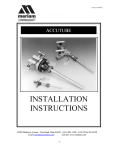
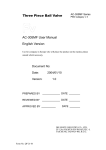
Sample Probe Module AA Swagelok Swagelok®® Pre-Engineered Pre-Engineered Subsystem Subsystem • Pre-engineered subsystems available in weeks, not months. • Field-tested design ensures optimum system performance. User’s Manual 2 Contents Sample Probe Module System Manual . . . . . . . . . . . . . . . 3 Introduction . . . . . . . . . . . . . . . . . . . . . . . . . . . . . 4 Configurations . . . . . . . . . . . . . . . . . . . . . . . . . . . 4 Dimensions . . . . . . . . . . . . . . . . . . . . . . . . . . . . 6 Installation . . . . . . . . . . . . . . . . . . . . . . . . . . . . 10 Operation . . . . . . . . . . . . . . . . . . . . . . . . . . . . . 16 Maintenance . . . . . . . . . . . . . . . . . . . . . . . . . . . . 17 SPV Heater Option . . . . . . . . . . . . . . . . . . . . . . . . 19 SPV Probe Packing Gland Lockout Bracket Option . . . . . . . 23 Troubleshooting . . . . . . . . . . . . . . . . . . . . . . . . . . 25 System Component User Instructions . . . . . . . . . . . . . . . 27 Swagelok Tube Fitting Instructions for 1 in. (25 mm) and smaller fittings, MS-12-01 . . . . . . . . . . . . . . . . . 27 Packing Adjustment for 40G Series Ball Valves, MS-INS-40G . . . . . . . . . . . . . . . . . . . . . . . . . . 28 A Swagelok Pre-Engineered Subsystem Sample Probe Module 3 Sample Probe Module (SPM) System Manual A Swagelok Pre-Engineered Subsystem Sample Probe Module 4 Introduction The Swagelok® Sample Probe Module (SPM) is a pre-engineered solution for use in online process analyzers, that consists of a welded sample probe (SPW) or retractable probe (SPR) and a block-andbleed sample probe valve (SPV). Configurations Secondary block valve The SPV is available in four configurations. See the Sample Probe Module Application Guide, MS-02-425, for additional information. SPV61 Bleed valve The SPV61 is a double block and bleed valve containing a primary block valve, a secondary block valve, and a bleed valve. No interlocks are used on this configuration. This configuration is intended for use with welded probes. Primary block valve SPV61 SPV62 The SPV62 is a double block and bleed valve containing a primary block valve, a secondary block valve, and a bleed valve with the addition of mechanical valve interlocks between the primary block valve and the bleed valve. Secondary block valve Bleed valve This configuration is intended for use with welded probes. Valve interlocks Primary block valve SPV62 A Swagelok Pre-Engineered Subsystem Sample Probe Module 5 Configurations SPV63 The SPV63 is a single block and bleed valve containing a primary block valve, a bleed valve, and a probe lock spool with a patent‑pending probe interlock. The spool has thru-hole geometry optimized for 1/4 in . and 3/8 in. retractable tube probes. Probe lock spool Bleed valve Block valve SPV63 SPV64 SPV64 a single block and bleed valve containing a primary block valve, a bleed valve, and a probe lock spool with a patent‑pending probe interlock with the addition mechanical valve interlocks between the primary block valve and the bleed valve. Probe lock spool Valve Interlocks The SPV64 is optimized for 1/4 in. and 3/8 in. retractable tube probes. Bleed valve Block valve SPV64 A Swagelok Pre-Engineered Subsystem Sample Probe Module 6 Dimensions Dimensions, in inches (millimeters), are for reference only and are subject to change. SPW Welded Probes Outlet and Inlet Flange D dia, E number of holes B ASME B16.5 Flanges Nominal Flange Size 3/4 in. 1 in. 1 1/2 in. 2 in. ASME Class 150 600 1500 150 600 150 600 1500 150 600 A 3.88 4.62 5.13 4.25 4.88 5.00 6.12 7.00 6.00 6.50 Dimensions, in. B C 2.75 0.57 3.25 1.13 3.50 1.51 3.12 0.63 3.50 1.20 3.88 0.76 4.50 1.39 4.88 1.76 4.75 0.83 5.00 1.51 D 0.62 0.75 0.88 0.62 0.75 0.62 0.88 1.13 0.75 0.75 Mounting Holes E 4 4 4 4 4 4 4 4 4 8 D 14 14 18 18 18 18 Mounting Holes E 4 4 4 4 4 4 D 19 19 19 23 19 19 Mounting Holes E 4 4 4 4 8 8 DIN 2526 Form C Flanges Nominal Flange Size 25 mm 40 mm 50 mm DIN Class PN16 PN40 PN16 PN40 PN16 PN40 A 115 115 150 150 165 165 Dimensions, mm B C 85 18 85 20 110 19 110 21 125 21 125 23 A 125 130 140 160 155 165 Dimensions, mm B C 90 15 95 23 105 18 120 26 120 18 130 28 JIS B2220 Flanges Nominal Flange Size 25 mm 40 mm 50 mm JIS Class 16 40 16 40 16 40 A Swagelok Pre-Engineered Subsystem Sample Probe Module A C 8.0 to 36 in. (203 to 914 mm) Probe with Flush Flange Outlet 7 Dimensions SPW Welded Probes SPR Retractable Probes 1.00 (25.4) cap hex 3.00 (76.2) 1.00 (25.4) body hex 2.56 (65.0) 1/2 in. male NPT 8.0 to 36 (203 to 914) 8.0 to 36 in. (203 to 914 mm) A Probe with Stub Outlet Stop collar 0.23 0.25 (5.8) (6.4) Tube Size 1/4 in. 3/8 in. A Swagelok Pre-Engineered Subsystem A, in. (mm) 0.38 (9.6) 0.50 (12.7) Sample Probe Module 8 Dimensions Dimensions, in inches (millimeters), are for reference only and are subject to change. Double Block-and-Bleed SPV Sample Probe Valves (SPV61, SPV62) 0.87 (22.1) SPV62 Shown 1.44 (36.6) 0.55 (14.0) orifice 3.21 (81.5) 1.88 (47.8) R 5.54 (141) A R R 4.64 (118) 6.01 (153) 10.6 (269) Inlet Size 1/2, 3/4 in. 1 in. A, in. (mm) 9.48 (241) 9.74 (247) A Swagelok Pre-Engineered Subsystem Sample Probe Module Maximum thickness of insulation 9 Dimensions Single Block-and-Bleed SPV Sample Probe Valves (SPV63, SPV64) 0.87 (22.1) SPV64 Shown 1.44 (36.6) 0.55 (14.0) orifice 3.21 (81.5) 1.88 (47.8) Maximum thickness of insulation 4.50 (114) A R R 10.4 (264) Inlet Size 1/2, 3/4 in. 1 in. 4.64 (118) 6.01 (153) A, in. (mm) 8.44 (214) 8.69 (221) Weight, All Configurations 22 lb (10 kg) A Swagelok Pre-Engineered Subsystem Sample Probe Module 10 Installation SPV61 and SPV62 Sample Probe Valve with SPW Welded Probe Installation Warning Depressurize the system before installing the SPV and SPW. 1. Relieve pressure from the system. 2. Verify the probe is the correct length for your application. Swagelok recommends the end of the probe reach the middle third of the process pipe. 3. Connect the SPW probe to a flanged process nozzle. Use the visual indicator on the flange to orient the angled cut on the end of the probe downstream. 4. Actuate all valves on the SPV to the 6. Connect the outlet of the SPV to the system outlet line. 7. Connect the bleed valve outlet of the SPV to the system vent line. 8. If necessary, add support by mounting to any of the four heater mounting holes (longer M8 bolts may be needed) or the two thru holes on the lower left corner of the body. Additional support is more likely to be needed when any of the following conditions exist. a.The SPV is mounted horizontally. b.The SPV does not have a rigid outlet or bleed valve outlet connection (Configurations 61 and 63). c.The SPV does not have a heater connected with rigid conduit. d.The SPV inlet connection is 1/2 in. NPT. e.The valve will experience significant vibration. 9. Supply pressure and check for inlet connection leaks using Snoop® liquid leak detector. 10.Open the primary and secondary block valves and check for connection leaks using Snoop liquid leak detector. Probe Visual Indicator closed position. 5. Connect the SPV inlet to the SPW. a. SPW with pipe stub outlet - connect the SPV inlet directly to the NPT pipe stub on the SPW. (Use adapter fittings as necessary for different size connections.) b. SPW with flange outlet - use a flange adapter and appropriate pipe fittings (not supplied) to connect the SPV inlet to the SPW outlet flange. A Swagelok Pre-Engineered Subsystem Sample Probe Module 11 Installation Outlet Secondary block valve Bleed valve outlet Bleed valve Primary block valve Inlet SPW with stub option Flanged process interface nozzle SPV62 with SPW Welded Probe A Swagelok Pre-Engineered Subsystem Sample Probe Module 12 Installation SPV63 and SPV64 Sample Probe Valve with SPR Retractable Probe Installation Warning You must depressurize the system before installing the SPV 10.If necessary, add support by mounting to any of the four heater mounting holes (longer M8 bolts may be needed) or the two thru holes on the lower left corner of the body. Additional support is more likely to be needed when any of the following conditions exist. a.The SPV is mounted horizontally. b.The SPV does not have a rigid outlet or bleed valve outlet connection. 2. Actuate both valves and the probe lock spool on the SPV to the closed position. c.The SPV does not have a heater connected with rigid conduit. 3. Connect the valve inlet to the sample supply line. d.The SPV inlet connection is 1/2 in. NPT. 4. C onnect the bleed valve outlet to the system vent line. e.The valve will experience significant vibration. 5. Verify the probe is the correct length for your application. Swagelok recommends the end of the probe reach the middle third of the process pipe. 11.Check for inlet connection leaks using Snoop liquid leak detector. and SPR. 1. Relieve pressure from the system. 6. For SPRs without the optional probe isolation valve, install an appropriate isolation valve to the outlet of the tube probe. Orient the valve with the handle upstream. 7. Actuate the isolation valve to the closed position. 8. Connect the retractable probe packing gland body to the 1/2 in. NPT SPV outlet. 12.Open the primary block valve. Verify the bleed valve is in the closed position. Check for connection leaks using Snoop liquid leak detector. 13.Open the probe lock spool. 14.Slightly loosen the probe packing gland cap 1/64 turn at a time until the probe can be inserted through the SPV. 15.Install the probe to the desired insertion depth. Use the visual indicator on the tube probe for orientation. 9. Tighten the probe packing gland cap according to the table. Seal Material Fluorocarbon FKM Grafoil® PTFE Torque, ft·lb (N·m) 55 to 60 (74.5 to 81.3) 55 to 60 (74.5 to 81.3) 90 to 100 (122 to 135) 16.Set the probe in the desired orientation, typically with the cut angle facing downstream. Tighten the packing gland cap according to the table. 17.Supply pressure and check for connection leaks using Snoop liquid leak detector. 18.Connect the outlet port of the probe isolation valve to the system outlet line. A Swagelok Pre-Engineered Subsystem Sample Probe Module 13 Installation Probe isolation valve Tube probe Outlet Cap Body Probe packing gland Primary block valve Bleed valve Probe lock spool (red handle) Bleed valve outlet Inlet SPV64 with SPR Retractable Probe A Swagelok Pre-Engineered Subsystem Sample Probe Module 14 Installation SPV Sample Probe Valve Installation Assemble Swagelok tube fittings according to Swagelok Tube Fitting Installations for 1 in. (25 mm) and Smaller Fittings, page 27. Warning You must depressurize the system before installing the SPV. 9. Open the primary block valve and check for connection leaks using Snoop liquid leak detector. 10.Open the secondary block valve and check for connection leaks using Snoop liquid leak detector (Configurations 61 and 62). 1. Relieve pressure from the system. 2. Actuate all valves to the closed position. 3. Connect the valve inlet to the sample supply line. 4. Configurations 61 and 62 only: Connect the outlet to the outlet line. 5. Configurations 63 and 64 only: It is recommended to plug the outlet port until a retractable probe is installed. 6. Connect the bleed valve outlet to the system vent line. 7. If necessary, add support by mounting to any of the four heater mounting holes (longer M8 bolts may be needed) or the two thru holes on the lower left corner of the body. Additional support is more likely to be needed when any of the following conditions exist. a.The SPV is mounted horizontally. b.The SPV does not have a rigid outlet or bleed valve outlet connection (Configurations 61 and 63). c.The SPV does not have a heater connected with rigid conduit. d.The SPV inlet connection is 1/2 in. NPT. e.The SPV will experience significant vibration. 8. Supply pressure to the valve and check for connection leaks using Snoop liquid leak detector. Note: T he probe interlock valve on Configurations 63 and 64 does not have a seat shut-off seal and will always allow flow to pass through in both the open and closed positions. A Swagelok Pre-Engineered Subsystem Sample Probe Module 15 Installation Outlet Secondary block valve Bleed valve outlet Mounting holes Inlet Primary block valve SPV61 A Swagelok Pre-Engineered Subsystem Sample Probe Module 16 Operation General notes: SPV64 1. The valve is closed when the handle crosses the flow path. The valve contains a primary block valve (PBV), a bleed valve (BLV) and a probe lock spool (PLS), with interlocks between the PBV and PLS as well as valve interlocks between the PBV and BLV. 2. The valve is open when the handle is inline with the flow path. SPV61 All valve handles are free to open and close. SPV62 The secondary block valve (SBV) is free to open and close. The primary block valve (PBV) and the bleed valve (BLV) are interlocked which prevents specific valve handles from being actuated under certain conditions. When either the PBV or BLV is open the other is locked closed. The PBV and the BLV can be closed at the same time. The primary block valve (PBV) and the bleed valve (BLV) are interlocked which prevents specific valve handles from being actuated under certain conditions. When either the PBV or BLV is open the other is locked closed. The PBV and the BLV can be closed at the same time. The primary block valve (PBV) can only be closed when the probe lock spool (PLS) is in the closed position. This prevents a probe from being inserted through the valve and damaging the PBV sealing ball. When the PBV is in the closed position, interlocks prevent the PLS from being opened. When the PBV is in the open position the PLS can be opened to allow the insertion of a retractable probe. SPV63 The bleed valve (BLV) is free to open and close. The primary block valve (PBV) can only be closed when the probe lock spool (PLS) is in the closed position. This prevents a probe from being inserted through the valve and damaging the PBV sealing ball. When the PBV is in the closed position, interlocks prevent the PLS from being opened. When the PBV is in the open position the PLS can be opened to allow the insertion of a retractable probe. A Swagelok Pre-Engineered Subsystem Sample Probe Module 17 Maintenance Follow these steps before performing any downstream system maintenance. SPV Sample Probe Valve with SPW Welded Probe 1. Close the primary block valve. 2. Open the bleed valve. Note: T his will depressurize the downstream analytical system to the next check valve. Secondary block valve (shown open) 3. Close the secondary block valve. Warning The probe is still under pressure from the process line. Bleed valve (shown closed) Primary block valve (shown open) Depressurize the process line and system before performing any maintenance on the valve or the probe. SPV62 with SPW Welded Probe A Swagelok Pre-Engineered Subsystem Sample Probe Module 18 Maintenance SPV Sample Probe Valve with SPR Retractable Probe Removing the Probe WARNING Excessive loosening of the probe packing gland will result in sudden extraction of the probe from the system or leakage. 1. Slightly loosen the probe packing gland cap 1/64 turn at a time until the probe can be retracted by pulling it through the SPV. 3. Close the probe lock spool (PLS). 4. Close the primary block valve (PBV). 5. Open the bleed valve (BLV). Note: T his will depressurize the downstream analytical system to the next check valve. 6. Remove the probe from the SPV by removing the probe packing gland body. 2. Pull the probe through the SPV until the stop collar contacts the probe packing gland body. Probe isolation valve Cap Body Probe packing gland Primary block valve Probe lock spool (red handle) SPV64 with SPR Retractable Probe A Swagelok Pre-Engineered Subsystem Sample Probe Module 19 SPV Heater Option General Safety Configurations The optional heater comes in two voltages (120 VAC or 240 VAC) and the heater block comes in two materials (316 stainless steel or black anodized aluminum). WARNING: HOT SURFACE External surfaces of this product may reach temperatures of over 250°F (120°C) during normal operation. All heaters contain a non-resettable thermal fuse that interrupts power to the heater before the heater reaches 392°F (200°C). All heaters include a solid state PID temperature controller that can be adjusted from 50 to 300°F (10 to 148°C) 3/4 in. Female NPT Heater Assembly A Swagelok Pre-Engineered Subsystem Sample Probe Module 20 SPV Heater Option Heater Installation SPV heater kits mount to the SPV to heat and maintain a specific temperature. The heater can be set to maintain the heater block temperature from 50°F to 300°F (10°C to 148°C). The environmental temperature rating of the heater is -4°F to 122°F (-20°C to 50°C). Kit Contents • Heater assembly • (4) M8 × 55 hex head screws SPV62 with Heater Installed • (4) M8 lock washers Tools needed • 13 mm wrench or socket • T orque wrench capable of 120 in.·lbs (13.5 N·m) A Swagelok Pre-Engineered Subsystem Sample Probe Module 21 SPV Heater Option Heater Installation WARNING Disconnect power to the heater before opening electrical box 1. Remove the four M8 hex screws covering the heater mounting holes on the valve body mounting surface. 2. Clean the valve body mounting surface. lid. Failure to do so may result in electric shock and may also present an explosion hazard. 3. Position the heater on the body and assemble using the supplied M8 × 55 mounting bolts and washers. Tighten the bolts to 120 in.·lbs (13.5 N·m). WARNING The supply must not exceed 110 % of the rated voltage. 4. Remove the junction box cover and make the wire and conduit connections. The installation must meet local codes. The junction box has a 3/4 in. female NPT thread connection. The electrical source and wires must meet the minimum wire gauge size and maximum current draw for a 110/240 VAC 500W 50/60 Hz heater draw. CAUTION Use appropriate wire and connections to withstand the temperature range of the heater. Note: There is a limited thread engagement of the terminal block mounting screws in the aluminum mounting plate. The use of anaerobic thread locking adhesive and a low tightening torque are recommended. a.Make a ground connection, an internal ground and an external ground screw are provided. b.Connect the AC supply to the standoff pillars labeled 2 and 4. 5. Replace the junction box cover. M8 × 55 6. The handles on the SPV valve have large mounting bolt stand-off distances to accommodate up to 1 in. (25 mm) thick insulation around the heater and valve assembly. External ground screw Internal ground lead Lock washer Valve body mounting surface SPV62 with Heater AC supply connected to top of standoff pillars 2 and 4. 3/4 in. NPT gland connection Thermistor wire (blue) Heater wire (tan) Heater Wire Connections A Swagelok Pre-Engineered Subsystem Sample Probe Module 22 SPV Heater Option Heater Operation WARNING Disconnect power to the heater before opening electrical box lid and setting the temperature. Failure to do so may result in electric shock and may also present an explosion hazard. 1. Disconnect power to the heater. Allow at least 60 minutes for the temperature to reach the revised set point. The temperature of the valve body can be monitored using the optional dial thermometer or by other user supplied means. Depending on environmental conditions and whether the valve is insulated, more time may be required for the heater to reach the set temperature. 2. Remove the electrical box lid. 3.Turn the adjuster screw located on the control unit to the required temperature position/setting as indicated on the label. Note: T urn the screw fully counterclockwise for position 1 and fully clockwise for postion 3. 4. Replace the electrical box lid. 5. Reconnect unit to power. Note: It is recommended to insulate the valve and heater assembly by wrapping the assembly with insulation when there is a temperature difference of more than 50°F (10°C) between the set temperature and the environmental temperature. Adjuster screw External ground screw Internal ground lead AC supply connected to top of standoff pillars 2 and 4. 3/4 in. NPT Gland connection Thermistor wire (blue) Heater wire (tan) Heater Wire Connections A Swagelok Pre-Engineered Subsystem Sample Probe Module 23 SPV Probe Packing Gland Lockout Bracket Option Configuration This option prevents unintentional loosening of the probe packing gland cap or removal of the probe fitting with a retractable probe. Installation The probe lock kit is designed to be installed on SPV Configurations 63 or 64. Kit Contents: • Base plate • Cover plate • (1) M8 countersink screw • (1) M8 shoulder screw SPV64 with Probe Gland Lockout Bracket Tools needed: • 5 mm hex key • (1) Flat washer • (1) Wave spring washer • Thread lock adhesive • 13 mm wrench or socket • T orque wrench capable of 120 in.·lbs (13.5 N·m) A Swagelok Pre-Engineered Subsystem Sample Probe Module 24 SPV Probe Packing Gland Lockout Bracket Option Installation 1. Remove the two existing M8 hex screws. 2. Align both holes in the base plate to the threaded holes on the SPV body. 3. Apply a couple drops of thread lock adhesive to the thread of the M8 countersink screw. Use the M8 countersink screw to hold the base plate in position but do not tighten at this time. 4. Place the cover plate on top of the base plate and align the left hole in the cover plate with the left hole on the base plate with the left threaded hole on the SPV body. 5. Place the wave spring washer then the flat washer over the shoulder of the M8 shoulder screw. 6. Apply a couple drops of thread lock adhesive to the thread of the M8 shoulder screw. Install the screw through the cover plate, base plate and into the valve body. Turn the shoulder screw clockwise until the shoulder fits through the washer and cover plate and stops against the base plate but do not tighten at this time. Note: T he cover plate will lock in position if the washer is not aligned properly. 7. Rotate the cover plate counterclockwise to expose the M8 countersink screw. Tighten the M8 countersink screw to 120 in.·lbs (13.5 N·m). 8. Tighten the M8 shoulder screw to 120 in.·lbs (13.5 N·m). The cover plate can should swing/pivot from the fully open position to the fully locked position and the lock ring on the cover plate should pass through the slot on the base plate. Base plate Cover plate Flat washer Wave spring washer M8 shoulder screw M8 countersink screw Exploded View of Probe Packing Gland Lockout Bracket Option A Swagelok Pre-Engineered Subsystem Sample Probe Module 25 Troubleshooting Symptom Cause Remedy SPM Troubleshooting SPV62 and SPV64 Primary block valve will not open. Primary block valve is locked closed by the bleed valve. Close the bleed valve. The bleed valve must be closed before the primary block valve can be opened. Bleed valve will not open. Bleed valve is locked closed by the primary block valve. Close the primary block valve. The primary block valve must be closed before the bleed valve can be opened. SPV63 and SPV64 Primary block valve will not close. Primary block valve is locked open by the probe lock valve. Retract the probe (if installed) then close the probe lock valve. The probe lock valve must be closed before the primary block valve can be closed. Probe lock valve will not fully open. Probe lock valve is locked closed by the primary block valve. Open the primary block valve. The primary block valve must be opened before the probe lock valve can be opened. A probe is installed through the valve and preventing the probe lock valve from closing. Fully retract the probe until the stop collar contacts the packing gland body. Close the probe lock valve. The probe is impeding closing of the probe lock valve. Verify that the probe is fully retracted. If it is, then the distance from the back stop of the stop collar to the end of the probe may be too long. Probe lock valve will not fully close. SPR and SPW assemblies Low flow or no flow downstream of the tube probe. Sample response time is too slow. There is leakage around the packing gland. The probe is partially or fully clogged. Clean out the probe. Consider a probe with a larger inside diameter. The angle cut on the probe end is incorrect. Change the probe orientation so the open end faces downstream. Excessive internal volume. Reduce the internal volume. Consider a probe with a smaller inside diameter. Excessive gas pressure. Reduce the gas pressure downstream. Consider installing a Swagelok Field Station Module immediately downstream. The packing gland cap needs to be adjusted. Tighten the packing gland cap according to the torque table on page 12. The packing gland sealant needs to be replaced. Replace the packing gland sealant. A Swagelok Pre-Engineered Subsystem Sample Probe Module 26 Troubleshooting Symptom Cause Remedy Heater Troubleshooting Heater block does not heat up and reach the set temperature. Heater not getting appropriate power. Check voltage at the supply terminals 2 and 4. Should be around 120V or around 240V, depending on heater. Controller set temperature is below ambient temperature. Adjust controller set temperature to above ambient temperature. Thermal fuse tripped. Check continuity across terminals 1 and 4. If no continuity then replace heater block. Faulty reading from thermistor. Check resistance across terminals 2 and 3. If the resistance is zero or infinity then thermistor is faulty. Return unit to factory. A properly functioning thermistor will show a steady increase in resistance while heating up and a steady decrease while cooling down. Excessive heat losses preventing heater from reaching set temperature or causing more time for heater to reach the set temperature. Insulate valve body and heater or decrease the set temperature. Controller set temperature is below ambient temperature. Ambient temperature must be below controller set temperature and the process temperature for heater to cool down. Adjust controller set temperature to above ambient temperature or reduce ambient temperature or reduce process temperature. Faulty reading from thermistor. Check resistance across terminals 2 and 3. If the resistance is zero or infinity then thermistor is faulty and return unit to factory. A properly functioning thermistor will show a steady increase in resistance while heating up and a steady decrease while cooling down. Cooling down takes too long. Larger temperature differences between set point and ambient temperatures may result in increased cooling times. Allow more time for heater to cool down. Ambient or process temperature is fluctuating. Reduce ambient and/ or process temperature fluctuations. Controller PID settings too aggressive for the application. Reset controller and if symptom/problem persists return unit to factory. Heater block does not cool down and reach the set temperature. Temperature fluctuates and does not stabilize. A Swagelok Pre-Engineered Subsystem Sample Probe Module 27 Swagelok Tube Fitting Instructions for 1 in. (25 mm) and smaller fittings Fig. 1 Fig. 2 Fig. 3 Installation These instructions apply to both traditional fittings and to fittings with the advanced backferrule geometry. 1.Fully insert the tube into the fitting and against the shoulder; rotate the nut fingertight. Fig. 1. High-Pressure Applications and High Safety-Factor Systems: Further tighten the nut until the tube will not turn by hand or move axially in the fitting. 2.Mark the nut at the 6 o’clock position. Fig. 2. 3.While holding the fitting body steady, tighten the nut one and one-quarter turns to the 9 o’clock position. Fig. 3. Note: For 1/16, 1/8, and 3/16 in.; 2, 3, and 4 mm tube fittings, tighten the nut three‑quarters turn to the 3 o’clock position. Gaugeability On initial installation, the Swagelok gap inspection gauge assures the installer or inspector that a fitting has been sufficiently tightened. Position the Swagelok gap inspection gauge next to the gap between the nut and body. Fig. 4. • If the gauge will not enter the gap, the fitting is sufficiently tightened. • If the gauge will enter the gap, additional tightening is required. Reassembly Instructions — You may disassemble and reassemble Swagelok tube fittings many times. Fig. 4 Warning Always depressurize the system before disassembling a Swagelok tube fitting. 1.Prior to disassembly, mark the tube at the back of the nut; mark a line along the nut and fitting body flats. Fig. 5. Use these marks to ensure you return the nut to the previously pulled-up position. 2.Insert the tube with preswaged ferrules into the fitting body until the front ferrule seats against the fitting body. Fig. 6. 3.While holding the fitting body steady, rotate the nut with a wrench to the previously pulled-up position as indicated by the marks on the tube and the flats; at this point you will feel a significant increase in resistance. Fig. 7. 4.Tighten the nut slightly. Fig. 5 Fig. 6 Caution Do not use the gap inspection gauge with reassembled fittings. Fig. 7 Caution Do not mix or interchange parts with those of other manufacturers. For additional information, see the Gaugeable Tube Fittings and Adapter Fittings catalog, MS-01-140. A Swagelok Pre-Engineered Subsystem Sample Probe Module 28 40G Series Valve Packing Adjustment IMPORTANT This valve is factory tested with nitrogen at 1000 psig (69 bar), or the rated pressure if lower than 1000 psig (69 bar). Periodic maintenance: Packing adjustments may be required during the service life of the valve to prevent leakage. Adjusting the Packing 1.Adjust the packing by turning the packing bolt clockwise in 1/16-turn increments until leak-tight performance is achieved. 2.Test valve for proper function and operation. Before removing any installed valve from the system, you must • depressurize the system • cycle the valve • purge the valve A Swagelok Pre-Engineered Subsystem Sample Probe Module 29 A Swagelok Pre-Engineered Subsystem Sample Probe Module Warranty Information Swagelok products are backed by The Swagelok Limited Lifetime Warranty. For a copy, visit swagelok.com or contact your authorized Swagelok representative. Swagelok, Snoop — TM Swagelok Company Conax — TM Conax Technologies, Grafoil — TM GrafTech Internation Holdings, Inc. © 2011 Swagelok Company April 2011, R0 MS-13-220