1
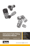
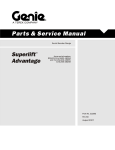
Calibration and Switching Module AA Swagelok Swagelok®® Pre-Engineered Pre-Engineered Subsystem Subsystem • Pre-engineered subsystems available in weeks, not months. • Field-tested design ensures optimum system performance. User’s Manual Contents Calibration and Switching Module System Manual . . . . . . . 3 Introduction . . . . . . . . . . . . . . . . . . . . . . . . . . . . 4 Inlet Assembly Configurations . . . . . . . . . . . . . . . . . . 6 Mounting . . . . . . . . . . . . . . . . . . . . . . . . . . . . . 10 Installation . . . . . . . . . . . . . . . . . . . . . . . . . . . . 12 Manual Calibration Option . . . . . . . . . . . . . . . . . . . . 17 System Startup . . . . . . . . . . . . . . . . . . . . . . . . . . 18 Operation . . . . . . . . . . . . . . . . . . . . . . . . . . . . . 19 Maintenance . . . . . . . . . . . . . . . . . . . . . . . . . . . 20 Troubleshooting . . . . . . . . . . . . . . . . . . . . . . . . . . 22 System Component User Instructions . . . . . . . . . . . . . . 25 Swagelok Instructions Swagelok Tube Fitting Instructions for 1 in. (25 mm) and smaller fittings, MS-12-01 . . . . . . . . . . . . . . . . . . 25 Packing Adjustment for 40 Series Ball Valves, MS-INS-40 . . . . . . . . . . . . . . . . . . . . . . . . . . . . . 26 Stream Selector Valve (SSV) Series Assembly and Service Instructions, MS-CRD-SSV . . . . . . . . . . . . . . . 27 TF and F Series Filter Service Instructions, MS-CRD-0007 . . . . . . . . . . . . . . . . . . . . . . . . . . 33 KCP Series Regulator Maintenance Instructions, MS-CRD-0109 . . . . . . . . . . . . . . . . . . . 36 Pressure Regulators User Guide, MS-CRD-KREG . . . . . . . . . . . . . . . . . . . . . . . . . . 41 Variable Area Flowmeters Installation Instructions, MS-CRD-0111 . . . . . . . . . . . . . . . . . . . . . . . . . . . 43 A Swagelok Pre-Engineered Subsystem Calibration and Switching Module 3 Calibration and Switching Module (CSM) System Manual Gas System with Three Sample Inlet Assemblies and Two Calibration Inlet Assemblies Shown with Bypass, ARV, and Manual Calibration Options A Swagelok Pre-Engineered Subsystem Calibration and Switching Module 4 Introduction The Calibration and Switching Module (CSM) is a part of an analytical sampling system. The CSM selects the process or calibration fluid, which is then directed to a process analyzer. The CSM contains multiple streams with modular components, including a stream selector system (SSV series). The series of components which handle the process fluid are called sample inlet assemblies. The series of components which handle calibration fluids are called calibration inlet assemblies. The SSV within each stream selects a fluid for analysis in response to a pneumatic‑pressure signal from an external source, typically the analyzer. The signal opens one of the SSV’s double‑block-and-bleed valve modules corresponding to the stream containing the fluid to be analyzed. The selected fluid flows through the CSM to the process analyzer. A Swagelok Pre-Engineered Subsystem Calibration and Switching Module 5 Introduction Gas System with Three Sample Inlet Assemblies and Two Calibration Inlet Assemblies Shown with Bypass, ARV, and Manual Calibration Options SHV PSV C PI PI PI BV PI PI BV FP PR RV PI MV FI SSV A Swagelok Pre-Engineered Subsystem CV Calibration and Switching Module 6 PR FP PR PR FP FP Inlet Assembly Configurations FM FM FM PR FP FP MV MV FI NV PR FI MV FP FP FM RV NV RV FPMV BV CV SSV SHV RV SSV PI CV MV PSV PV FP RV PSV BV SHV NV1 SHV PSV SSV SHV PV SHV NV NV FC PV PV NV NV SN Stream selector valve FFL PV FI MV NV C NV1 PSV BV FI PI NV SHV NV CV Stream selector valve SHV SN SSV NV BV PSV SN CV regulator SN NV NV SN C FI Valve Inlet Assembly (VIA) BV PV SN Relief SSVvalve BV SSV RV C FP FM NV1 SHV CV FI SSV Pneumatic switching FM valve BV FI PV PI SHV Shuttle SN valve RV CV C NV BV RV NV SN C PV FI BVBV Pressure SN SSV BV NV1 FFL NV RV SHV CV CV SSV PR PI RV FI FI PI Pressure indicator SHV Metering valveNV1 SN MV BV FI PSV FI FI Filter - particulate SSV NV FI CV MV FFL FM FM PI NV RV BV C FC PSV SN PI FFL FP CV FC FM FI C NV1 PSV NV1 PSV SHV PSV FC C MV C FFL C Needle valve NV FI FM Flow indicator FI FP PI NV1 NV FM PR NV1 FI FI FC CV FI Check valve CV PI NV FM MV PSV FI FI NV1 BV FP Ball MVvalve NV1 BV PI FFL C FFL FM C PSV FP BV PI FFL NV1 PR BV FC FM Configuration FISymbols BV FFL PI MV FC FM FI FC FP FM BV FM FC FP FP PR FP FM BV FM PR FC FP FM FP FP FM FFL YourFC CSM will be configured using one of these six inlet assemblies plus any selected outlet FC FP FFL PR configuration and options. See theFMCalibration and Switching Module Application Guide, FFL FP FM MS‑02-360, for additional information. FM PR FP PV RV SN NV RV BV SSV PV SSV PV NV NV Ball valve BV BV BV SSV Sample Inlet BV Common Vent A Swagelok Pre-Engineered Subsystem Outlet Flow Loop Calibration and Switching Module PV NV 7 Inlet Assembly Configurations Stream selector valve Gauge Inlet Assembly (GIA) Pressure indicator Ball valve SSV PI Sample Inlet BV Common Vent Filter Inlet Assembly (FIA) Outlet Flow Loop Stream selector valve Only assembly for calibration inlets Pressure indicator Filter Ball valve SSV PI Sample Inlet BV FP Common Vent A Swagelok Pre-Engineered Subsystem Outlet Flow Loop Calibration and Switching Module 8 Inlet Assembly Configurations Stream selector valve Relief Inlet Assembly (RIA) Pressure indicator Relief valve Filter Ball valve SSV PI Sample Inlet BV FP RV Common Vent Pressure Regulator Inlet Assembly (PIA) Relief valve Pressure indicator Outlet Flow Loop Stream selector valve Pressure regulator Filter Ball valve SSV PI Sample Inlet BV FP PR RV Common Vent A Swagelok Pre-Engineered Subsystem Calibration and Switching Module Outlet Flow Loop 9 Inlet Assembly Configurations Flow Loop Inlet Assembly (LIA) Stream selector valve Pressure indicator Relief valve Flow indicator Filter Ball valve 2 Sample (inlet) inlet Ball valve 1 (loop) PI1 Bypass Outlet FI RV Sample Inlet BV1 NV NV (Liquid) (Gas) BV2 FP SSV Common Vent A Swagelok Pre-Engineered Subsystem Outlet Flow Loop Calibration and Switching Module 10 Mounting The size of the mounting plate is dependent on the number and type of sample streams, the number of calibration streams, options included, and fluid type (gas or liquid). The tables on the next page contain the mounting plate dimensions. Attach with fasteners with a maximum diameter of 1/4 in. or 6 mm (not provided) in the four mounting holes on the plate. Note: C SM systems containing flow indicator(s) must be installed vertically, allowing the flow through the flow indicator(s) to be in the upward direction. Dimensions, in inches (millimeters) are for reference only and are subject to change. CSM Configuration A CSM with flow indicator or relief valve CSM with flow loop inlet assembly 5.50 (14.0) 4 mounting holes for 1/4 in./6 mm socket head cap screw or hex head bolt, or similar fastener 1.09 (27.7) 1.00 (25.4) W 0.75 (19.0) L A Swagelok Pre-Engineered Subsystem Calibration and Switching Module A in. (mm) 6.80 (173) 8.75 (222) 11 Mounting Dimensions, in inches (millimeters) are for reference only and are subject to change. Plate Dimension L Dimension L, in. (mm) Bypass Option No Inlet Stream Configuration Designator No Yes Yes / No Yes / No Manual Calibration No No No Yes Yes 3, A, X 1, 2 Outlet Designator 3, X FFilter (FIA) GGauge (GIA) LFlow loop (LIA), 1 inlet LFlow loop (LIA), 2 inlets LFlow loop (LIA), 3 or more inlets PPressure regulator (PIA) RRelief valve (RIA) V Valve (VIA) 1, 2, A All 12.0 (305) 15.0 (381) 15.0 (381) 18.0 (457) 23.0 (584) 12.0 (305) 15.0 (381) 15.0 (381) 18.0 (457) 23.0 (584) 23.0 (584) 28.0 (711) 28.0 (711) 28.0 (711) 28.0 (711) 23.0 (584) 28.0 (711) 28.0 (711) 28.0 (711) 34.0 (864) 28.0 (711) 28.0 (711) 28.0 (711) 34.0 (864) 34.0 (864) 15.0 (381) 23.0 (584) 23.0 (584) 23.0 (584) 23.0 (584) 15.0 (381) 18.0 (457) 18.0 (457) 18.0 (457) 23.0 (584) 12.0 (305) 15.0 (381) 15.0 (381) 18.0 (457) 23.0 (584) Plate Dimension W Dimension W, in. (mm) Bypass Option Number of Inlet Streams No No Yes Yes / No Yes / No No Yes Yes No Yes Yes / No Yes / No Manual Calibration No Yes Outlet Designator 2 3 4 5 6 7 8 9 10 11 12 2, X 1 X 1, 2 1,2,X 3, A 3, A 12.0 (305) 12.0 (305) 15.0 (381) 18.0 (457) 18.0 (457) 18.0 (457) 23.0 (584) 23.0 (584) 23.0 (584) 28.0 (711) 28.0 (711) 15.0 (381) 15.0 (381) 15.0 (381) 18.0 (457) 18.0 (457) 18.0 (457) 23.0 (584) 23.0 (584) 23.0 (584) 28.0 (711) 28.0 (711) 12.0 (305) 15.0 (381) 15.0 (381) 18.0 (457) 18.0 (457) 23.0 (584) 23.0 (584) 23.0 (584) 28.0 (711) 28.0 (711) 28.0 (711) 18.0 (457) 18.0 (457) 18.0 (457) 18.0 (457) 23.0 (584) 23.0 (584) 23.0 (584) 28.0 (711) 28.0 (711) 28.0 (711) 34.0 (864) 18.0 (457) 18.0 (457) 18.0 (457) 23.0 (584) 23.0 (584) 23.0 (584) 23.0 (584) 28.0 (711) 28.0 (711) 28.0 (711) 34.0 (864) 15.0 (381) 18.0 (457) 18.0 (457) 23.0 (584) 23.0 (584) 23.0 (584) 23.0 (584) 28.0 (711) 28.0 (711) 28.0 (711) 34.0 (864) 18.0 (457) 23.0 (584) 23.0 (584) 23.0 (584) 28.0 (711) 28.0 (711) 28.0 (711) 34.0 (864) 34.0 (864) 34.0 (864) 34.0 (864) A Swagelok Pre-Engineered Subsystem Calibration and Switching Module 12 Installation The assemblies within the CSM are color coded: Blue Process sample assemblies Orange Calibration assemblies Green Bypass assemblies White Outlet assemblies Note: C lose all inlet ball valves before connecting the CSM to your system. Assemble all connections according to the Swagelok Tube Fitting Instructions for 1 in. (25 mm) and smaller fittings, page 25. Bypass option pneumatic supply connection Manual calibration outlet Bypass outlet Manual calibration pneumatic supply connection Pneumatic supply connection with bypass option and no manual calibration option Calibration inlets Calibration inlet pneumatic supply connection with bypass option Process inlets Pneumatic supply connections Relief valve vent ARV outlet to analyzer SSV vent ARV inlet from analyzer Gas System shown with Bypass, ARV, and Manual Calibration Options A Swagelok Pre-Engineered Subsystem Calibration and Switching Module ARV outlet to low-pressure header 13 Installation Connecting Inlets of the CSM Process inlets (all assemblies except for flow loop inlet assembly) Connect the tubing from the process sample line to the tube fitting adjacent to the blue lockdown bar on the inlet assembly. The bar identifies each sample stream. The fitting size is either 1/4 in. or 6 mm. Return Connection, flow loop Connect the tubing leading to the process return to the flow loop assembly at the tube fitting adjacent to the blue lockdown bar on the flow loop assembly. The bar identifies each sample stream. The fitting size is either 1/4 in. or 6 mm. Process inlet, flow loop Connect the tubing from the process line to the tube fitting with the blue tag on the inlet assembly. The bar identifies each sample stream. The fitting size is either 1/4 in. or 6 mm. A Swagelok Pre-Engineered Subsystem Calibration and Switching Module 14 Installation Calibration inlets Connect tubing from the calibration source to the tube fitting adjacent to the orange lockdown bar. The bar identifies each calibration stream. The fitting size is 1/8 in. or 3 mm. SSV actuator pneumatic inlets 1. C onnect the pneumatic supply line to the fittings on the side of the SSV actuator. The fitting size is 1/8 in. or 3 mm. The working pressure range is 40 to 150 psig (2.8 to 10.3 bar) for CSM systems without the bypass option and 40 to 100 psig (2.8 to 6.8 bar) for systems with the bypass option. Note: If your CSM includes the manual calibration option, there will be no direct connection to the calibration inlet SSV pneumatic actuators. Fitting for pnueumatic supply line Fitting for pnueumatic supply line A Swagelok Pre-Engineered Subsystem Calibration and Switching Module 15 Installation Connecting Outlets of the CSM Your CSM will have one of the following outlet configurations. ARV outlet configuration System connections - the fitting size is either 1/8 in. or 3 mm. 2. Connect the tubing leading to the process analyzer to the tube fitting adjacent to the white lockdown bar marked “AO”. 3. Connect the tubing coming from the process analyzer to the tube fitting adjacent to the white lockdown bar labeled “AI”. 4. Connect the tubing leading to the reference vent to the tube fitting adjacent to the white lockdown bar labeled “AV”. ARV pneumatic inlets Outlet configuration 1, upstream flowmeter Connect the tubing leading to the process analyzer to the tube fitting adjacent to the white lockdown bar labeled “AO”. The fitting size is either 1/8 in. or 3 mm. Outlet configuration 2, upstream metering valve Connect the tubing leading to the process analyzer to the tube fitting adjacent to the white lockdown bar marked “AO”. The fitting size is either 1/8 in. or 3 mm. ARV outlet, SSV actuator pneumatic inlet Connect the tubing to the two tube fittings adjacent to the white lockdown bar. Connect the tubing to the pneumatic supply line. The fitting size is either 1/8 in. or 3 mm. Note: U se the same supply line as the process inlets for the ARV SSV actuators to ensure simultaneous actuation. A Swagelok Pre-Engineered Subsystem Calibration and Switching Module 16 Installation Outlet configuration 3, downstream flowmeter Connecting Remaining CSM Connections 1. Connect the tubing leading to the process analyzer to the tube fitting adjacent to the white lockdown bar labeled “AO”. The fitting size is either 1/8 in. or 3 mm. System vent connections 1. Connect the system vent on the SSV end block to a sample disposal. The fitting size is either 1/8 in. or 3 mm. Note: See Stream Selector System For Process Analyzer Applications, MS-02-326, for information on an alternate vent location. 2. Connect the vents from the relief valves in pressure regulator inlet assemblies, relief inlet assemblies, and flow loop inlet assemblies to a sample disposal. The fitting size is either 1/4 in. or 6 mm. 2. Connect the tubing leading from the process analyzer to the tube fitting adjacent to the white lockdown bar labeled “AI”. 3. Connect the tubing leading back to the process or disposal to the tube fitting adjacent to the white lockdown bar labeled “REC”. Bypass option (when present) 1. Connect the tubing leading to the system bypass outlet to the tube fitting adjacent to the green lockdown bar labeled “BO”. The fitting size is either 1/4 in. or 6 mm. 2. CSMs without manual calibration option: connect the pneumatic supply line to the fitting adjacent to the green lockdown bar labeled “PNI”. The fitting size is 1/8 in. or 3 mm. Outlet configuration X, no flow control Connect the tubing leading to the process analyzer to the tube fitting adjacent to the white lockdown bar labeled “AO”. The fitting size is either 1/8 in. or 3 mm. A Swagelok Pre-Engineered Subsystem Calibration and Switching Module 17 Manual Calibration Option Installation The manual calibration option is available with one or two calibration inlets. It can be operated in three different modes, depending on your system and the desired function. All fittings are either 1/8 in. or 3 mm. Assemble all connections according to the Swagelok Tube Fitting Instructions for 1 in. (25 mm) and smaller fittings, page 25. One Calibration Inlet 1. Connect a pneumatic supply line to A. 2. Remove the installed plug and connect the pneumatic signal line(s) from the analyzer to B. 3. Remove the installed plug and connect the pneumatic supply line going to the analyzer to D. Mode 3 — Manual Calibration only Mode 1 — Automatic and Manual Calibration with an Independent Pneumatic Supply Two Calibration Inlets 1. Connect a pneumatic supply line to A. 2. Verify there are plugs in B, C, and D. Two Calibration Inlets 1. Connect a pneumatic supply line to A. 2. Remove the installed plugs and connect the pneumatic signal line(s) from the analyzer to B and ‘C. 3. Verify there is a plug in D. One Calibration Inlet 1. Connect a pneumatic supply line to A. 2. Verify there are plugs in B and D. One Calibration Inlet 1. Connect a pneumatic supply line to A. 2. Remove the installed plug and connect the pneumatic signal line(s) from the analyzer to B. 3. Verify there is a plug in D. Notice The analyzer will remain in control of the sample inlets and the calibration inlet not set to MANUAL. There is the possibility of a mixture of calibration and/or sample fluids if the analyzer sends a signal to the CSM. A Notice The analyzer is in control of the sample inlets and the calibration inlet when not set to MANUAL. There is the possibility of a mixture of calibration and/or sample fluids if the analyzer sends a signal to the CSM. D Mode 2 — Automatic and Manual Calibration with the Pneumatic Supply to Analyzer Routed through Manual Calibration Assembly B One Calibration Inlet A Note - T he purpose of this mode is to prevent inadvertent pneumatic signals from the analyzer to the CSM inlets. The ARV option must still be connected to a pneumatic supply line to allow those SSV’s to open. Two Calibration Inlets 1. Connect a pneumatic supply line to A. 2. Remove the installed plugs and connect the pneumatic signal line(s) from the analyzer to ‘B and ‘C. 3. Remove the installed plug and connect the pneumatic supply line going to the analyzer to D. B D A Swagelok Pre-Engineered Subsystem C Two Calibration Inlets Calibration and Switching Module 18 System Startup 1. CSM with flow loop inlet assemblies or the bypass option - open the metering valve(s) on the flowmeter(s) by turning the handle counterclockwise until it stops. 2. Shut off the flow to the analyzer by turning the metering valve handle clockwise until it stops. (For outlet configurations 1 and 3 the metering valve is on the flowmeter.) Note: O utlet configuration X does not contain a flow control device to the analyzer. 3. Open all of the sample inlet ball valves. Note: F low loop sample inlets will display flow on the flowmeter(s). Flow can be adjusted by turning the handle of the metering valve on the flowmeter clockwise to decrease flow or counter clockwise to increase flow. 4. For systems with pressure regulator inlet assemblies, adjust all of the sample inlet regulators to the same pressure to maintain similar flow rates to the analyzer. 5. Send a pneumatic signal to the first sample inlet SSV actuator to confirm valve actuation. For systems with the bypass option, you should see full flow to the bypass flowmeter. Open the analyzer metering valve until the desired flow rate is indicated on the analyzer flowmeter. Bypass flow can be adjusted by partially closing the bypass metering valve. 6. Close the inlet SSV actuators by removing the pneumatic signal. 7. Repeat steps 5 and 6 for the other sample inlets. 8. Open all of the calibration inlet ball valves. 9. Send a pneumatic signal to the first calibration inlet SSV actuator to confirm valve actuation. For systems with the bypass option, the bypass SSV should be closed and you should see no flow to the bypass valve. 10.Close the calibration SSV actuators by removing the pneumatic signal. 11.Repeat steps 9 and 10 for the other calibration inlet. Bypass option flowmeter valve Metering valve Gas System shown with Bypass Option, Outlet Option 2 A Swagelok Pre-Engineered Subsystem Calibration and Switching Module 19 Operation 1. Verify all sample and calibration inlet ball valves are open. 2. The sample and calibration inlet SSV valves will be opened by your control system (not included). 3. Adjust the flow loop assembly or the bypass flow rate by opening or closing the metering valve on the flowmeter(s) on those lines as needed. 4. Adjust flow to the analyzer by turning the metering valve handle counterclockwise to increase flow or clockwise to decrease flow. (For outlet configurations 1 and 3 the metering valve is on the flowmeter.) Note: O utlet configuration X does not contain a flow control device to the analyzer. 5. To isolate an inlet, close that inlet’s ball valve. 6. For a pressure regulator inlet, turn the regulator handle clockwise to increase the pressure or counter clockwise to decrease the pressure. Manual Calibration Option For Modes 1 and 2, the calibration inlet stream actuator(s) are connected to the pneumatic signal lines coming from the analyzer when the calibration valve(s) are in the AUTO/OFF position. This allows calibration to be controlled by the analyzer. For Mode 3, manual calibration only, the AUTO/OFF position for this mode is off, as there are no calibration pneumatic signal connections made to the analyzer. ■For normal operation, place the CAL 1 valve and the CAL 2 valve in the AUTO/ OFF position. ■To select calibration stream 1 for analysis by the process analyzer, rotate the CAL 1 valve to the manual position, leaving the CAL 2 valve in the AUTO/ OFF position. ■To select calibration stream 2 for analysis by the process analyzer, rotate the CAL 2 valve to the MANUAL position, leaving the CAL 1 valve in the AUTO/OFF position. Note: T he system is not intended to have both manual calibration valves simultaneously placed in the MANUAL position Note: A ny manual or automatic calibration activity will shut off the bypass stream, preventing loss of calibration fluids through the bypass stream. A Swagelok Pre-Engineered Subsystem Calibration and Switching Module 20 Maintenance Warning Before servicing any installed system component you must ■ purge the system ■ depressurize the system. Follow these steps to depressurize your CSM: 1. Close the isolation valves upstream of the process inlet. 2. Close the calibration source flow upstream of the calibration inlets. 3. Open the ball valves on all sample inlet and calibration inlets. 4. Systems with a Pressure Regulator Inlet Assembly — Adjust the pressure regulators to an acceptable pressure. Do not leave the regulators in the closed position. 5. Open the metering valves on the sample assembly outlet and the bypass outlet flow meter. 6. Open the sample inlet and calibration inlet SSV valves by applying a pneumatic signal to each SSV actuator. 7. Depressurize the CSM by opening a vent regulator or vent valve downstream of the CSM. 8. Prior to disassembly, confirm that there is no pressure in the line(s) downstream of the bypass or ARV check valve(s). Periodically check the operation of system relief valves using one of the following methods: 5. Remove the outlet adapter from the top of the valve, tighten or loosen the adjusting screw as necessary, then replace the outlet adapter. Reverse steps 1 through 3 of Relief Valve Removed From System and reinstall the relief valve. Alternatively, replace the relief valve. Relief Valve Removed from System 1. When multiple inlets are present, remove the relief valve outlet header. 2. Unscrew the screws attaching the relief valves to the substrate and remove the valves from the substrate. 3. Remove the modular adapters and exhaust manifold from the valves. 4. Connect each valve to an external pressure supply (1/4 in. NPT connection) and a suitable exhaust header (1/4 in. Swagelok tube fitting connection). 5. Slowly increase the pressure until the valve opens. 6. Decrease the pressure until the valve closes. 7. If proper operation has been observed, reverse steps 1 through 3 and reinstall the relief valve. If the valve does not open at the set pressure (factory set to 75 % of the pressure gauge range), remove the outlet adapter from the top of the valve, tighten or loosen the adjusting screw as necessary, then replace the outlet adapter. Reverse steps 1 through 3 and reinstall the relief valve. Alternatively, replace the relief valve. Relief Valve in System 1. Connect a variable pressure source to the sample assembly inlet. 2. Slowly increase the pressure until the valve opens. 3. Decrease the pressure until the valve closes. 4. If the valve does not open at the set pressure (factory set to 75 % of the pressure gauge range), remove the valve from the system according to steps 1 through 3 of Relief Valve Removed From System. A Swagelok Pre-Engineered Subsystem Calibration and Switching Module 21 Maintenance System Component Reference for Replacement Ordering Information Ball Valve (42T series) Modular Platform Components (MPC), MS‑02‑185 Check Valve (CH series) Modular Platform Components (MPC), MS‑02‑185 Filter (TF series) Modular Platform Components (MPC), MS‑02‑185 Filter element Filters, MS-01-92 Metering Valve (M series) Modular Platform Components (MPC), MS‑02‑185 Pressure regulator (KCP series) Modular Platform Components (MPC), MS‑02‑185 Relief valve (KVV series) Pressure Regulators, MS‑02‑230 Pressure indicator (M model pressure gauge) Modular Platform Components (MPC), MS‑02‑185 Stream selector valve (SSV series) Modular Platform Components (MPC), MS‑02‑185 Stream Selector System for Process Analyzer Applications, MS-02-326 Flow indicator (G1 and M1 series variable area flowmeter) Variable Area Flowmeters, MS-02-346 A Swagelok Pre-Engineered Subsystem Calibration and Switching Module 22 Troubleshooting Symptom Cause Remedy The filter in the open stream is obstructed. Clean or replace the filter element or the filter. The metering valve is adjusted incorrectly. Adjust the metering valve setting by turning the handle counterclockwise to increase the flow. Flowmeter to the analyzer is indicating The inlet regulator is adjusted too low flow. low. (If process stream of your CSM is not a pressure regulator inlet assembly, this is the regulator upstream of the CSM.) Adjust the regulator setting by turning the handle clockwise to increase the pressure. The system supply flow rate to the CSM has decreased. Check and adjust the flow upstream of the CSM as necessary. The metering valve is adjusted incorrectly. Adjust the metering valve setting by turning the handle clockwise to decrease the flow. Flowmeter to the The inlet regulator is adjusted too analyzer is indicating high. high flow. Adjust the regulator setting by turning the handle counterclockwise to lower the pressure. The system supply flow rate to the CSM has increased. Check and adjust the flow upstream of the CSM as necessary. The metering valve is adjusted incorrectly. Adjust the metering valve setting by turning the handle counterclockwise to increase the flow. The filter in the open stream is obstructed. Clean or replace the filter element or the filter. Bypass flowmeter is indicating low flow. Bypass flowmeter is The metering valve is adjusted indicating high flow. incorrectly. The metering valve is adjusted incorrectly. Flow loop inlet assembly flowmeter The inlet regulator is adjusted too is indicating low low. flow. The system supply flow rate to the CSM has decreased. A Swagelok Pre-Engineered Subsystem Adjust the metering valve setting by turning the handle clockwise to decrease the flow. Adjust the metering valve setting by turning the handle counterclockwise to increase the flow. Adjust the regulator setting by turning the handle clockwise to increase the pressure. Check and adjust the flow upstream of the CSM as necessary. Calibration and Switching Module 23 Troubleshooting Symptom Cause Remedy The metering valve is adjusted incorrectly. Adjust the metering valve setting by turning the handle clockwise to decrease the flow. Flow loop inlet assembly flowmeter The inlet regulator is adjusted too is indicating high high. flow. A sample inlet pressure gauge is indicating low pressure. A sample inlet pressure gauge is indicating high pressure. A calibration inlet pressure gauge is indicating low pressure. A calibration inlet pressure gauge is indicating high pressure. Adjust the regulator setting by turning the handle counterclockwise to lower the pressure. The system supply flow rate to the CSM has increased. Check and adjust the flow as necessary. The filter in the open stream is obstructed. Clean or replace the filter element or the filter. The inlet regulator is adjusted too low. Adjust the regulator setting by turning the handle clockwise to increase the pressure. The system supply flow rate to the CSM has decreased. Check and adjust the flow upstream of the CSM as necessary. The inlet regulator is adjusted too high. Adjust the regulator setting by turning the handle counterclockwise to lower the pressure. The system supply flow rate to the CSM has increased. Check and adjust the flow upstream of the CSM as necessary. The filter in the open stream is obstructed. Clean or replace the filter element or the filter. The calibration supply gas is running low. Replace the calibration supply gas. The calibration supply pressure is set too high. Lower the calibration supply pressure. The analyzer returns readings Process fluid mixes with calibration significantly different fluid during manual calibration. than expected. Adjust the operating procedure for calibration to ensure no inlet stream will be selected during manual calibration. Verify the appropriate manual calibration mode has been selected for your system. A Swagelok Pre-Engineered Subsystem Calibration and Switching Module 24 Troubleshooting Symptom Cause Remedy The pneumatic supply line pressure Increase the pneumatic supply line pressure. is below 40 psig (2.8 bar). A SSV valve piston does not fully actuate. The SSV valve is not functioning properly. Replace the valve seals according to SSV Series Assembly and Service Instructions, page 27. Manual calibration option - the valve is set to manual. Turn valve handle to AUTO/OFF. The pneumatic control system is not functioning properly. Check the pneumatic control system. A Swagelok Pre-Engineered Subsystem Calibration and Switching Module 25 Swagelok Tube Fitting Instructions for 1 in. (25 mm) and smaller fittings Installation These instructions apply to both traditional fittings and to fittings with the advanced backferrule geometry. 1.Fully insert the tube into the fitting and against the shoulder; rotate the nut fingertight. Fig. 1. High-Pressure Applications and High Safety-Factor Systems: Further tighten the nut until the tube will not turn by hand or move axially in the fitting. 2.Mark the nut at the 6 o’clock position. Fig. 2. 3.While holding the fitting body steady, tighten the nut one and one-quarter turns to the 9 o’clock position. Fig. 3. Note: For 1/16, 1/8, and 3/16 in.; 2, 3, and 4 mm tube fittings, tighten the nut three‑quarters turn to the 3 o’clock position. Gaugeability On initial installation, the Swagelok gap inspection gauge assures the installer or inspector that a fitting has been sufficiently tightened. Fig. 1 Fig. 2 Fig. 3 Position the Swagelok gap inspection gauge next to the gap between the nut and body. Fig. 4. • If the gauge will not enter the gap, the fitting is sufficiently tightened. • If the gauge will enter the gap, additional tightening is required. Reassembly Instructions — You may disassemble and reassemble Swagelok tube fittings many times. Fig. 4 Warning Always depressurize the system before disassembling a Swagelok tube fitting. 1.Prior to disassembly, mark the tube at the back of the nut; mark a line along the nut and fitting body flats. Fig. 5. Use these marks to ensure you return the nut to the previously pulled-up position. 2.Insert the tube with preswaged ferrules into the fitting body until the front ferrule seats against the fitting body. Fig. 6. 3.While holding the fitting body steady, rotate the nut with a wrench to the previously pulled-up position as indicated by the marks on the tube and the flats; at this point you will feel a significant increase in resistance. Fig. 7. 4.Tighten the nut slightly. Fig. 5 Fig. 6 Caution Do not use the gap inspection gauge with reassembled fittings. Fig. 7 Caution Do not mix or interchange parts with those of other manufacturers. For additional information, see the Gaugeable Tube Fittings and Adapter Fittings catalog, MS-01-140. A Swagelok Pre-Engineered Subsystem Calibration and Switching Module 26 40 Series Valve Packing Adjustment IMPORTANT This valve is adjusted for factory testing with nitrogen at 1000 psig (69 bar) or the rated pressure if lower than 1000 psig (69 bar). Packing must be readjusted for service at higher than test pressure. Warning: Packing adjustment may be required during the service life of the valve to prevent leakage. Before servicing any installed valve you must depressurize the system, cycle the valve, and purge the valve. Adjust the packing by turning the packing bolt clockwise in 1/16‑turn increments until leak-tight performance is achieved. Always verify proper operation upon installation. A Swagelok Pre-Engineered Subsystem Calibration and Switching Module 27 SSV Series Assembly and Service Instructions Contents • Tool Requirements . . . . . . . . . . . . 1 • Components and Hardware . . . . . 2 Base Blocks . . . . . . . . . . . . . . . . . 5 • Port and Mounting Dimensions . . 3 • Flange Replacement . . . . . . . . . . . 5 • General SSV Assembly . . . . . . . . . 4 • Cap Replacement . . . . . . . . . . . . . 6 • Mounting MPC-Style •O-Ring Replacement . . . . . . . . . . 6 Assemblies . . . . . . . . . . . . . . . . . . • Adding / Removing 5 Tool Requirements Torque Wrench, 0 to 45 in.∙lb (0 to 5.1 N∙m) with hex drivers: • 7/64 in. • 9/64 in. • 5/32 in. O-Ring Pick (or similar tool) A Swagelok Pre-Engineered Subsystem Calibration and Switching Module 28 SSV Series Assembly and Service Instructions Components and Hardware Base Block ∙ ∙ ∙ ∙ Flange Standard Outlet MPC Standard MPC Outlet ARV Base Block Cap ∙T en per bag of chosen color End Base Block Screws ∙ Right ∙ Left ∙ ∙ ∙ ∙ Module O-Rings ∙ DBB ∙ ARV ∙ Three 9-004 ∙ Eight 9-007 ∙ One 9-022 A Swagelok Pre-Engineered Subsystem Standard MPC mounting Flange Insert Calibration and Switching Module 29 SSV Series Assembly and Service Instructions Port and Mounting Dimensions Dimensions, in inches (millimeters), are for reference only and are subject to change. Air gap vent 2.76 (70.1) Inlet port 0.75 (19.0) 0.80 (20.3) Inlet View 1.50 (38.1) 1.125 (28.6) 0.68 (17.3) to vent port (not shown) 6.37 (162) (add 1.6 in. (40.6 mm) for additional streams) Top View 4.13 (105) Air inlet port 1.70 (43.2) 1.05 (26.7) 0.53 Outlet port to vent port (not shown) 0.50 (12.7) 1.02 (13.5) 1.60 (40.6) 1.30 (33.0) (25.9) 0.98 (24.9) Outlet View A Swagelok Pre-Engineered Subsystem Calibration and Switching Module 30 SSV Series Assembly and Service Instructions Through ports General SSV Assembly 1.Place a left end base block in a vise. Note: F or assemblies using an ARV base block, the ARV block is in place of a left end base block. 2.Place a base block on the left end base block, aligning the O-rings (9-007) with the through ports. The square end of the left end base block inserts will be located in the counterbores of the base block. See Fig. 1. O-rings Inserts Counterbores Base block Left end base block Fig. 1 Base block insert 3.Tighten the two base block insert screws to the two left end base block inserts using a 9/64 in. hex torque wrench placed through the base block inserts to 35 to 45 in.∙lb (4.0 to 5.1 N∙m). See Fig. 2. 4.Continue building the base block assembly by repeating steps 2 and 3, tightening the base block insert screws to the adjacent base block inserts. Place the outlet base block in the desired position within the base block assembly. Caution Do not intermix standard and MPC‑style base blocks. Note: It is recommended that the outlet base block be assembled close to the center of the assembly for the most consistent flow results. 5.Assemble a right end base block to the assembly, aligning the right end base block O-rings (9-007) with the through ports on the last base block. Tighten the right end base block insert screws to the base block inserts to 35 to 45 in.∙lb (4.0 to 5.1 N∙m) using a 9/64 in. hex torque wrench placed through the end base block. See Fig. 3. Fig. 2 Through ports O-rings Base block assembly Fig. 3 DBB module Mounting screw 6.Install a DBB module on each base block with the alignment pin fitting into the alignment hole on the DBB module. Using two mounting screws (#10-32 x 1/2 in. with standard 5/32 in. hex drive) tighten the DBB module to the base block to 25 to 35 in.∙lb (2.8 to 4.0 N∙m). See Fig. 4. Base block Note: F or ARV assemblies, install only ARV modules to the ARV base blocks. A Swagelok Pre-Engineered Subsystem Right end base block Calibration and Switching Module Mounting screw Alignment hole Alignment pin Fig. 4 31 SSV Series Assembly and Service Instructions SSV assembly Mounting MPC-Style Assemblies For MPC-style assemblies, install the entire SSV assembly to the panel using MPC mounting screws (#10-32 x 2.0 in. with standard 5/32 in. hex head), aligning the fluid port holes on the SSV assembly and the panel. Torque the screws to 25 to 35 in.∙lb (2.8 to 4.0 N∙m). See Fig. 5. Mounting screw Fluid port hole O-rings Panel Fig. 5 Adding / Removing Base Blocks 1.Remove the insert screws from the right end base block. Add (according to step 4 of General SSV Assembly) or remove the desired number of base blocks using a 9/64 in. hex tool. 2.Replace the right end block according to step 5 of General SSV Assembly. W ARNING Before servicing any installed valve you must: • depressurize the system • cycle the valve • purge the valve. 3.Install any needed DBB modules per step 6 of General SSV Assembly. Flange Replacement 1.Using a 5/32 in. hex torque wrench, loosen the mounting screws and remove the DBB module from the base block. 2.Using a 7/64 in. hex torque wrench, loosen the flange screws and remove the flange from the DBB module. DBB module 3.Align the air inlet and alignment pin holes on the new flange with those on the bottom of the DBB module. See Fig. 6. CAUTION The air inlet and alignment pin holes on the flange and valve must be oriented correctly for the DBB module to function correctly after reassembly. Alignment pin hole Air actuation hole Flange screws (4) Flange 4.Replace the flange screws and tighten (10 to 15 in.·lb, 1.1 to 1.7 N·m). 5.Attach the DBB module to the base block per step 6 of General SSV Assembly. A Swagelok Pre-Engineered Subsystem Fig. 6 Calibration and Switching Module 32 SSV Series Assembly and Service Instructions Cap Piston Groove Cap Replacement Tabs Undercut 1.Use an O-ring pick or similar tool to remove the existing cap. 2.Press the new cap into the groove so that the tabs are compressed within the undercut of the piston. See Fig. 7. O-Ring Replacement 1.To replace base block seals or right end base block seals (9-007), remove block(s) according to Adding/ Removing Base Blocks. See Fig. 8. Fig. 7 DBB module face seals Base block seals 2.To replace the DBB module face seals (9‑007), remove the module from the base block according to step 1 of Flange Replacement. See Fig. 8. 3.To replace the DBB module body seal (9‑022) or actuation air seal (9-004), remove the module and flange according to steps 1 and 2 of Flange Replacement. See Fig. 9. 4.Remove the O-ring from the counterbore using an O-ring pick or similar tool. C AUTION Be careful not to scratch the counterbore surface with the removal tool. System performance could be affected by any scratches. 5.For the DBB module body seal (9-022) only, lubricate the new O-ring with the provided lubricant. Right end base block seals Fig. 8 DBB module body seal 6.Press the new O-ring(s) into the appropriate counterbore. Air actuation seal 7.Reassemble the SSV assembly according to the section followed for disassembly. Testing Fig. 9 Perform a shell test and check for proper operation prior to system installation. Safe Product Selection When selecting a product the total system design must be considered to ensure safe, trouble-free performance. Function, material compatibility, adequate ratings, proper installation, operation, and maintenance are the responsibilities of the system designer and user. A Swagelok Pre-Engineered Subsystem Caution: Do not mix or interchange parts with those of other manufacturers. Calibration and Switching Module 33 TF Series Tee-Type Filter Service Instructions Tools Required Kit Contents Gasket Kit Element Kit Tool Size Component 2TF, 4TF: 1 in. 6TF, 8TF: 1 1/8 in. Bonnet, Body 2TF, 4TF: 1 in. 6TF, 8TF: 1 1/8 in. Bonnet Open-ended wrenches Gasket Label Filter element Crow’s foot WARNING Before servicing any installed filter you must • depressurize system •purge the filter to remove any residual system media. Torque wrench Capable of 650 in.·lb Bonnet (73.4 N·m) WARNING Residual system media may be left in the valve. Disassembly Definition of Symbols 1.Isolate the filter from the system. 2. Stabilize the body with a wrench. Loosen the bonnet. Discard Body Reassembly 4.Clean all of the components. 5.Press the open end of the filter element into the body. Body Bonnet Filter element 3. Remove the components. 6.Center the gasket on the bonnet seal surface. Gasket Gasket If replacing the gasket, discard the old gasket. Filter element If replacing the filter element, discard the old element. A Swagelok Pre-Engineered Subsystem Bonnet seal surface Calibration and Switching Module 34 TF Series Tee-Type Filter Service Instructions F Series Inline Filter Service Instructions 7.Thread the bonnet onto the body until the body threads are no longer visible. Kit Contents Gasket Kit Note: If the bonnet does not fully thread onto the body, the gasket is not centered on the bonnet seal surface. Element Kit Gasket Filter element Label WARNING Before removing a filter from Body Bonnet 8.Stabilize the body with a wrench. Tighten the bonnet according to table below. the system for service, you must • depressurize system •purge the filter to remove any residual system media. WARNING Residual system media may be left in the filter. Tools Required Body Tool Open-ended wrenches Crow’s foot Bonnet Series 2TF, 4TF, 3TF-MM, 6TF-MM 6TF, 8TF, 8TF-MM, 10TF‑MM, 12TF‑MM, 14TF-MM All using PCTFE gasket Torque, in.·lb (N·m) Stainless Steel Brass 550 (62.2) 450 (50.8) 650 (73.4) 475 (53.7) Size Component 2F: 9/16 in. 4F: 3/4 in. 6F, 8F: 1 in. Body hex 2F: 9/16 in. 4F: 3/4 in. 6F, 8F: 1 in. Body hex Torque wrench Capable of 500 in.·lb (56.5 N·m) Definition of Symbols 1/4 turn past finger‑tight 9.Place the new label on the filter body. 10.Test the product for proper operation. Discard A Swagelok Pre-Engineered Subsystem Calibration and Switching Module Body hex 35 F Series Inline Filter Service Instructions 7.Insert the spring into the male body. Male body Disassembly Spring 1. Remove the filter from the system. 2. Loosen the male body from the female body. Female body Hold the female body stationary with a wrench. Male body 8.Thread the bodies together. Note: T here will be no space between the gasket and the male body hex when the bodies are fully threaded. 9. Tighten the male body according to table below. 3. Remove the components. Note: U se a blunt tool to loosen the filter element if necessary. Filter element Gasket If replacing gasket, discard old gasket. Hold the female body stationary with a wrench. If replacing filter element, discard old element. Torque, in.·lb (N·m) Stainless Steel, Alloy 400, Alloy C-276, Alloy 600 Brass 1F, 2F, 3F‑MM 135 (15.2) 125 (14.1) 4F, 6F‑MM 350 (39.6) 325 (36.7) 6F, 8F, 10F‑MM, 12F-MM 500 (56.5) 450 (50.8) Reassembly 4.Clean all components. 5.Press the open end of the filter element into the female body. Female body Filter element (open end toward body) 6.Place the gasket on the body seal surface of the male body. Series 10.Place the new label on the female body. 11.Test the product for proper operation prior to reinstallation in system. Body seal surface Gasket Male body A Swagelok Pre-Engineered Subsystem Calibration and Switching Module 36 KCP Series Regulators Maintenance Instructions Kit Contents Seat Seat retainer Poppet Poppet spring Piston guide seal High pressure kits only (over 250 psig [17.2 bar]) Filter Retaining ring Filter ring Lubricant (with MSDS) Tools Required Tool Size Component — Filter 5/16 in. Seat retainer 1 1/4 in. Body cap 1 1/4 in. Body cap Capable of 15 ft·lb (20.3 N·m, 2.1 m·kg) Seat retainer Capable of 25 ft·lb (160 N·m, 3.5 m·kg) Body cap Needle-nose pliers Socket Crow’s foot Open-ended wrench Torque wrench W ARNING Before removing a regulator from the system for service, you must • depressurize system •purge the system to remove any residual system media left in the regulator. A Swagelok Pre-Engineered Subsystem Calibration and Switching Module Piston seal 37 KCP Series Regulators Maintenance Instructions Disassembly 1. Place the regulator in a vise. Note: T ake precautions to protect the body from being scratched by the vise. 2.Turn handle counterclockwise until it stops. 3.Loosen body cap. 5. Turn body assembly upside down and remove piston assembly by applying low-pressure air to an outlet port marked ‘LP’. CAUTION Applying pressure greater than 5 psig (0.34 bar) could cause personal injury or damage to the piston. Outlet port LP Handle Body cap Low pressure piston assembly 6. Remove the piston seal(s). For high pressure regulators, also remove the piston guide. High pressure Low pressure 4.Remove cap assembly and handle as one piece and set aside for later use. Piston seal Discard Piston Piston Cap assembly / handle Piston seal Discard Piston seal Discard Over 375 psig regulators Piston guide 7. Use socket wrench to remove seat assembly, poppet, and poppet spring. Lower spring button CAUTION Be careful not to scratch the inside of the body. Leakage could result. Note: In high-pressure regulators (over 375 psig [25.8 bar]), the lower spring button may fall from the cap assembly when lifted. Set aside for later use. A Swagelok Pre-Engineered Subsystem Discard Seat retainer assembly Poppet Poppet spring Calibration and Switching Module 38 KCP Series Regulators Maintenance Instructions Reassembly CAUTION Note: If your regulator assembly is used on a Swagelok MPC substrate, proceed to step 10. 8. Use needle-nose pliers or similar tool to remove retaining ring from the inlet port (marked ‘HP’). Ensure all components are free of debris or damage or leakage could result. 10. Fit the seat into the seat retainer until flush. Lightly lubricate the threads only. Seat Seat retainer HP Lubricate lightly Inlet port 11. Place the poppet through the center of the seat. Poppet Note: B e careful not to scratch the sides of the inlet port. Seat 9. Remove the filter ring and filter. Note: T ap the body by hand to allow the filter ring to fall out. Note: P rod the filter with the pliers to tip it until the filter falls out. 12. Place the poppet spring onto the exposed end of the poppet. Poppet spring HP Filter ring Filter Poppet Discard Retaining ring 13. Keep the seat retainer assembly inverted with the poppet spring on the top and thread it into the body. Body Seat retainer assembly A Swagelok Pre-Engineered Subsystem Calibration and Switching Module 39 KCP Series Regulators Maintenance Instructions 14. Tighten seat retainer to 15 ft·lb (20.3 N·m, 2.1 m·kg). 17.High pressure regulators only, put a small amount of lubricant in the the dimple of the spring button and place into the body cap assembly. Dimple Spring button Lubricate lightly Body cap assembly 15. Lightly lubricate piston seal(s) and install onto piston. For the high pressure piston, press the second seal onto the piston guide from the concave side. Low pressure High pressure 18.Lightly lubricate the body threads and the bottom face of the body cap assembly. Lubricate lightly Lubricate lightly Body cap assembly Concave side Lubricate lightly 16. Press the piston assembly into the body until it seats against the seat retainer. Bottom face Lubricate lightly Note: Do not to damage the piston seals. Lubricate lightly Body threads Piston assembly Body A Swagelok Pre-Engineered Subsystem Calibration and Switching Module 40 KCP Series Regulators Maintenance Instructions 19. Thread body cap assembly onto body. Tighten to 25 ft·lb (160 N·m, 3.5 m·kg). 22. Insert the retaining ring into the inlet port until the ring is fully seated into the groove inside the port. 23. Test and set the regulator for proper operation. Note: If your regulator assembly is used on a Swagelok MPC substrate, proceed to step 23. 20. Insert filter ring in the inlet port (marked ‘HP’). HP Filter ring 21. Insert the filter into the inlet port with the course mesh facing away from the inside of the regulator. HP Filter A Swagelok Pre-Engineered Subsystem Calibration and Switching Module 41 Pressure Regulators User’s Guide Caution Operation ■SwAGElOK® regulators AND KENMAC® ADJUSTABLE REGULATOR RELIEF VALVES are not “Safety Accessories” as defined in the Pressure Equipment Directive 97/23/EC ■Do not use the regulator as a shuToff device. Installation ■Bottom Mounting Mount the regulator using the two M5 (10-32) mounting holes located on the regulator base. ■Panel Mounting Warning Failure to mantain the handle and stem position could result in downstream pressures exceeding the maximum rating of the regulator. ■ Rotate the handle as far down as possible, then rotate back one-quarter turn. Note position of handle notch for reassembly. ■ Holding the handle stationary, loosen and remove the lock nut. Be careful to also keep the stem stationary. ■ Turn the handle counterclockwise to remove. ■ After panel mounting, replace handle and rotate as far down as possible, then rotate back 1/4 turn. ■ Replace and tighten lock nut. Torque to 120 to 150 in.·lbs (13.5 to 16.9 N·m). Hold the handle and stem stationary when torquing lock nut. ■Connections to System Before connecting to system, verify the regulator is closed by turning the handle or adjusting screw: ■c ounterclockwise, when viewed from above, until it stops for pressure reducing regulators, Note: All handle directions are when viewed from above. ■Allowances must be made for the differences of back-pressure regulators. Turning the control handle clockwise will increase the upstream pressure, counterclockwise will allow upstream pressure to vent through the regulator. ■Outlet and control pressure settings are obtained by adjusting the handle (or adjusting screw). • To increase the outlet or control pressure, rotate the handle clockwise. • To decrease the outlet or control pressure, rotate the handle counter-clockwise and vent the downstream side of the regulator. • Make the final setting in the direction of increasing pressure to obtain the most accurate set points. • Once fluid is flowing through the system, fine tuning may be required. ■ Icing of the regulator at high flow rates or high pressure drops may occur if the gaseous media contains moisture. ■An auxiliary upstream filter is recommended for use in all but the cleanest of media. ■When using a liquid media, the internal filter may cause a pressure drop and flow reduction. Removal of the internal filter and the use of a dedicated upstream filter may be necessary. ■Installation of a downstream pressure relief is recommended for regulator and system protection. ■All connections should be checked for leakage. Isolate the downstream (LP for pressure reducing, HP for back‑pressure regulators) side of the regulator and turn the handle clockwise enough to pressurize the regulator outlet. Then pressurize the regulator with an inert gas to the pressure marked on the unit and applying a liquid leak detector around the connections and any plugs. ■c lockwise, when viewed from above, until it stops for back-pressure regulators. Caution Do not allow any loose tape or thread sealant to enter the regulator or fluid stream. Caution Verify that the inlet (marked ‘HP’ for pressure reducing, ‘inlet’ for back pressure regulators) and outlet (marked ‘LP’ for pressure reducing, ‘outlet’ for back pressure regulators) are in the proper orientation. A Swagelok Pre-Engineered Subsystem Calibration and Switching Module 42 Pressure Regulators User’s Guide Warning Factory fitted KVV series relief valves are set to zero when assembled to the regulator. Venting of outlet pressure will occur until pressure setting is adjusted by user. Warning Reset relief pressure to the desired value before pressurizing the system. Locking screw Adjusting screw Adjusting the Pressure Setting 1.Using a 5/32 in. or 4 mm hex wrench, loosen the locking screw by turning counter clockwise. 2.Slide the hex wrench into the adjusting screw. 3.Turn the both screws clockwise to increase the relief pressure, counter‑clockwise to decrease, until the desired relief pressure is obtained. 4.Slide the hex wrench back up into the locking screw and turn clockwise to lock. 5. Verify relief pressure. Caution: D o not mix or interchange parts with those of other manufacturers. A Swagelok Pre-Engineered Subsystem Calibration and Switching Module 43 Variable Area Flowmeters Installation Instructions G Series and M Series Safety Definitions Potential danger to life or of serious injuries. Potential for personal injury from electrical shock. Safety Information Swagelok variable area flowmeters must be installed, operated, and serviced according to NEC, applicable local regulations, and these instructions. Otherwise, serious personal injuries, damage, or both can occur. Glass-tube models, G series The electrical connections provided on any electronic relays should be used as originally supplied and not bypassed or modifed (other than wire length). Only qualified personnel should work on these products. Metal-tube models, M series Safe Product Use Contents ■ Safety Definitions . . . . . . . . . . . . . . 1 ■ Safety Information . . . . . . . . . . . . . 1 ■ Installation . . . . . . . . . . . . . . . . . . . 2 ■ Startup . . . . . . . . . . . . . . . . . . . . . . 2 ■ Reading the Flowmeter . . . . . . . . . 2 ■ Reading the Flowmeter Using a Conversion Factor . . . . . . . . . . . . . 2 ■ Limit Switches ■ Without a Junction Box . . . 3 ■ With a Junction Box . . . . . 3 ■ Adjusting . . . . . . . . . . . . . . 4 ■ To an Isolated Switch Amplifier With Relay Output . . . . . . . 5 ■ Output Signal . . . . . . . . . . . . . . . . 6 Follow any enclosed instructions and refer to the product catalog for detailed product information. When using a variable area flowmeter, the total system design must be considered to ensure safe, troublefree performance. Function, material compatibility, adequate ratings, proper installation, operation, and maintenance are the responsibilities of the system designer and user. Improper selection or misuse of the product may result in serious personal injury or property damage. A Swagelok Pre-Engineered Subsystem Calibration and Switching Module 44 Variable Area Flowmeters Installation Instructions G Series and M Series Startup 1. F or accurate flow measurement, the system media, pressure, and temperature should be consistent with the calibration of the flowmeter. Installation For optimal performance, prior to installation: ■ fl ush out the pipe or tube leading to the flowmeter. ■ F or gas flow applications, dry the pipe or tube leading to the flowmeter. The variable area flowmeter must be installed as vertically as possible to ensure the most accurate flow reading, with the exception of the Swagelok MH horizontal model. G Series Vertical Mount 2. C lose the integral metering valve on the flowmeter before the system is pressurized. Note: M 3 and MH models do not contain an integral metering valve. 3. O pen the shutoff valves upstream and downstream of the flowmeter. 4. Add system pressure slowly. NOTICE Open the metering valve slowly when starting the flow to prevent damage to the float. 5. A djust the metering valve until the flowmeter shows the desired flow rate. Reading the Flowmeter Glass-Tube Models Direction of flow is from bottom to top in vertical models and can be either right to left or left to right in horizontal models, as specified when ordering. Glass-Tube flowmeters are read by the position of the float or ball within the flowmeter tube. The flow rate is read at the upper, top edge of the float or ball. Metal-Tube Models Left-to-right Horizontal Mount The flow rate is read with the pointer on the scale or the LED display. Align the pipe or tube leading to and from the flowmeter axially with the connections on the flowmeter to keep them free of stress. If necessary, support the pipe or tube leading to and from the flowmeter to prevent vibration being transmitted to the flowmeter. A Swagelok Pre-Engineered Subsystem Calibration and Switching Module 45 Limit Switches Variable Area Flowmeters Installation Instructions G Series and M Series Do not wire limit switches for initial installation while system is in operation. Reading the Flowmeter using a Conversion Factor Flowmeters calibrated for one fluid at a specific pressure and temperature can be used to measure other fluids and different pressures and temperatures by using a conversion factor. Use the following equation to calculate the conversion factor. Multiply the conversion factor by the flowmeter reading to determine the flow rate for the new conditions. F= cal new Pnew Pcal 273 + Tcal 273 + Tnew where F = conversion factor cal = fluid density of calibrated scale new = new fluid density Pcal = pressure of calibrated scale Pnew = new pressure Tcal = temperature of calibrated scale, in C Tnew = new temperature, in C Note: For temperatures in F, replace 273 in equation with 460. Example Calibrated scale: = 1.5 kg/m3 P = 7 bar T = 30C F= 1.5 1.5 10 7 Up to two limit switches compliant with IEC 60947‑5‑6 (NAMUR EN 60947-5-6) may be connected to the flowmeter. Connect the limit switch(es) to the desired monitoring device. Note: W hen using two limit switches, space the limit switches a mininum of 0.63 in. (16 mm) apart. Note: A ny flowmeter with a limit switch installed must be kept a minimum of 0.24 in. (6 mm) from any moving object containing nickel, iron or cobalt. Wiring a Limit Switch Without a Junction Box All Models 1.Connect the brown wire extending from the flowmeter/limit switch assembly to the positive (+) input of the monitoring device. 2.Connect the blue wire extending from the flowmeter/limit switch assembly to the negative (–) input of the monitoring device. New fluid or conditions: = 1.5 kg/m3 P = 10 bar T = 60C 273 + 30 273 + 60 = 1.14 Multiply 1.14 by the calibrated scale to determine the flow rate. Example The flowmeter reading is 100 L/h. 100 L/h 1.14 = 114 L/h A Swagelok Pre-Engineered Subsystem Calibration and Switching Module 46 Variable Area Flowmeters Installation Instructions G Series and M Series Wiring a Limit Switch With a Junction Box 3.Place a screwdriver in the opening, lift and remove the terminal block. Glass-Tube Models 1.Loosen screws and remove the front cover of the junction box. 2.Feed the connecting cable (max 16 AWG or 1.31 mm2) through the cable gland and screw down the cable gland. 3.Connect the positive and negative wires. Note: W hen using one limit switch only, wire to Terminal 1. When using two limits switches, wire the lower switch to Terminal 1 and the upper switch to Terminal 2. Terminal 1 Screwdriver opening 4.Feed the connecting cable (max 16 AWG or 1.31 mm2) through the cable gland of the plug and screw down the cable gland. 5.Connect the wires to the positive and negative locations on underside of the terminal block for the minimum, maximum, or both. Terminal 2 Cable gland Metal-Tube Models M1 Model 1.Loosen the screw on the connector plug and remove the plug from the junction box. 6.Reinstall the terminal block into the plug, snapping in place. 7.Reinstall plug onto junction box and replace the screw. Tighten screw. Screw Terminal block Connector plug Cable gland 2.Remove the screw from the plug. 46 A Swagelok Pre-Engineered Subsystem Calibration and Switching Module 47 Variable Area Flowmeters Installation Instructions G Series and M Series M2 , M3, and MH Models 1.Remove the screws and cover from the flowmeter. 2.Feed the connecting wires through the cable gland (max 16 AWG) and screw down the cable gland. Adjusting a Limit Switch Limit switches can be adjusted after installation or set during operation. Glass-Tube Models 1.Remove the cover from the flowmeter. 2.Loosen the two clamping screws fastening the limit switch to the mounting rail of the flowmeter. Mounting rail 3.Connect the wires to the positive and negative locations of the minimum, maximum, or both. Clamping screws 4.Replace the cover and tighten the screws. Limit switch Minimum Cable gland locations 3.Slide the limit switch along the mounting rail to set the top for a minimum switch, the bottom for a maximum switch, or both if two switches are installed. Note: W hen setting the limit switch, lay the wires so they won’t get damaged during use. Maximum M2 Model Minimum Clamping screw Maximum M3 and MH Models 4.Tighten the clamping screws. 5.Replace the cover. A Swagelok Pre-Engineered Subsystem Calibration and Switching Module 48 Variable Area Flowmeters Installation Instructions G Series and M Series Wiring Limit Switch to a Switch Amplifier With Isolated Relay Output Do not wire limit switches for initial installation while system is in operation. Metal-Tube Models M1, M2, M3, and MH Models 1.Remove the screws and cover from the flowmeter. 2.Slide the minimum contact, maximum contact, or both along the slip coupling to set the corresponding pointers to the desired limit on the scale. 3.Replace the cover and tighten the screws. M1 Model Note: The limit switch wires are brown (+) and blue (–). Note: A dditional diagram information is provided for the switch amplifier by the manufacturer. Connection to Customer Switch Amplifier Switch Amplifier Flowmeter Input 1 Maximum pointer Minimum contact Slip coupling Minimum pointer Minimum pointer 8 2 7 – 3 Minimum contact Slip coupling Maximum contact M3 and MH Models 9 11 Input 2 + Maximum contact M2 Model Maximum pointer 1 + – 4 10 5 12 6 14 15 } } } Relay Output 1 Relay Output 2 Supply 240 V (ac) Connection to Swagelok-Offered Switch Amplifier One Limit Switch 1.Connect the limit switch to slot 1 (+) and slot 3 (–) of the transistor relay. 2.Connect the outputs of the limit switch to slot 7 and slot 8 for a signal when flow is above the limit switch setting (normally open) or to slot 7 and slot 9 for a signal when flow is below the setting (normally Flowmeter closed). 3.Connect alternatingInput current power to slot 1 14 (+) and slot 15 (-). Minimum Switch Amplifier KFA6-SR2-Ex2.W 1 8 2 7 3 9 11 Input 2 Slip coupling Maximum A Swagelok Pre-Engineered Subsystem Calibration and Switching Module LB/SC 4 10 5 12 6 14 15 } } } 49 Variable Area Flowmeters Installation Instructions G Series and M Series Connection to Swagelok-Offered Switch Amplifier Two Limit Switches 1.Connect the minimum limit switch to slot 1 (+) and slot 3 (–) of the transistor relay. 2.Connect the maximum limit switch to slot 4 (+) and slot 6 (–). 3.Connect the outputs of the minimum limit switch to slot 7 and slot 8 for a signal when flow is above the limit switch setting (normally open) or to slot 7 and slot 9 for a signal when flow is below the setting (normally closed). 4.Connect the outputs for the maximum limit switch to slot 10 and slot 11 for a signal when flow is above the limit switch setting (normally open) or to slot 10 and slot 12 for a signal when below the setting (normally closed). 4 to 20 mA Output Signal Do not wire output signal for initial installation while system is in operation. This 2-wire system connects the power supply, flowmeter, and monitoring device in a series circuit. This creates a “current loop” with the flowmeter functioning as a measurement device. The 4 to 20 mA interface requires an auxillary power of 14.8 to 30 V (dc). Swagelok suggests use of a 24 V (dc) power supply. Maximum Load Equations Milliampere Output Signal, 2-Wire Output 4 to 20 mA Supply V = 14.8 to 30 V (dc) Max load RL = (V [dc] – 14.8) / 0.02 Terminals See drawings The output will be proportional to the measured flow based on the scale on the flowmeter. Wire the loop according to the appropriate diagram below. M2 Model Power supply RL 5.Connect alternating current power to slot 14 (+) and slot 15 (–). 4 to 20 mA M3 and MH Models Power supply RL 4 to 20 mA For product technical data, including materials of construction, see the Swagelok Variable Area Flowmeters catalog, MS-02‑346. A Swagelok Pre-Engineered Subsystem Calibration and Switching Module Warranty Information Swagelok products are backed by The Swagelok Limited Lifetime Warranty. For a copy, visit swagelok.com or contact your authorized Swagelok representative. Swagelok — TM Swagelok Company © 2011 Swagelok Company April 2011, R0 MS-13-217