1
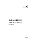
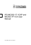
CellPipe 7230 Business Gateway 100V
series
7230 BG 1VE.C2000
QUICK INSTALLATION GUIDE
401-389-002
ISSUE 1
FEBRUARY 08
Alcatel, Lucent, Alcatel-Lucent and the Alcatel-Lucent logo are trademarks of Alcatel-Lucent. All other
trademarks are the property of their respective owners.
The information presented is subject to change without notice. Alcatel-Lucent assumes no responsibility for
inaccuracies contained herein.
Copyright © 2008 Alcatel-Lucent. All Rights Reserved.
Conformance statements
The device complies with Part 68 of the Federal Communications Commission (FCC) statements, Japan VCCI
Class B, and the requirements of the Council Directive 89/336/EEC on the Approximation of the laws of the
member states relating to Electromagnetic Compatibility and 72/23/EEC for electrical equipment used within
certain voltage limits and the Amendment Directive 93/68/EEC as stated in the CE Mark Declaration of
Conformance for EMI and Safety.
For detailled conformance statements refer to the User Manual.
QUICK
Overview
Purpose
This Quick Installation Guide provides information about how to install the
7230 BG 1Ve.C2000 at the customers premises, which may be apartment
blocks, hotels or office complexes.
This customer premises equipment (CPE) supports Ethernet-over-VDSL2 via
an Ethernet data link rated up to 100 Mb/s symmetric while simultaneously
supporting standard telephone service. Via its bridge functionality, it connects
any PC equipped with a 10BASE-T or 100BASE-TX network interface card
via a standard telephone cable to a VDSL switch. For this purpose, it provides:
•
•
•
1 VDSL port
1 port for telephony
1 LAN port (10/100BASE-TX).
Reason for revision
This version of the Quick Installation Guide is the first issue.
Hardware description
Package content
The package consists of the following components:
•
•
•
•
•
•
•
One 7230 BG 1Ve.C2000
4 Rubber foot pads
1 Standard telephone cable (2.1 m / 7 ft.)
1 Category 5 UTP network cable (1.8 m / 6 ft.)
1 AC power adapter
Quick Installation Guide
User Manual on CD-ROM.
Note: The AC-voltage is country-dependent, therefore the CellPipe
7230 BG 100V series is available with three different AC power adapters
(7230 BG 1Ve.C2000EUR, 7230 BG 1Ve.C2000JPN, 7230 BG
1Ve.C2000UKD).
....................................................................
1
....................................................................
Front and rear view
The front panel of the CPE provides several LEDs as system and port status
indicators. The rear panel includes ports for the VDSL line, for connection to a
telephone line, and a 10/100 Mb/s Ethernet connection to a PC. The rear panel
also includes the DC power input connector.
The following figures show the front panel with the LEDs and the rear panel
with the different ports.
Figure 1
Front and Rear Panels
LED indications for system and port status
The LEDs on the front panel indicate the following system and port status:
LED
Status
Description
System Status Indicators
POWER
On
Power is being supplied to the CPE
Off
No power is being supplied to the CPE
....................................................................
2
....................................................................
LED
Status
Description
DIAG
On
A failure has occurred during bootup diagnostics
(including self-test failure).
Flashing
A loopback test is in progress.
Off
at the same time, the FAIL LED is flashing.
A failure has been detected during operation.
Off
CPE is functioning properly
Off
CPE is functioning properly
Flashing
A failure has been detected during operation
FAIL
Port Status Indicators
VDSL
LAN
On
The VDSL port has a valid link with a VDSL switch,
without data transmission
Off
The VDSL port has no link with a VDSL switch
Slow
Flashing1
Flashing during training
Flashing
The VDSL port has a valid link with a VDSL switch and
is transmitting or receiving data
On
Ethernet port has a valid link with attached device
Off
Ethernet port has no link with other device
Flashing
CPE is transmitting or receiving data on this port
Notes:
1 The slow flashing state is a periodic on-off cycle of approximately once per second.
....................................................................
3
....................................................................
Install the CPE
When to use
Use this procedure to install the 7230 BG 1Ve.C2000, that means to make the
connections to the network, to the terminal equipment which may be a
telephone or a fax machine, to the PC and to the power supply, and to establish
a TCP/IP connection from the PC to the CPE. The following figure shows the
CPE with all external connections established. This will be described step by
step in the procedure below.
Figure 2
Overview about all external connections
System requirements
1.
2.
3.
4.
The CPE should be located in a cool dry place, with at least 5 cm (2 in.) of
space on all sides for ventilation. Place the CPE out of direct sunlight, and
away from heat sources or areas with a high amount of electromagnetic
interference.
For power supply, the CPE requires 12 V DC via the included AC power
adapter. The power adapter is designed for a 110/220 V AC connection.
The CPE is a plug-and-play unit and not need any configuration or
maintenance.
For Internet access, a PC with a 10/100 Mb/s Ethernet adapter card
installed is required. The PC must be configured for TCP/IP.
....................................................................
4
....................................................................
Related information
For detailed information about the CPE refer to the User Manual on the
attached CD-ROM.
Before you begin
Make sure that the package content is complete. Preserve original carton and
packaging material.
Procedure
.............................................................................................................................................
1
Connect one end of the attached standard telephone cable to the port on the
CPE which is labeled LINE. Connect the other end to the telephone wall outlet
providing the VDSL service.
.............................................................................................................................................
2
Connect a telephone or fax machine to the port on the CPE which is labeled
PHONE.
.............................................................................................................................................
3
Connect one end of the Category 5 UTP network cable to the LAN port on the
CPE and the other end to the port of the network interface on the PC.
.............................................................................................................................................
4
Connect the cord of the AC power adapter to the DC 12V power socket on the
CPE which is labeled POWER. Then plug the power adapter directly into the
AC power outlet.
Result: The LED marked POWER on the front panel is on.
.............................................................................................................................................
5
Make sure that the Ethernet port of your PC is correctly configured for DHCP.
For more details refer to Appendix B “Configuring the TCP/IP protocols on
the PC”.
.............................................................................................................................................
6
Establish the first connection to the ISP provider.
END OF STEPS
.............................................................................................................................................
....................................................................
5
....................................................................
....................................................................
6
A
Troubleshooting
Overview
Purpose
This Appendix provides guidance for troubleshooting. The CPE operation can
easily be monitored via the LED indicators to identify problems. The table
below describes common problems you may encounter and possible solutions.
Diagnosing
Symptom
Possible cause
POWER LED
does not light
up after power
on.
Power outlet, power
cord, or power adapter
may be defective.
LAN LED
does not light
up after
making a
connection.
Network interface
(e.g., a network
adapter card in the
attached computer),
network cable, or the
LAN port on the CPE
may be defect.
Solution
•
•
•
•
•
•
VDSL LED is
flashing
slowly after
making a
connection.
The cabling, or the
LINE port on the CPE
may be defect.
•
•
Check the power outlet by plugging in
another device that is functioning
properly.
Call the Customer Support Hotline or
return the device to the vendor.
Verify that the CPE and the computer are
powered on.
Make sure that the cable is plugged into
both, the CPE and the PC.
Verify that the proper cable type is used
and its length does not exceed specified
limits.
Check the network adapter in the PC and
the cable connections for possible defects.
Replace the defective adapter or cable if
necessary.
Verify that the CPE is powered on.
Make sure the cable is correctly plugged
into the VDSL line wall outlet and the
CPE connector labeled "LINE".
....................................................................
7
....................................................................
Symptom
Possible cause
Solution
A phone call
is not possible
The cabling, or the
PHONE port on the
CPE may be defect.
•
•
Verify that the CPE is powered on.
Make sure the cable is correctly plugged
into the telephone and the CPE connector
labeled "PHONE".
You cannot
connect to the
Internet
The PC may not be
configured as required
or the network adapter
driver may not fit.
•
Check that your PC is properly
configured for TCP/IP. (see: Configuring
the TCP/IP protocols on the PC page
9).
Make sure the correct network adapter
driver is installed for your operating
system. If necessary, try reinstalling the
driver.
Check that the speed of the network
adapter or duplex mode has not been
configured manually. We recommend to
set the adapter to auto-negotiation when
installing the network driver.
Did you establish your network
connection before starting your browser?
Verify your username and password entry
in the network connection tab.
•
•
•
•
....................................................................
8
B
Configuring the TCP/IP
protocols on the PC
Overview
Purpose
To connect the CPE to a PC through its Ethernet port, the PC must have an
Ethernet network adapter card installed, and be configured for the TCP/IP
protocol. Many service providers configure TCP/IP for client PC
automatically using a networking technology known as Dynamic Host
Configuration Protocol (DHCP). Other service providers may specify an IP
configuration (known as a static IP address), which must be entered manually.
Carry out the following steps to check that the computer’s Ethernet port is
correctly configured for DHCP.
Windows 95/98/NT
1.
2.
3.
4.
5.
6.
7.
8.
Click “Start/Settings/Control Panel.”
Click the “Network” icon.
For Windows NT, click the “Protocols” tab.
Select “TCP/IP” from the list of network protocols; this may include
details of adapters installed in your computer.
Click “Properties.”
Check the option “Obtain an IP Address.”
Click “OK” to close the TCP/IP Properties window.
Restart your computer.
Windows 2000
1.
2.
3.
4.
Click “Start/Settings/Network/Dial-up Connections.”
Click “Local Area Connections.”
Select “TCP/IP” from the list of network protocols.
Click on “Properties.”
....................................................................
9
....................................................................
5.
6.
7.
Select the option “Obtain an IP Address.”
Click “OK” to close the TCP/IP Properties window.
Restart your computer.
Windows XP
1.
2.
3.
4.
5.
6.
7.
Click “Start/Control Panel/Network Connections.”
(You may need to choose Settings before Control Panel, depending on
your Start Menu configuration.)
Right-click the “Local Area Connection” icon for the adapter you want to
configure, and choose “Properties.”
Highlight “Internet Protocol (TCP/IP).”
Click “Properties.”
Select the option “Obtain an IP address automatically” and “Obtain DNS
server address automatically.”
Click “OK” to close the TCP/IP Properties window.
Restart your computer.
Windows Vista
1.
2.
3.
4.
5.
6.
7.
8.
Click “Start/Control Panel/Network and Internet.”
(You may need to choose Settings before Control Panel, depending on
your Start Menu configuration.)
Click “Network and Sharing Center” then click “Manage network
connections.”
Right-click the “Local Area Connection” and choose Properties.
Select “Internet Protocol Version 4(TCP/IPv4).”
Click “Properties.”
Select “Obtain an IP address automatically” and “Obtain DNS server
address automatically.”
Click “OK” to close the TCP/IP Properties window.
Restart your computer.
Mac OS
1.
2.
3.
4.
Pull down the Apple Menu. Click “Control Panels” and select “TCP/IP.”
In the TCP/IP dialog box, verify that “Ethernet” is selected in the
“Connect Via:” field.
If “Using DHCP Server” is already selected in the “Configure” field, your
computer is already configured for DHCP. Otherwise, select “Using
DHCP Server” in the “Configure” field and close the window.
Another box will appear asking whether you want to save your TCP/IP
settings. Click “Save.”
....................................................................
10
....................................................................
5.
Your service provider will now be able to automatically assign an IP
address to your computer.
....................................................................
11
....................................................................
....................................................................
12