1
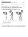
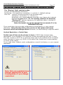
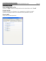
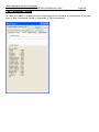
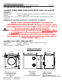
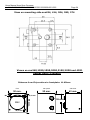
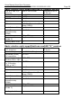
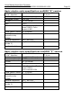
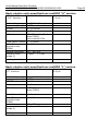
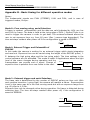
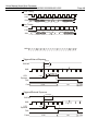
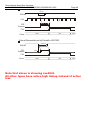
Digital Progressive Area-Scan Camera SVCam “CF” series CameraLink svs340, 424, 414, 204, 1020, 1050, 285, 2050, 2051, 2020, 274, 4021 and 625 Users Manual Version 3.1 SVS-VISTEK GmbH Muehlbachstr. 20 82229 Seefeld GERMANY Tel +49-(0)8152-99 85-0 E-Mail: [email protected] Fax +49-(0)8152-99 85-79 WEB: www.svs-vistek.com Last update 22.07.2009 Users Manual Area-Scan Cameras svs414/424/204/285/340/1020/1050/2050/2150/2020/4021/625 Page 2 Index Chapter 1 - Introduction ...................................................................................................................3 Chapter 2 – Pin out and Installation ... .......................................4 2.1. Unpacking ...................................................................................................4 2.2. Power supply …………...............................................................................................4 2.3. Trigger connector ....................................................................................................4 2.4 Camera Link connector ………………………………………………………............................................................5 2.5. Installation …………..........................................................................6 2.6. Available operation modes ..........................................................6 Chapter 3 - Technical Data ............................................................................................................7 3.0. Operation ...................................................................................7 3.1. CCD Sensor/2 tap –1 tap output .................................................................7 3.2. Signal conditioning ...................................................................8 3.3. Interfacing/ use of the “Convenient Cam” program ..........................8 3.4. Mechanical and optical issues .........................................................18 3.5. Basic electro optical characteristics of Cameras .................................21 3.6. Environmental Tests ..................................................................31 3.7 Spectral response curve ..................................................................32 3.8 Comments on camera temperature/“U” version with integrated fan …...35 3.9. Comments on COLOR Version ..........................................................36 Chapter 4 - Miscellaneous 4.0. Proven Interfacing to frame grabber .................................................37 4.1. Warranty Terms ..........................................................................38 Appendix A – Troubleshooting ..................................................................39 Appendix B - General Pixel and Line Timing .................................................40 Appendix C - Code Description for serial Camera Control Appendix D – For Camera Link Versions .................................43 .................................................49 Appendix E – SAFETY INSTRUCTIONS ..........................................................50 Users Manual Area-Scan Cameras svs414/424/204/285/340/1020/1050/2050/2150/2020/4021/625 Page 3 1. Introduction Thank you for purchasing a SVS-VISTEK product. We hope that you will be satisfied by our service. This camera uses CCD`s as optical image sensors. They feature low dark current and high speed readout. The SVS Compact Line cameras offer full image with one shot, combined with digital output (non interlaced, progressive scan cameras). Further, they feature an excellent S/N ratio at low prices. The exposure time can be adjusted in different ways. 3 operation modes are available to cover most applications in image processing and optical metrology. The following types are covered in this manual: svs340 1/3” CCD, 640 x480 Pixel, 10/12 Bit gray level resolution, approx. 250 frames/sec, monochrome and color version svs1020 2/3” CCD, 1000 x 1004 Pixel, 10 frames/sec, monochrome and color version Bit gray level resolution, approx. 71 svs1050 1/2” CCD, 1024 x 1024 Pixel, 12 frames/sec, monochrome and color version Bit gray level resolution, approx. 90 svs424 1/3” CCD, 640 x480 Pixel, 10 frames/sec, monochrome and color version Bit gray level resolution, approx. 116 svs414 1/2” CCD, 640 x480 Pixel, 12 Bit gray level resolution, approx. 30/60 frames/sec, monochrome and color version svs204 1/3” CCD, 1024 x 768 Pixel, 10 frames/sec, monochrome and color version Bit gray level resolution, approx. 50 svs285 2/3” CCD, 1360 x 1024 Pixel, 10/12 Bit gray level resolution, approx. 25 frames/sec, monochrome and color version svs2020 14.8 mm diagonal CCD, 1600 x 1200 Pixel, approx. 39 frames/sec, monochrome and color version 10 Bit gray level resolution, svs2050 2/3” CCD, 1600 x 1200 Pixel, frames/sec, monochrome and color version 12 Bit gray level resolution, approx. 50 svs2150 2/3” CCD, 1920 x 1080 Pixel, frames/sec, monochrome and color version 12 Bit gray level resolution, approx. 50 svs274 1 1/8” CCD, 1600 x 1200 Pixel, frames/sec, monochrome and color version 12 Bit gray level resolution, approx. 25 svs4021 21.5 mm diagonal CCD, 2048 x 2048 Pixel, up to 25 frames/sec, monochrome and color version svs625 2/3” CCD, 2456 x 2048 Pixel, frames/sec, monochrome and color version 10 Bit gray level resolution, 10 Bit gray level resolution, approx. 15 Users Manual Area-Scan Cameras svs414/424/204/285/340/1020/1050/2050/2150/2020/4021/625 Page 4 For more information on the color versions, please see chapter 3.9. If you need modifications, we will be glad to offer you a custom camera suitable to your application. Feel free to contact us at: SVS-VISTEK GmbH Muehlbachstr. 20, 82229 Seefeld Tel +49-(0)8152-99 85-0 Fax +49-(0)8152-99 85-79 E-mail [email protected] www.svs-vistek.com Users Manual Area-Scan Cameras svs414/424/204/285/340/1020/1050/2050/2150/2020/4021/625 Page 5 2.0 Pinout and Installation Warning The CCD camera is built with CMOS-LSI circuits. All internal electronics in the camera are sensitive to high voltage or electrostatic discharge. The camera can be destroyed if carelessly handled, so extreme care should be taken during set up and operation. Do not expose the sensor to a direct laser beam as this could damage the sensor! See Safety Instructions at Appendix E. Warranty will be void if not followed. 2.1 Unpacking - Camera - Power supply (if ordered/option) - User Manual - CD with “Convenient Cam” program Note that the “U” version has heat sink attached to the housing. To take advantage of the high frame rate a good airflow is highly recommended. If not done and operated in high temperature environment image distortions will be observed. CAMERA CAN BE DESTROYED IF YOU DON’T FOLLOW THESE INSTRICTION AND WARRANTY WILL BE VOID! 2.2 Power supply Male connector (Type TB3M Microswitch) PIN 1 +12V to +15 V DC PIN 2 Reserved (Do not connect) PIN 3 GND Current consumption: Svs1020,2020 and svs4021 (only) = 600 mA (typical) Peak current on “Power on” up to 2 Ampere! Current consumption increases rapidly when “partial scan” feature is used! All other models: 450 mA 2.3 Trigger connector TB 5M connector, 5 pin, is used to give an external trigger-input (min 5 V, galvanic decoupled) to the camera, if it is not done per frame grabber. Exsync input to trigger camera (optocoupler input) Pin 4: Tr - (Exsync GND) Pin 5: Tr + (Exsync min 5 V TTL) See outline in chapter 3.4 See chapter 2.6 Available operation modes Users Manual Area-Scan Cameras svs414/424/204/285/340/1020/1050/2050/2150/2020/4021/625 Page 6 2.4 “Camera Link” Connector 26 Pin connector MDR female (3 M): Base configuration with RS 232 communication Pin Name Direction Meaning Data Data Data Transmitterclock/PVAL Data Camera control (RS232) Camera control (RS232) Exsync Prin (not used) External camera clock NC 1 2 3 4 5 6 7 GND X 0X 1X 2XclkX3Ser TC+ Camera =>FG Camera =>FG Camera =>FG Camera =>FG Camera =>FG FG => Camera 8 SerTFG- Camera =>FG 9 10 11 12 13 14 15 16 17 18 19 20 CC1CC2+ CC3CC4+ GND GND X 0+ X 1+ X2+ Xclk+ X3+ SerTC- FG FG FG FG Camera =>FG Camera =>FG Camera =>FG Camera =>FG Camera =>FG FG => Camera 21 SerTFG+ Camera =>FG 22 23 24 25 26 CC1+ CC2CC3+ CC4GND FG FG FG FG => => => => => => => => Camera Camera Camera Camera Camera Camera Camera Camera Data Data Data Transmitterclock/PVAL Data Camera control (RS232) Camera control (RS232) Exsync Prin (not used) External camera clock NC All cameras have a “BASE” configuration according to Camera Link definition. However, the output of the Kodak 340, 1020, 1050,2020,2050,2150 and 4021 CCD are two tap sensors compared to cameras using Sony CCD. Only Sony ICX625 is also 2 tap. 2.5 Installation 1) Install camera in the desired location. You can use the ¼“ tripot adapter or use the 4 M3 holes in the adapter of the camera. Users Manual Area-Scan Cameras svs414/424/204/285/340/1020/1050/2050/2150/2020/4021/625 Page 7 2) Connect the power supply. If you have ordered a P/S connect it to the 3 Pin connector on the camera. If you use your own power supply (must be 12 V DC) make sure you connect it to Pin1 (+12 V) and Pin 3 (GND). If you – by mistake – supply line with GND pin the camera can be damaged! If power supply was ordered, do not modify it. Connect a Camera Link cable to your frame grabber. Please note that cable length should not exceed 10 m for theses camera (“F” version and higher clocked ). A REPEATER is available to extend cable length. Consult your local distributor! 2.6 Available Modes of Operation General: All modes are set by the serial interface which connects via Camera Link standard cable. The default factory setting is Freerunning using the internal microcontroller for exposure control: Mode 0. The Gain of the signal can be adjusted software wise by a factor of 2. Please note that noise also is amplified. Higher Gain is possible but not specified! The Gain default setting is 1.0. Mode 0: Freerunning using Microcontroller In this mode the camera creates all sync signals itself. The frame rate is adjusted to a maximum by factory default. There is no need to trigger the camera (by EXSYNC) in order to get data. The Exposure time can be set by using the serial Interface of the PC. The enclosed program allows the user to set the values. Exposure time can be changed online during operation. Mode 1: Triggered and using Pulse width of Exsync In this mode the camera is waiting for an external trigger which causes the integration and read out. The exposure time can be varied by the length of EXSYNC between the high going edge and the low going edge. The Time settings in the control menu are not activated. This mode is useful in applications where the light level of the scene changes during operation. A frame to frame variation is allowed. Trigger can be fed via Framegrabber (if supported) or by TTL into on TB 5 connector (see 2.3) Mode 2: Triggered and using Microcontroller The frame rate is determined by the number of Exsync pulses per time. With each positive transition (going high) the camera will readout a frame. The Exposure time is set as mentioned in Mode 0. The maximum exposure time is 65535 line durations, Minimum is 1 line duration. Trigger can be fed via Frame grabber (if supported) or by TTL(min 5 V) into on TB 5 connector (see 2.3) Exposure time can be changed online during operation. Users Manual Area-Scan Cameras svs414/424/204/285/340/1020/1050/2050/2150/2020/4021/625 Page 8 Software: The camera comes with “Convenient Cam” program allowing interactive access to above parameters. This software is available for WIN XP. However ConvCam 3.0 requires Micosoft .Net which can be installed with the software if not yet on the PC. The color version will come on request with free software algorithm which will allow processing of the color image in the PC. This must to be done in order to interpolate the colors for each pixel. Please note that no responsibility can be taken for the algorithm. It might be necessary to change the algorithm according to the application. See chapter 3.7. 3.0 Operation An easy logic allows control of the camera by different signals to achieve optimum image quality. 3.1 Sensors: • Sony: ICX 424, 414, ICX204 , ICX285,ICX 274 and ICX 625 • Kodak KAI 340M/C 640 x 480 Pixel • Kodak KAI 1020M/C 1000 x 1000 Pixel • Kodak KAI 1050M/C 1024 x 1024 Pixel • Kodak KAI 2020M/C 1600 x 1200 Pixel • Kodak KAI 2150M/C 1920 x 1080 Pixel • Kodak KAI 4021M/C 2048 x 2048 Pixel Note following cosmetic specs for Kodak CCD which have more resolution than VGA: Cluster allowed. Cluster may contain up to 10 Pixel out of PRNU spec. 8 cluster allowed Point defects: 10 dead Pixel allowed. More details are available in the Kodak spec sheet available at www.Kodak.com. Spectral range: 400 - 900 nm (B/W), COLOR version: RGB Bayer Mosaic Filter, see 3.7 Users Manual Area-Scan Cameras svs414/424/204/285/340/1020/1050/2050/2150/2020/4021/625 3.1.2 Page 9 Read out from CCD/svs340 ,625, 1020, 1050,2020, 2050, 2150, 4021 and 625 only The output for the “U“,”F” ,”H”and “R” version is as follows: 2 taps are read out and the right half of the image is mirrored starting at 1st line pixel #1025 through 2048 ( 4021). See image below. As a result either framegrabber or PC memory must reverse the 2nd half in order to get a complete image as it is for the “S” or “O” version. There the complete image is read out as usual with one tap CCD. 2 Tap output “F”, “U” ,”H”and “R” 1 Tap output “S” +”O”version A tap balancing dll for automatic tap balancuing ( for programming engineers) is available. 3.2 Signal conditioning The analog output of the sensor is conditioned by Correlated Double Sampling (CDS) for optimum S/N ratio.Dark level drift is compensated by an “auto zero” amplifier circuit and fed into a video ADC with 10, 12 or 14 bit resolution. (type dependend) Users Manual Area-Scan Cameras svs414/424/204/285/340/1020/1050/2050/2150/2020/4021/625 3.3 Interfacing/use of the “Convenient Cam” program Page 10 Before you start check version of the control software called Covenient Cam (ConvCam) program! svs1050,2050,2150, 625, 274 and 414 will ONLY work with ConvCam3.0 or higher! The camera can be operated in a free running mode as well as in a synchronized and triggered mode. An exposure control can be set by serial communication or by using the pulse width of the trigger signal (Exsync). For PC support a software disk, “Convenient Cam”, is enclosed which allows setting of parameters via a serial port. For OEMs the source code is available on request. A DLL is delivered with the program and MICROSOFT ® DOT NET Framework 2.0 is required is to get the “Convenient Cam 3.0” program working. See screen shot of the menu The camera can also be operated with any terminal program. See “Command Overview.doc” If you have installed the camera and connected power, you can install the program to do the first test. The program will fail to start if it can’t find the DLL! Check the Readme file and Load DLL in ConvCam menu. FIRST: Install the ConvCam program and THAN: You will have a) Already Dot Net on you PC or b) Make sure that a Internet connection is present during installation All cameras except svs1050,2050,2150,625, 274 and 414 can still work with ConvCam 2.6. See older version of this manual. Users Manual Area-Scan Cameras svs414/424/204/285/340/1020/1050/2050/2150/2020/4021/625 Page 11 The “Connection“ Folder The “Set Port No”: Tick always to “Enable Camera Link” for communication via Frame grabber. Load CameraLink DLL if communication fails in the beginning The serial Port (in case above does not work) Set COM port for serial control which will work with your frame grabber via Camera Link. Tick “enable serial port”. If you get error messages starting the software make sure that your camera is connected to the chosen port (usually com 3, 4, 5, 6, … due to Camera Link standard). You can change the port with the “COM:”-field if the Camera Link will not work immediately. (If supported by framegrabber manufacturer). Port info: can display framegrabber port used (If supported by framegrabber manufacturer) Users Manual Area-Scan Cameras svs414/424/204/285/340/1020/1050/2050/2150/2020/4021/625 Page 12 The “Main Features” Folder The program will identify the used camera type (top). And S/N number (bottom) The ”Exposure time“ field Exposure time: the exposure time can be set in µsec. The min exposure time is about 50 µsec (depending on the camera type and speed). The longest is about several seconds (triggered modes). Due to the internal timing of the camera the program will adjust the values to the appropriate values. Exposure time can also be expressed as “line time” because the minimum time set is the duration of one line. If you use this field the exposure time in µsec will change automatically and vice versa. The “Gain” and “Offset“ field The default gain setting is “1.0”. You may change the gain up to factor 3.0 (or higher) in steps of 1/10th. Note that the dark offset will increase and dynamic range will not be improved! For good image quality do not increase gain more than factor 2, because the noise is also amplified. “Gain value” allows finer adjustments than “gain factor”. “F”, “U” ,”H”and “R” version of svs1020,1050, 2020,2050,2150 and 4021: Note that the CCD has 2 outputs. Therefore there are a “right” and a “left” image half. If you use the slider both channels are amplified. However depending on the amplifications there might be different values necessary in order to make both channels equal. Fine tuning in “Gain Value” is necessary. There are about 768 possible steps to adjust. It is still possible to have 1-2 counts difference between both image halves. This is NOT a camera problem and must be adjusted by an experienced user. Same is true for the offset. Dark level offset adjustment is possible. Please note that factory adjustment is optimized for S/N ratio and sensitivity. You may lose dynamic range. Alter only if you operate at high temperatures like +40 °C. It can be altered for each channel separately. There is an ATOMATED Tap balancing dll, usually coming with the CD . Or download from FTP. Inquire for the download location The “Snapshot Botton” (svs625, 274, 414, 2050,2050,2150 only) Will read ONE image only if camera is set to “freerunning” or” triggered with internal expo control” mode. Users Manual Area-Scan Cameras svs414/424/204/285/340/1020/1050/2050/2150/2020/4021/625 Page 13 The “Frame Rate” field In “free Running” mode (default ex factory) you can adjust the framerate f Users Manual Area-Scan Cameras svs414/424/204/285/340/1020/1050/2050/2150/2020/4021/625 Page 14 The “Save Restore” folder The “Reset Camera” button If you have troubles during configuration, you can set the last saved configuration clicking this button (you could also switch power off and on and also and click on “read status” again). The “Save to EEPROM” button If you have configured your camera successfully you can save the actual configuration in the EEPROM of the micro controller. Every time the camera is connected to power it will start with this configuration. Ensure that your camera is running correctly before you click this button! Users Manual Area-Scan Cameras svs414/424/204/285/340/1020/1050/2050/2150/2020/4021/625 Page 15 The “Trigger Mode” folder “Free Running”, Mode 0 At the first installation it should be mode 0 (factory default). This means the camera is free running with maximum frame rate and exposure time is controlled by the internal micro controller. Exposure time can be set via serial communication (ConvCam.exe, see “Main Features). No further external signals. “Opto Triggered”, external exposure control, Mode 1 If you want to trigger the camera and determine the exposure time by the pulse width of Exsync, choose this mode. Then apply a Exsync signal at the appropriate pins e.g. on pins of TB 5 connector. The rising edge of the pulse the camera will start exposure time. The exposure time ends with the falling edge of Exsync. Please check the timing diagram in the appendix of this manual. “Opto Triggered”, internal exposure control, Mode 1 If you want to trigger the camera and determine the exposure time by the internal micro controller choose this mode. You still need to use the Exsync signal (min 5 V TTL) in order to trigger the camera (see “Trigger”-buttons below). It will initiate exposure by the rising edge of the pulse. Apply a Exsync signal at the appropriate pins e.g. on pins of TB 5 connector Please check the timing diagram in the appendix of this manual. “LVDS Triggered”, external exposure control, Mode 2 If you want to trigger the camera via framegrabber and use pulse width control controller then use this mode. Exposure time is set via Camera Link through you frame grabber. (Contact your frame grabber supplier for how to feed signal into the grabber). The framegrabber generates the pulse width of the exposure time. With the rising edge of the pulse the camera will start exposure time. The exposure time ends with the falling edge of Exsync. Users Manual Area-Scan Cameras svs414/424/204/285/340/1020/1050/2050/2150/2020/4021/625 Page 16 “LVDS Triggered”, internal exposure control, Mode 2 If you want to trigger the camera trigger the camera via framegrabber and use the convenient exposure time control of the micro controller then use this mode. You still can use the serial port for setting exposure time (see “Main features”-folder). Users Manual Area-Scan Cameras svs414/424/204/285/340/1020/1050/2050/2150/2020/4021/625 Page 17 The vertical (partial scan) and horizontal resolution Folders The “Binning” field: readout modes You can choose different resolutions No Binning: Full resolution: horizontal x 1, vertical x 1 (default setting) H2x V2x: Vertical 2x and Horizontal 2x at the same time: Resolution: horizontal x ½, vertical x ½, Sensitivity is 4x, pixel frequency is halved, max. frame rate is almost doubled. In case of “L”,”H”,”R” binning results in 2x sensivity. “Binning Off” sets the camera to full resolution either in vertical or horizontal resolution. Note: Horizontal can not be changed in increments. It is for INFORMATION only! If you need other binning mode configurations consult factory or your nearest distributor. Using binning with a color version of the camera will cause incorrect colors and strange effects! However, for fast focusing it might be useful. Vertical Resolution = Partial Scan Partial scan of lines can be chosen in steps of 19/32 lines (camera type dependend). As an example: The minimum number and starting point are 17 lines. The max. number is 2672. As a result the frame rate of the camera will be increased when resolution is lower e.g. 4008 x 1024 yields 9 fps. Partial scan is done starting in center of the imager. If you need other readout mode configurations consult the factory or your nearest distributor. Note that you probably have to change camera file of your framegrabber if you change resolution! Users Manual Area-Scan Cameras svs414/424/204/285/340/1020/1050/2050/2150/2020/4021/625 Page 18 Binning- and Decimation- modes for 14bit “CPC”- cameras ( 12 bit output): All BW-14Bit-cameras support vertical binning (1/2 vertical resolution). In horizontal direction decimation can be used: The BW-camera sends a DVAL-signal with ½ pixel clock frequency When DVAL-signal is enabled on the grabber only every second pixel in horizontal direction is grabbed. When vertical binning is enabled on the camera and DVAL-signal on the grabber the images look like 2x2 binned. Some color cameras support a decimation mode where every third line .5is readout from the sensor and the DVAL-signal from the camera masks out 2 of 3 pixels in horizontal direction (1/3 pixel frequency). When DVAL-signal is enabled on the grabber only every third pixel in horizontal direction is grabbed. The Bayer pattern color information is preserved with one third horizontal and vertical resolution. Frame readout speed is increased by factor 2.5 (circa) Cameras with decimation mode: SVS16000CxxCPC and SVS2020CxxCPC. All other color 14-bit cameras support vertical binning like the BW-cameras To get the full resolution from the 14 bit cameras DVAL-signal has to be disabled on the grabber! Users Manual Area-Scan Cameras svs414/424/204/285/340/1020/1050/2050/2150/2020/4021/625 The Data Folder Save configuration to file Allows to “Save” different configurations and upload them with “Load” Create Log file Creates a log file in a directory (e.g. program/svs-vistek/convcam) It store all changes made to the camera during operation period. Close Logfile Stops the command protocol. Page 19 Users Manual Area-Scan Cameras svs414/424/204/285/340/1020/1050/2050/2150/2020/4021/625 Page 20 The Terminal Folder In case you want to make a serial connection to the camera via CameraLink you can type in the commands listed in Appendix C Of this manual. Users Manual Area-Scan Cameras svs414/424/204/285/340/1020/1050/2050/2150/2020/4021/625 Page 21 The Pixel clk folder Or following model the pixel clk can be adjusted: All version using 14 bit ADC and an order code like svs10250MTHCPC ( example) There are: svs340, svs1050, 2050, 2051 Pixel clk can be up to 80 MHz depending on model.( not shown here). Users Manual Area-Scan Cameras svs414/424/204/285/340/1020/1050/2050/2150/2020/4021/625 Page 22 3.4 Mechanical and optical issues svs4021,1050,2050,2150,2020,1020, 625 and svs340 (ONLY) Camera size: Weight: Front plate with C-Mount 50 x 55 x 43mm (without connectors and lens and heatsink) Approx. 200 Gram M 42 x 1 threads and C mount adapter for svs4021.All others: Distance from Chip surface to frontplate: 11.65mm NOTE: THE C-MOUNT ADAPTER of svs4021 IS INTENDED FOR EASY SETUP. However it might cause dark edges due to a loss of light in the corners. This is known and not a fault of the camera. We recommend use of solutions from Schneider, SILL, or LINOS who offer interfaces to M42 thread. Sometime C-Mounts work with focal length longer than 50mm. Do not use lenses which are intended for CCDs smaller than 1 “! svs424, 414, 204, 285 and 274 Camera size: 50 x 55 x 35mm (without connectors and lens) Weight: Approx. 200 Gram Front plate with C-Mount adapter Views on Camera: rear panel side view 50 mm. 50 mm. 35 mm. 1 42,42 mm. 4 1 55 mm. 3 2 55 mm. C-Mount 3 5 2 M3 front 42,42 mm. MDR 26 female Connector Sync and Dataserial LVDS see Listing on 2.4..2 Mating connector: 3M Part.-Nr of connector 10126-6000EL Part .-Nr of hood: 10326-A200-00 Power Connector: Pin 1:+12V Pin 3: GND Pin 2: Reserved Mating connector :Switchcraft TA3F Trigger Connector: Pin 4: TTL –(GND) Pin 5:TTL + Pin 1,2,3 : Do Not Connect Mating connector :Switchcraft TA 5F Users Manual Area-Scan Cameras svs414/424/204/285/340/1020/1050/2050/2150/2020/4021/625 Page 23 Users Manual Area-Scan Cameras svs414/424/204/285/340/1020/1050/2050/2150/2020/4021/625 Page 24 View on mounting side svs424, 414, 204, 285, 274 Views on svs340,1020,1050,2050,2150,2020 and 4021 except front (C-Mount) Distance from Chip surface to frontplate: 11.65mm M3 50 mm. 43 mm. 4 1 3 2 55 mm. M42 3 5 42,42 mm. side view 1 50 mm. rear panel 2 front 42,42 mm. 55 mm. Users Manual Area-Scan Cameras svs414/424/204/285/340/1020/1050/2050/2150/2020/4021/625 Page 25 M42 x 1 to C-Mount adapter is a standard when svs4021 is delivered Views on svs4021 “U” version and svs625 only front rear panel 50 mm. 50 mm. 43 mm 43 mm side view 43 mm 16.5 4 55 mm. 1 55 mm. C-Mount 3 5 2 1 42,42 mm. 3 2 M3 42,42 mm. Distance from Chip surface to frontplate: 11.65mm View on mounting side of svs340,1020,1050,2050,2150,2020 and 4021 Users Manual Area-Scan Cameras svs414/424/204/285/340/1020/1050/2050/2150/2020/4021/625 3.5 Basic electro-optic specifications of camera svs424 CCD ICX 424 1 1/3” Interline Readout frequency Framerate (max) Framerate (2 x 2 Binning) OFFSET 480 x 640 Pixel 1 x 48 MHz 116 FPS 336 FPS Gain 1 to 2 Pixelsize 7.4 x 7.4 µm Ca. 10 counts S/N ratio 8.5 Bit (Saturation/Dark Noise (RMS)) Fixed Pattern Noise +/- 2 counts Photo Response Nonuniformity (PRNU) Spectral response Exposure time (mode 2) Leading dark lines +/- 10 % 380 – 950 nm 50 µSec – 2 Sec 1 Basic electro-optic specifications of camera svs414 CCD ICX 414 1 1/2” Interline Readout frequency Framerate (max) Framerate (2 x 2 Binning) OFFSET 480 x 640 Pixel 20 or 40 MHz selectable 30 or 60 selectable FPS 93 or 187 selectable FPS Gain 1 to 2 Ca. 10 counts S/N ratio 10.5 Bit (Saturation/Dark Noise (RMS)) Fixed Pattern Noise +/- 2 counts Photo Response Nonuniformity (PRNU) Spectral response Exposure time (mode 2) Leading dark lines +/- 10 % 380 – 950 nm 50 µSec – 2 Sec 1 Pixelsize 9.9 x 9.9 µm Page 26 Users Manual Area-Scan Cameras svs414/424/204/285/340/1020/1050/2050/2150/2020/4021/625 Basic electro-optic specifications of camera svs204 CCD ICX 204 1/3” Interline Readout frequency Framerate (max) Framerate (2 x 2 Binning) OFFSET 1024 x 768 Pixel 1 x 48 MHz 50 FPS 150 FPS Gain 1 to 2 Pixelsize 4.65 x 4.65 µm Ca. 10 counts S/N ratio 8 Bit (Saturation/Dark Noise (RMS)) Fixed Pattern Noise +/- 2 counts Photo Response Nonuniformity (PRNU) Spectral response Exposure time (mode 2) Leading dark lines +/- 10 % 380 – 950 nm 50 µSec – 2 Sec monochrome 1 Basic electro-optic specifications of camera svs285 “F” CCD ICX 285 2/3” Interline Readout frequency Framerate (max) Framerate ( 2 x 2 Binning) OFFSET 1360 x 1024 Pixel 1 x 48 MHz 25 FPS 62 FPS Gain 1 to 2 Ca. 10 counts S/N ratio 8.5 Bit (Saturation/Dark Noise (RMS)) Fixed Pattern Noise +/- 2 counts Photo Response Nonuniformity (PRNU) Spectral response Exposure time (mode 2) Leading dark lines +/- 10 % 380 – 950 nm 50 µSec – 2 Sec 1 Pixelsize 6.54 x 6.54 µm Page 27 Users Manual Area-Scan Cameras svs414/424/204/285/340/1020/1050/2050/2150/2020/4021/625 Basic electro-optic specifications of camera svs285 “U” CCD ICX 285 2/3” Interline Readout frequency Framerate (max) OFFSET 1360 x 1024 Pixel Gain 1 to 2 Pixelsize 6.54 x 6.54 µm 1 x 64 MHz 33 FPS Ca. 10 counts S/N ratio 10.5 Bit (Saturation/Dark Noise (RMS)) Fixed Pattern Noise +/- 2 counts Photo Response Nonuniformity (PRNU) Spectral response Exposure time (mode 2) Leading dark lines +/- 10 % 380 – 950 nm 50 µSec – 2 Sec 11 Basic electro-optic specifications svs340 “U” version CCD KAI 340 D 1/3” Interline Readout frequency Framerate (max) Full resolution Framerate (max) Window 228 x 164 Framerate (max) 2 x 2 Binning ( 320 x 240 ) OFFSET 640 x 480 Pixel Gain 1 to 2 2 x 50 MHz (2 tap) 250 FPS 1.724 FPS 465 FPS Ca. 10 counts S/N ratio 8.5 Bit (Saturation/Dark Noise (RMS)) Fixed Pattern Noise +/- 2 counts Photo Response Nonuniformity (PRNU) Spectral response Exposure time (mode 2) +/- 10 % Leading dark lines 2 380 – 950 nm 30 µSec – 2 Sec Pixelsize 7.4 x 7.4 µm Page 28 Users Manual Area-Scan Cameras svs414/424/204/285/340/1020/1050/2050/2150/2020/4021/625 Basic electro-optic specifications svs340 “R” version CCD KAI 340 D 640 x 480 Pixel 1/3” Interline Readout frequency 2 x 80 MHz (2 tap) Framerate (max) 400 FPS Full resolution Framerate (max) 2 x 2 Binning ( 320 x 240 ) OFFSET 650 FPS Gain 1 to 2 Pixelsize 7.4 x 7.4 µm Ca. 40 counts @12 bit S/N ratio 8.5 Bit (Saturation/Dark Noise (RMS)) Fixed Pattern Noise +/- 8 counts Photo Response Nonuniformity (PRNU) Spectral response Exposure time (mode 2) +/- 10 % Leading dark lines 4 380 – 950 nm 58 µSec – 8 Sec Basic electro-optic specifications svs1020 “U” version CCD KAI 1020 1 1/4” Interline Readout frequency Framerate (max) OFFSET 1000 x 1000 Pixel 2 x 50 MHz (2 taps) 71 FPS Ca. 10 counts Gain 1 to 2 S/N ratio 8 Bit (Saturation/Dark Noise (RMS)) Color version 8 Bit Fixed Pattern Noise +/- 2 counts Photo Response Nonuniformity (PRNU) Spectral response Exposure time (mode 2) Leading dark lines +/- 10 % 380 – 950 nm 50 µSec – 1.3 Sec 2 Pixelsize 7.4 x 7.4 µm Page 29 Users Manual Area-Scan Cameras svs414/424/204/285/340/1020/1050/2050/2150/2020/4021/625 Basic electro-optic specifications svs1050 “L” version CCD KAI 1050 1024 x 1024 Pixel Pixelsize 5.5 x 1/2” Interline 5.5 µm Readout frequency Up to 2 x 48MHz (2 taps) Framerate (max) 68 FPS OFFSET Ca. 40 counts @12 bit Gain 1 to 2 S/N ratio 9 Bit (Saturation/Dark Noise (RMS)) Fixed Pattern Noise +/- 8 counts Photo Response Nonuniformity (PRNU) Spectral response Exposure time (mode 2) +/- 10 % Leading dark lines 10 380 – 950 nm 48 µSec – 8 Sec Basic electro-optic specifications svs1050 “H” version CCD KAI 1050 1024 x 1024 Pixel Pixelsize 5.5 x 1/2” Interline 5.5 µm Readout frequency Up to 2 x 64MHz (2 taps) Framerate (max) 90 FPS OFFSET Ca. 40 counts @12 bit Gain 1 to 2 S/N ratio 9,5 Bit (Saturation/Dark Noise (RMS)) Fixed Pattern Noise +/- 8 counts Photo Response Nonuniformity (PRNU) Spectral response Exposure time (mode 2) +/- 10 % Leading dark lines 10 380 – 950 nm 48 µSec – 8 Sec Page 30 Users Manual Area-Scan Cameras svs414/424/204/285/340/1020/1050/2050/2150/2020/4021/625 Basic electro-optic specification svs2020 “S” version CCD KAI 2020 1 1/4” Interline Readout frequency Framerate (max) OFFSET 1600 x 1200 Pixel Gain 1 to 2 Pixelsize 7.4 x 7.4 µm 1 x 40 MHz (1 tap) 18.5 FPS Ca. 10 counts S/N ratio 9 Bit (Saturation/Dark Noise (RMS)) Color version 8 Bit Fixed Pattern Noise +/- 2 counts Photo Response Nonuniformity (PRNU) Spectral response Exposure time (mode 2) +/- 10 % Leading dark lines 2 380 – 950 nm 60 µSec – 4.7 Sec Basic electro-optic specifications svs2020 “F” version CCD KAI 2020 1 1/4” Interline Readout frequency Framerate (max) OFFSET 1600 x 1200 Pixel Gain 1 to 2 2 x 40 MHz (2 taps) 30 FPS Ca. 10 counts S/N ratio 9 Bit (Saturation/Dark Noise (RMS)) Color version 8 Bit Fixed Pattern Noise +/- 2 counts Photo Response Nonuniformity (PRNU) Spectral response Exposure time (mode 2) +/- 10 % Leading dark lines 2 380 – 950 nm 75 µSec – 1.6 Sec Pixelsize 7.4 x 7.4 µm Page 31 Users Manual Area-Scan Cameras svs414/424/204/285/340/1020/1050/2050/2150/2020/4021/625 Basic electro-optic specifications svs2020 “U” version CCD KAI 2020 1 1/4” Interline 1600 x 1200 Pixel Pixelsize 7.4 x 7.4 µm Readout frequency 2 x 50 MHz (2 taps) Framerate (max) 40 FPS OFFSET Ca. 10 counts Gain 1 to 2 S/N ratio 8 Bit (Saturation/Dark Noise (RMS)) Color version 8 Bit Fixed Pattern Noise +/- 2 counts Photo Response Nonuniformity (PRNU) Spectral response Exposure time (mode 2) +/- 10 % Leading dark lines 2 380 – 950 nm 50 µSec – 1.3 Sec Basic electro-optic specifications svs2050 “L” version CCD KAI 2050 2/3” Interline 1600 x 1200 Pixel Readout frequency Up to 48 MHz (2 taps) Framerate (max) 39 FPS OFFSET Ca. 10 counts Gain 1 to 2 S/N ratio 10 Bit (Saturation/Dark Noise (RMS)) Fixed Pattern Noise +/- 8 counts Photo Response Nonuniformity (PRNU) Spectral response Exposure time (mode 2) +/- 10 % Leading dark lines 10 380 – 950 nm 48 µSec – 8 Sec Pixelsize 5.5 x 5.5 µm Page 32 Users Manual Area-Scan Cameras svs414/424/204/285/340/1020/1050/2050/2150/2020/4021/625 Basic electro-optic specifications svs2050 “H” version CCD KAI 2050 2/3” Interline 1600 x 1200 Pixel Pixelsize 5.5 x 5.5 µm Readout frequency Up to 64 MHz (2 taps) Framerate (max) 53 FPS OFFSET Ca. 10 counts Gain 1 to 2 S/N ratio 9,5 Bit (Saturation/Dark Noise (RMS)) Fixed Pattern Noise +/- 8 counts Photo Response Nonuniformity (PRNU) Spectral response Exposure time (mode 2) +/- 10 % Leading dark lines 10 380 – 950 nm 48 µSec – 8 Sec Basic electro-optic specifications svs2150 “L” version CCD KAI 2150 2/3” Interline 1980 x 1080 Pixel Readout frequency Up to 48 MHz (2 taps) Framerate (max) 36 FPS OFFSET Ca. 10 counts Gain 1 to 2 S/N ratio 10 Bit (Saturation/Dark Noise (RMS)) Fixed Pattern Noise +/- 2 counts Photo Response Nonuniformity (PRNU) Spectral response Exposure time (mode 2) +/- 10 % Leading dark lines 10 380 – 950 nm 58 µSec – 8 Sec Pixelsize 5.5 x 5.5 µm Page 33 Users Manual Area-Scan Cameras svs414/424/204/285/340/1020/1050/2050/2150/2020/4021/625 Basic electro-optic specifications svs2150 “H” version CCD KAI 2150 2/3” Interline 1980 x 1080 Pixel Pixelsize 5.5 x 5.5 µm Readout frequency Up to 64 MHz (2 taps) Framerate (max) 51FPS OFFSET Ca. 40 counts@12 bit Gain 1 to 2 S/N ratio 9,5 Bit (Saturation/Dark Noise (RMS)) Color version 8 Bit Fixed Pattern Noise +/- 8 counts Photo Response Nonuniformity (PRNU) Spectral response Exposure time (mode 2) +/- 10 % Leading dark lines 10 380 – 950 nm 58 µSec – 8 Sec Basic electro-optic specifications of camera svs274 CCD ICX 285 2/3” 1600 x 1200 Pixel Interline Readout frequency 1 x 64 MHz Framerate (max) 25 FPS OFFSET Ca. 40 counts@ 12 bit Gain 1 to 2 S/N ratio 8,5 Bit (Saturation/Dark Noise (RMS)) Fixed Pattern Noise +/- 8 counts Photo Response Nonuniformity (PRNU) Spectral response Exposure time (mode 2) Leading dark lines +/- 10 % 380 – 950 nm 50 µSec – 2 Sec 1 Pixelsize 6.54 x 6.54 µm Page 34 Users Manual Area-Scan Cameras svs414/424/204/285/340/1020/1050/2050/2150/2020/4021/625 Basic specifications of camera svs4021 “S” version CCD KAI 4021 1” Interline Readout frequency Framerate (max) OFFSET 2048 x 2048 Pixel Gain 1 to 2 Pixelsize 7.4 x 7.4 µm 1 x 40 MHz (1 tap) 8 FPS Ca. 10 counts S/N ratio 9 Bit (Saturation/Dark Noise (RMS)) Color version 8 Bit Fixed Pattern Noise +/- 2 counts Photo Response Nonuniformity (PRNU) Spectral response Exposure time (mode 2) Leading dark lines +/- 10 % 380 – 950 nm 120 µSec – 9.4 Sec 11 Basic electro-optic specifications svs4021 “F” version CCD KAI 4021 1 1/4” Interline Readout frequency Framerate (max) OFFSET 2048 x 2048 Pixel Gain 1 to 2 2 x 40 MHz (2 taps) 15 FPS Ca. 10 counts S/N ratio 9 Bit (Saturation/Dark Noise (RMS)) Color version 8 Bit Fixed Pattern Noise +/- 2 counts Photo Response Nonuniformity (PRNU) Spectral response Exposure time (mode 2) Leading dark lines +/- 10 % 380 – 950 nm 60 µSec – 4.7 Sec 11 Pixelsize 7.4 x 7.4 µm Page 35 Users Manual Area-Scan Cameras svs414/424/204/285/340/1020/1050/2050/2150/2020/4021/625 Basic electro-optic specifications svs4021 “U” versions CCD KAI 4021 1 1/4” Interline Readout frequency Framerate (max) OFFSET 2048 x 2048 Pixel Gain 1 to 2 2 x 48 MHz (2 taps) 20 FPS Ca. 10 counts S/N ratio 8 Bit (Saturation/Dark Noise (RMS)) Color version 8 Bit Fixed Pattern Noise +/- 2 counts Photo Response Nonuniformity (PRNU) Spectral response Exposure time (mode 2) Leading dark lines +/- 10 % 380 – 950 nm 50 µSec – 1 Sec 11 Pixelsize 7.4 x 7.4 µm Page 36 Users Manual Area-Scan Cameras svs414/424/204/285/340/1020/1050/2050/2150/2020/4021/625 Page 37 Basic electro-optic specifications svs4021 “H” versions CCD KAI 4021 1 1/4” Interline Readout frequency Framerate (max) OFFSET 2048 x 2048 Pixel Gain 1 to 2 Pixelsize 7.4 x 7.4 µm up to 2 x 64 MHz (2 taps) 25 FPS Ca. 40 counts@12 bit S/N ratio 9,5 Bit (Saturation/Dark Noise (RMS) Fixed Pattern Noise +/- 8 counts Photo Response Nonuniformity (PRNU) Spectral response Exposure time (mode 2) Leading dark lines +/- 10 % 380 – 950 nm 82 µSec – 8 Sec 8 Basic specifications of camera svs4021 “12 BIT-S” version CCD KAI 4021 1” Interline Readout frequency Framerate (max) OFFSET 2048 x 2048 Pixel Gain 1 to 2 1 x 20 MHz (1 tap) 4 FPS Ca. 10 counts S/N ratio 10.5 Bit (Saturation/Dark Noise (RMS)) Color version 8 Bit Fixed Pattern Noise +/- 2 counts Photo Response Nonuniformity (PRNU) Spectral response Exposure time (mode 2) Leading dark lines +/- 10 % 380 – 950 nm 240 µSec – 10 Sec 11 Pixelsize 7.4 x 7.4 µm Users Manual Area-Scan Cameras svs414/424/204/285/340/1020/1050/2050/2150/2020/4021/625 Page 38 Basic electro-optic specifications svs625 CCD ICX625 2/3“ Interline Readout frequency Framerate (max) OFFSET 2456 x 2045 Pixel Gain 1 to 2 S/N ratio 8.5 Bit (Saturation/Dark Noise (RMS)) Pixelsize 3.45 x 3.45 µm 2 x 50 MHz ( 2 taps) 15 FPS Ca. 10 counts Fixed Pattern Noise +/- 2 counts Photo Response Nonuniformity (PRNU) Spectral response Exposure time (mode 2) Leading dark lines +/- 10 % 380 – 950 nm 50 µSec – 8 minutes 13 3.6 Environmental Testing 3.6.1 Europe The camera is CE tested and the rules of EN 50022-2 apply. 3.6.2 USA and Canada I. Labeling requirements: This device complies with part 15 of the FCC Rules. Operation is subject to the following two conditions: (1) This device may not cause harmful interference, and (2) this device must accept any interference received, including interference that may cause undesired operation. II. Information to the user: Note: This equipment has been tested and found to comply with the limits for a Class A digital device, pursuant to part 15 of the FCC Rules. These limits are designed to provide reasonable protection against harmful interference when the equipment is operated in a commercial environment. This equipment generates, uses, and can radiate radio frequency energy and, if not installed and used in accordance with the instruction manual, may cause harmful interference to radio communications. Operation of this equipment in a residential area is likely to cause harmful interference in which case the user will be required to correct the interference at his own expense. Camera complies with FCC Form 47 Rules. It is necessary to use a shielded power supply cable which has GND contact to the camera housing. This is essential for any use. If not done and camera is destroyed due to Radio magnetic Interference (RMI) WARRANTY is void! If not destroyed increased noise level will be observed. Users Manual Area-Scan Cameras svs414/424/204/285/340/1020/1050/2050/2150/2020/4021/625 Page 39 Operating temperature Spec: -10 to +40°C. In order to keep dark current low. To achieve 9 optical Bits, operation at 25° max. is recommended. Shock is tested about 30 g in 6 ms. Vibration test is 10 g in 6 ms. Power: US/UK and European line adapter can be delivered. Otherwise use +12V DC with filtered and stabilized power supply. RoHS: All cameras comply with the recommendation of the European Union concerning RoHS Rules. 3.7 Spectral response curves Mono Version svs340/1020/1050/2050/2150/2020/2474021/424/625/414 and 204 All Color Version 1.0 1.0 0.9 0.8 0.7 Relative response Relative resp onse 0.8 0.6 0.5 0.4 0.3 0.6 0.4 0.2 0.2 0.1 0.0 400 0.0 500 600 700 800 Wavelength [nm] svs285 monochrome 900 1000 400 450 500 550 Wavelength [nm] 600 650 700 Users Manual Area-Scan Cameras svs414/424/204/285/340/1020/1050/2050/2150/2020/4021/625 Page 40 3.7. Comments on camera temperature/ “U” version Higher case temperature is noticed for e.g. svs625 and svs4021 version. There is no need to worry because camera has been tested at higher temperature than specified (40 °C). However some components inside like CCD, ADC, drivers are pushed to their limits. In order to take advantage of the speed of the “U” ( Ultra High Speed” version) it must be operated with forced air cooling. It means a gentle airflow not causing vibrations! This will help to extend life time of the camera Note that Warranty will be void if you don’t follow these instruction for “U” +”H” version (svs4021 ONLY !!)! Recommended setup: Recommended Airflow for "U" Type of cameras (One air stream is sufficient) Fan 05.07.05 SVS-VISTEK offers a version with integrated fan on the heatsink. See next page Users Manual Area-Scan Cameras svs414/424/204/285/340/1020/1050/2050/2150/2020/4021/625 Page 41 Technical Note on e.g. svs4021XUCP- K1 with fan Camera must be operated with running fan only. The specification of the fan is as follows: - Dimensions as per camera drawing Expected life time of fan 50.000 hrs Operating temperature –10 to +40°C Supply of fan12 V, 90 mA Cooling power 1.5 K/W Flow volume 150l/Min 2 wires: Red=12 V, Blk=GND , length 30 cm Position of wire can be changed front rear panel side view 50 mm. 46 mm 46 mm 46 mm 20 1 42,42 mm. 4 1 55 mm. 3 2 55 mm. 3 5 2 M3 42,42 mm. Caution! To avoid damage of the fan cooler following instructions must be observed: NEVER should pressure be exerted on the central fan plate or on the rotor wing since this could result in damage to the bearing system and in irreparable destruction of the fan cooler. Non compliance with these handling instructions will result that warranty of the camera is VOID! Users Manual Area-Scan Cameras svs414/424/204/285/340/1020/1050/2050/2150/2020/4021/625 3.8 Comments on COLOR Version Page 42 If you have purchased a COLOR version of this camera, please note the following: In all electrical terms the camera is identical to the black and white versions. The output is parallel or Camera Link but the color pixels are transferred in series from the camera. The camera uses a CCD which has a color mosaic filter. This filter is called "Bayer" filter named after the person who invented it. It has a pattern on the lines which alternates as follows: E.g.:First line: Second line: RGRGRG.... and so on. (R=RED, B=BLUE, G=GREEN) GBGBGB.... and so on. Please note that about half of the pixels are green, a quarter red and a quarter blue. This is due to the maximum sensitivity of the human eye at about 550 nm (green). Because this camera is a single chip camera it is necessary to use an algorithm which interpolates those colors which are "not known" by the specific pixel. E.g. the red pixel does not have information of green and blue components. This means that the performance of the image depends on the software used. Please be aware that it is not possible to incorporate the algorithm into the camera so easily. Unlike NTSC/PAL cameras there is no hardware chip available which can do that for such large images. The user has the advantage to alter the colors depending on his needs. Thus the color image must be processed in the PC. A color source code is available on request. We offer a complete set for a system setup containing camera, cable, power supply, frame grabber and software to help solving your applications. If you have questions do not hesitate to contact us or your local dealer. Users Manual Area-Scan Cameras svs414/424/204/285/340/1020/1050/2050/2150/2020/4021/625 4.0 Proven Interfacing to Frame grabbers Page 43 These Frame grabbers have been adapted to cameras mentioned in this manual successfully: EURESYS : Grablink Value/Expert/Express Dalsa/CORECO : PC-CamLink X64 CameraLink/ X64 I-PRO Matrox: Meteor II, Mikotron: Inspecta III/IV Matrix Vision : Titan CL Active Silica : Phoenix Silicon Software : Micro Enable III National Instruments : Bitflow: Helios , Solios 1426,148,1429 Neon-CL, Karbon-CL Epix: Strampe: Vision Box Please check individual camera types with framegrabber manufacturer ! Users Manual Area-Scan Cameras svs414/424/204/285/340/1020/1050/2050/2150/2020/4021/625 4.1. Warranty Terms Page 44 Standard products warranty and adjustment. Seller warrants that the article to be delivered under this order will be free from detects in material and workmanship under normal use and service for a period of TWO years from date of shipment. The liability of Seller under this warranty is limited solely to replacing or repairing or issuing credit (at the discretion fo Seller) for such products that become defective during the warranty period. In order to permit Seller to properly administer this warranty, Buyer shall notify Seller promptly in writing of any claims,; provide Seller with an opportunity to inspect and test the products claimed to be detective. Such inspection may be on customer’s premises or Seller may request return of such products at customer’s expense. Such expense will subsequently be reimbursed to customer if the product is found to be defective and Buyer shall not return any product without prior return authorization from Seller. If a returned product is found to be out of warranty or found to be within the applicable specification, Buyer will have to pay an evaluation and handling charge, independent of possible repair and/or replacement costs. Seller will notify Buyer of the amount of said evaluation and handling charges at the time the return authorization is issued. Seller will inform Buyer of related repair and/or replacement costs and request authorization before incurring such costs. Buyer shall identify all returned material with Sellers invoice number, under which material has been received. If more than one invoice applies, material has to be clearly segregated and identified by applicable invoice numbers. Adjustment is contingent upon Sellers examination of product, disclosing that apparent defects have not been caused by misuse, abuse, improper installation of application, repair, alteration, accident or negligence in use, storage, transportation or handling. In no event shall Seller be liable to Buyer for loss of profits, loss of use, or damages of any kind based upon a claim for breach of warranty. Development Product Warranty. Developmental products of Seller are warranted to be free from defects in materials and workmanship and to meet the applicable preliminary specification only at the time of receipt by Buyer and for no longer period of time in all other respects the warranties made above apply to development products. The aforementioned provisions do not extend the original warranty period of any article which has been repaired or replaced by Seller. If Warranty Label of camera is broken Warranty is void! SELLER MAKES NO OTHER WARRANTIES; EXPRESS OR IMPLIED; AND SPECIFICALLY; SELLER MAKES NO WARRANTY OF MERCHANTABILITY OF FITNESS FOR PARTICULAR PURPOSE. Users Manual Area-Scan Cameras svs414/424/204/285/340/1020/1050/2050/2150/2020/4021/625 Page 45 Appendix A - Troubleshooting Problem: Camera does not respond to light Solution: Please execute following steps Check if camera is in mode 0).Thus: Freerunning with serial exposure ctrl . When done, check with “Convenient Cam “program if you can read back any data from the camera like : Mode, type of CCD, exposure time settings and so on. If Mode 0 ) works check the signals of the camera in the desired operation mode like 1) or 2). In these modes check if the Exsync signal is present. Please note that a TTL signal must be fed to the trigger connector if it does not come from the framegrabber (LVDS type). The typical signal swing must be about 5V. Below such level the drivers in the camera will not work. If you use a TTL level signal fed to the TB 5 connector check the quality and swing. If these signals are not there or don’ t have the right quality the camera can not read out any frame ( mode 1 and 2). Beware of spikes on the signal !! Problem: lmage is present but distorted: Solution: Check the camera configuration file of your framegrabber. Check number of “front- and back porch “ pixel. Wrong numbers in configuration file can cause sync problems. Check if your framegrabber can work with the data rate of the camera. Problem: The image of a color version camera looks ”ugly” or false colors appear. Solution: If the raw image looks OK check the camera file to see if the pixels need to be shifted by either one pixel or one line. The image depends on the algorithm used. If the algorithm is starting with the wrong pixel such effects appear. Problem: The colors of a color version are not perfect especially when using a halogen light. Solution: Halogen light contains strong portions of IR radiation. Use cut off filters at around 730 nm like Schott KG 3 to prevent IR radiation reaching the CCD. Problem: No serial communication is possible between the camera and the PC Camera Link) Solution: Use “ load camera DLL” and try again. Users Manual Area-Scan Cameras svs414/424/204/285/340/1020/1050/2050/2150/2020/4021/625 Page 46 TROUBLESHOOTING REQUEST LIST V1.2 Dear valued customer, In order to help you with your camera and any interfacing problems we request that you fill in a description of your problems when you use the camera. Please fax this form to us or answer below questions by e-mail: 1) Type of camera ( e.g. svs4021XXCP) 2) Serial Number 3) Accessories used and where purchased or self made a) Power supply b) Cable c) Lens type and focal length 4) Firmware version as well as operation mode, ( send screenshot of ConvCam program), Or log file ( ConvCam3.0 or later) 5) Description of the phenomena, e.g.: a) missing lines or columns b) distorted or noisy image ( if possible send jpg image ) c) solarization effect d) missing bits, contrast less image 6) Framegrabber used. Brand and type 7) IN CASE OF EURESYS FRAME GRABBER ONLY: a) Driver version used. If Patch: Please specify b) Camera file used c) Operating system used e.g. WIN/NT/2000/XP Users Manual Area-Scan Cameras svs414/424/204/285/340/1020/1050/2050/2150/2020/4021/625 Page 47 Appendix B - Basic timing for different operation modes Notes.: The fundamental signals are PVAL (STROBE), LVAL and FVAL, and in case of triggered modes, Exsync . Mode 0 : Free running using serial Interface A frame is readout automatically and the data are valid indicated by LVAL per line and FVAL by frame. The data is valid at the rising edge of PVAL ( Strobe).There is no need to trigger the camera in order to get data. The enclosed software allows the user to set exposure time e.g. from 60 µsec 1Sec ( camera type dependent). The time set stays resident after power off if the configuration is saved to EEPROM. Exposure time Data Mode 1: External Trigger and Pulsewidth of EXSYNC In this mode the camera is waiting for an external trigger which starts integration and read out. Exposure time can be varied using the length of the EXSYNC pulse ( I. E. between the high going edge and the low going edge). The time settings in the control software are not activated. This mode is useful in applications where the light level of the sceen changes during operation and the EXSYNC framegrabber can provide such a signal. Change of Exposure exposure time is possible from one frame to the next. time Data Mode 2 : External trigger and serial Interface The frane rate is determined by the number of EXSYNC pulses per time unit. With each positive transition ( going high) the camera will readout a frame. Exposuretime is set in the same way as in the free running mode but with an exposure range from e.g. 60 µSec to 4,3 Sec. Exposure time can be changed online during operation. No frame is distorted during switching time. The time set stays resident after power off, if the configuration is saved to EEPROM. EXSYNC Exposure time Data Users Manual Area-Scan Cameras svs414/424/204/285/340/1020/1050/2050/2150/2020/4021/625 Page 48 Pixel Timing PCLK LVAL Pixel Invalid Pixel 1 Pixel 2 Pixel 3 Pixel N-2Pixel N-1 Pixel N Line Timing LVAL FVAL Zeile Invalid Line 1 Line 2 Line 3 Line N-2 Zeile N-1 Zeile N MCLK Triggered/Internal Exposure min 1µs EXSYNC LVAL CCDExposure FVAL Frame 2.3µs Invalid Valid Invalid Valid Invalid Triggered/External Exposure min 200µs EXSYNC LVAL CCDExposure 2.3µs FVAL Frame Invalid Users Manual Area-Scan Cameras svs414/424/204/285/340/1020/1050/2050/2150/2020/4021/625 Page 49 Internal Exposuretime set by serial control min 1µs EXSYNC LVAL CCDExposure FVAL Frame Invalid Valid Invalid External Exposuretime set by Pulswidth of EXSYNC min 200µs EXSYNC CCDExposure 2.3µs FVAL Frame Invalid Valid Invalid Note that above is showing svs4021. All other types have active high timing instead of active low. Users Manual Area-Scan Cameras svs414/424/204/285/340/1020/1050/2050/2150/2020/4021/625 Page 50 Appendix C : Code Description for serial Camera Control This description is useful for those who need to integrate the camera control into an application and who cannot make use of the Convenient Cam program. 1. Hardware All commands to configure the camera are made using the serial Camera Link interface. 2. Protocol Baudrate: 9600, 8 Databit, 1 Stopbit, no parity, no Handshake When camera is powered on the following message will be displayed.: „KAI 4021” ( or other sensor resp.) <0x0d,0x0a>“ 3. Commands The ENTER command can be activated either by “0x0d,0x0a “ or by single “ 0x0a “. Valid tap numbers (Channelnumbers) are 1 or 2 . If correct the camera will respond with: „OK<0x0d,0x0a>“. If not correct it will respond „Error<0x0d,0x0a>“ . All numbers must by typed as hexadecimal values (hexvalues) The command strings are case sensitve. 4.1 Accessable commands for the end user : “C<ENTER>“ : Output of camera status e.g. KAI4020 Gain1 : 00AE Gain2 : 00A9 Offset1 : 000A Offset2 : 0008 CamMode : 0000 Expocounter: 0400 ControlReg2: 0002 ControlReg1: 0184 BlackCount : 000A CDSDelayReg: 0036 ADCDelayReg: 0000 SubstratV : 0038 DumpCount : 0000 Frames/s : 0010 Lines/s : 804E OK ; ; ; ; ; Sensor Type gain tap 1 gain tap 2 offset value tap1 offset value tap2 ; operation mode ; exposure time ; ADC configuration, not changeable by user ; ADC configuration, not changeable by user ; ADC configuration, not changeable by user ; ADC configuration, not changeable by user ; ADC configuration, not changeable by user ; Substrat voltage, not changeable by user ; dump count for partial scan ; Framerate ; Linerate Users Manual Area-Scan Cameras svs414/424/204/285/340/1020/1050/2050/2150/2020/4021/625 Page 51 “I<ENTER>“ : out put of factory (default) data ( like ser. # of product ) KAI4021 Serial no. : 0527 Hardware version 1.0 Firmware version 1.0 Software version 1.0 Gain1 : 007C Gain2 : 0077 Offset1 : 0008 Offset2 : 0008 OK ; ; ; ; factory factory factory factory setting setting setting setting gain tap 1( = gain factor 1.0) gain tap 2 (= gain factor 1.0) offset tap 1 offset tap 2 “O<Channelnr.>,<Hexvalue><ENTER>“ : Input of dark offset for the appropriate output tap 0.3FF “G<Chanelnr.>,<Hexvalue><ENTER>“: Input of gain for the appropriate output tap 0..2FF, gain = n * 0.045dB “T<Hexvalue><ENTER>“: Input of exposure time in line times. 0..FFFF in triggered mode 0..815 in freerunning mode, exposure time in line times is 816(=line count of one frame) - n “D<Hexvalue><ENTER>“: Input of amount of lines which are dumped out (partial scan mode). 0, 2..14A 0 = no partial scan 1 = not allowed Formula for svs4021xFCP and svs4021xUCP: 2 = 2 * 19(decimal) lines dumped out n = n * 19(decimal) lines dumped out valid lines = 2069 - (n * 19) n = (2069 - valid lines) / 19 (formula with decimal values) Formula for svs4021xSCP and svs4021xHCP: Users Manual Area-Scan Cameras svs414/424/204/285/340/1020/1050/2050/2150/2020/4021/625 2 => 2 * 35(decimal) lines dumped out n => n * 35(decimal) lines dumped out valid lines = 2068 - (n * 35) n = (2068 - valid lines ) / 35 (formula with decimal values) Formula for svs11000xFCP and svs11000xUCP: 2 => 2 * 15(decimal) lines dumped out n => n * 15(decimal) lines dumped out valid lines = 2704 - (n * 15) n = (2704 - valid lines ) / 15 Formula for svs2020xFCP and svs2020xUCP: 2 => 2 * 15(decimal) lines dumped out n => n * 15(decimal) lines dumped out valid lines = 1210 - (n * 15) n = (1210 - valid lines ) / 15 Formula for svs2020xSCP and svs11000xHCP: 2 => 2 * 27(decimal) lines dumped out n => n * 27(decimal) lines dumped out valid lines = 1211 - (n * 27) n = (1211 - valid lines ) / 27 Formula for svs424/204/285xxxx: Input of amount of valid lines Use only even values! 0 => not allowed 2 => 2 * 8(decimal) valid lines n => n * 8(decimal) valid lines valid lines = n * 8 “S<ENTER>“: safes actual configuration to EEPROM. “R<ENTER>“: camera reset, output of status message. “M<Hexvalue><ENTER>“: Input of operation mode “S<ENTER>“: safes actual configuration to EEPROM. Page 52 Users Manual Area-Scan Cameras svs414/424/204/285/340/1020/1050/2050/2150/2020/4021/625 Page 53 “R<ENTER>“: camera reset, output of status message. “M<Hexvalue><ENTER>“: Input of operation mode svs625MUCP additonal Commands „T<Hexvalue><ENTER>“: Exposure time input in 32µs steps. 1..FFFFFF (24bit: timer low word + timer high byte) Remark: There is no difference in exposure time calculation between triggered mode and free running mode any more. „t<Hexvalue><ENTER>“: Exposure time input in 2001.152ms-steps 0..FF( timer high byte only ) „B<Hexvalue><ENTER>“: Delay time input in 32µs steps Delay between end of exposure and start of next exposure (Frame delay). Active only in free running mode. 0..FFFFFF (24bit: timer low word + timer high byte) The frame rate can be set depending on the exposure time: “B” + “T” = (1/framerate). (in free running mode only) Remark: If “B” is set to zero the shortest possible delay time will be set, calulculated with following formula: “B” = 1/(max. frame rate) - “T” „b<Hexvaluet><ENTER>“: Delay time input in 2001.152 ms Steps. (long frame delay) 0..FF( timer high byte only ) “D<Hexvalue><ENTER>“: Amount of valid lines input (partial scan). 0, 1 not allowed Amount of valid lines = n * 16 (inclusive dark lines); Users Manual Area-Scan Cameras svs414/424/204/285/340/1020/1050/2050/2150/2020/4021/625 New read commands: Page 54 Read commands return a 4 digits long hexadecimal number + <0x0d,0x0a>. If an error occurs „Error<0x0d,0x0a>“ will be returned. “rO<channelno.><ENTER>“ : Returns dark offset value of the choosen analog channel. „rG<channelno.><ENTER>“: Returns gain value of the choosen analog channel. 0.045dB steps 0..3FF „rg<channelno.><ENTER>“: Returns the factory value for gain factor = 1.0 (0dB) 0..3FF „rT<ENTER>“: Returns exposure timer low word (32µs steps) 1..FFFF (timer low word ) „rt<ENTER>“: Returns exposure timer high byte (2001.152 ms steps) 0..FF( timer high byte only ) „rB<ENTER>“: Returns delay timer low word (32µs steps) 1..FFFF (timer low word ) „rb<ENTER>“: Returns delay timer high byte (2001.152 ms steps) 0..FF( timer high byte only ) “rD<ENTER>“: Returns amount of valid lines. Valid lines = (return value) * 16 (inclusive dark lines) „rM<ENTER>“: Returns the mode value. „ro<channelno.><ENTER>“ Returns factory value for dark offset. „rN<ENTER>“ Returns the serial no. of the camera. Users Manual Area-Scan Cameras svs414/424/204/285/340/1020/1050/2050/2150/2020/4021/625 Page 55 Following values are true: 0x00: free running mode , no binning 0x01: triggered mode, exposure time via external signal (Exsync), no binning 0x02: triggered mode, exposure time via Micro controller 0x03: reserved 0x04: freerunning mode, horizontal binning only; 0x05: triggered Mode, exposure time via external Exsync, horizontal binning only 0x06: triggered mode , exposure time via Micro controller, horizontal binning only 0x07: reserved 0x08: free running mode, vertical binning only for 2 lines; 0x09: triggered mode, exposure time via external Exsync, vertical binning only for 2 lines 0x0A: triggered mode, exposure time via Microcontroller , vertical binning only for 2 lines 0x0B: reserved 0x0C: free running mode, horizontal and vertical binning for 2 lines; 0x0D: triggered mode , exposure time via external Exsync horizontal and vertical binning for 2 lines 0x0E: triggered mode, exposure time via Micro controller, horizontale and vertical binning for 2 lines 0x0F: reserved 0x10-0x17 : DO NOT USE ! 0x18: free running mode, vertical binning only for 4 lines 0x19: triggered mode, exposure time via external Exsync, vertical binning only for 4 lines 0x1A: triggered mode, exposure time via Micro controller, vertical binning only for 4 lines 0x1B: reserved 0x1C: free running mode, horizontal and vertical binning (2x4); 0x1D: triggered mode, exposure time via external Exsync horizontal and vertical binning(2x4) 0x1E: triggered mode, exposure time via Micro controller, horizontal and vertical binning(2x4) 0x1F: reserved It is further possible to configure Exsync by using Bit 5 . Result is a change from the differential trigger to the TTL input trigger. Overview over mode bits Bi t 7 6 5 4 3 2 1 0 Users Manual Area-Scan Cameras svs414/424/204/285/340/1020/1050/2050/2150/2020/4021/625 Reserve Exsync Reserved 2x2 2x2 =1 Slow Mode d always 0 via TTLinput always 0 binning, binning Page 56 triggered mode, exposure time via Micro controller triggered mode exposure time via Exsync pulsewidth Users Manual Area-Scan Cameras svs414/424/204/285/340/1020/1050/2050/2150/2020/4021/625 Page 57 Appendix D Note on Camera Link Software DLL: Serial Interface to CAMERA LINK Frame grabbers using Camera Link DLL: If Interface is made according to Camera Link standard: The software does not communicate via RS 232 port of the PC but via clser*.dllInterface. CameraLink standard 1.0: This is the Interface defined by "Camera Link" specification and the frame grabber manufacturer should offer/use a clser*.dll to communicate with. (The star "*" indicates the specific code of the FG manufacturer). Camera Link standard 2.0: In Camera Link standard version 2.0 is a DLL called clallserial.dll which allows automatically to load the correct framegrabber specific DLLs. If frame grabber does not support version 2.0 than delete clallserial.dll and use version 1.0. OPERATION: - After starting ConvCam simply click "OK" on error message. This is due to not cleared "communication path" of the RS232 and it must be initiated. - for Camera Link standard 1.0 only: - Click on "Configuration". - Open "CamlinkDLL" ( File browser will open) - Choose sub directory where clser*.dll is located. For example: For EURESYS ( usually C:\WINNT\system32\), "clseremc.dll" . - Set COM-Port to the appropriate number ( “1 “ for the first Camera Link connector , “2” for the second connector a.s.o. ). - Click on ReadStatus. If there is still a problem contact us. Users Manual Area-Scan Cameras svs414/424/204/285/340/1020/1050/2050/2150/2020/4021/625 Appendix E Page 58 Safety Instructions • This sectionl contains important information for the operator (user) and/or people around him/her to avoid personal injuries, or property damages against him/her or people around him/her by using this product correctly. • Prior to use, read this section carefully to fully understand its instructions for correct use. Definition of markings The meaning of each mark used in this instruction manual is given below DANGER This mark warns the user that improper use, indicated with this mark, may cause death or severe personal injuries against the user or people around him/her. CAUTION This mark warns the user that improper use, indicated with this mark, may cause personal injuries (*1) or material damages (*2) against the user or people around him/her. Notes *1: Personal injuries mean wounds, burns, electric shocks, and others for which the person injured need neither to be hospitalized nor to be cared for the long term. *2: Material damages mean any direct or consequential damages related to property or material loss. This mark indicates what the user SHOULD NOT DO. The details of things, which the user should not do, are described next to this mark. This mark indicates what the user MUST DO. The details of things, which the user must do, are described next to this mark. This mark indicates that the user must be alert against a possible DANGER. The details of the DANGER, which the user must be aware of are described next to this mark. This mark indicates that the user is given a CAUTION against possible hazards. The details of the CAUTION, which the user must be aware of, are described next to this mark. Handling Precautions DANGER If any overheating sign is observed, discontinue the use immediately. In the event that smoke, smell, or any other overheating sign is observed, turn the power switch of the system OFF immediately and remove the power cable(s) from the system connectors, like computer, camera, lightning. Do NOT try to continue to use the system. To do so in spite of clear signs of malfunction invites a fire, an electric shock hazard, or a serious damage to the system components. In such case, contact for repair service us or our dealer/distributor, from which you purchased the Users Manual Area-Scan Cameras svs414/424/204/285/340/1020/1050/2050/2150/2020/4021/625 Page 59 system. If any malfunctioning sign is observed, discontinue the use immediately. Do NOT try to use the system when it is malfunctioning. (Ex. No images on the monitor) In the event of malfunction, turn the power switch of the system OFF immediately and remove the system power cables from the system components connectors. In such case, contact for repair service us or our dealer/distributor from which you purchased the system. If any foreign object gets into the system components, discontinue the use immediately. In the event that liquids, small particles, or any other foreign objects get into the system components, do NOT try to continue to use the system. To do so invites a fire or an electric shock hazard. In that case, turn the power switch of the system components OFF immediately and remove the system power cables from the system components connectors. After that, contact us or our dealer/distributor from which you purchased the camera for repair service/technical advice. Do NOT disassemble the system components. Do NOT attempt to pull apart; repair, or modify the system components on your own. To do so leads to a fire or an electric shock accident. Contact us or the dealer/distributor from which you purchased the camera for repair/modifacation. Do NOT supply any power than specified. The system components are designed to work only under specified voltage. Do NOT attempt to drive the system components with the power other than specified. Operating the system components under power other than specified invites a fire or a electric shock hazard. Do NOT use the system components in a high-humidity environment. Do NOT place the system components near a humidifier, or in other highhumidity environment. To do so may cause a fire or an electric shock accident. CAUTION If the system components are operated in the electromagnetic field, there may be cases where noises (vertical, horizontal, or oblique stripes) may appear to a video output or causes other malfunctions. In that case, take preventive measures on the electromagnetic-wave generating source so that the system components do not receive the interference by the electromagnetic- wave. Take extra precautions against electromagneticwave-interference if the system components are used with a servomotor, inverter, or other electromagnetic-wave- generating equipment. Avoid giving a strong shock against the system components. If your system components are used in the system where the connector are subjected to strong repetitive shocks, the connector are possible to break down. If you intend to use your system components in such a situation, make sure to use an optional-connector-fixing-hardware to connect the connector-plug to the system components body. Users Manual Area-Scan Cameras svs414/424/204/285/340/1020/1050/2050/2150/2020/4021/625 Page 60 When the system components are not in use, put a lens or a lens-cap onto the cam head so that the image pickup plane of CCD is protected from dust, foreign object, or other flaw-causing object. If the glass plane (image pickup plane) gets dirty, clean it with a cotton swab. When it needs to be cleaned with a cleaner, be sure NOT to use any organic solvent other than ethyl alcohol. Do not clean the other system components. In such a case call us or the dealer/distributor from which you purchased the system components for cleaning or cleaning instructions. As a countermeasure against condensation, when the system components are moved from a warm place to a cold place, take appropriate precautions to prevent condensation from forming on the system components. Do not pull strongly the any cable nor swing it. The stress from pulling or swinging may cause damage in the coating of the cable, or breaks in the inside wires. Avoid short-circuiting its signal output. Otherwise, the system components might be damaged. If too much amount of light, (= the incoming light amount of 100 times or greater in comparison with standard light) enters CCD image pickup plane, video output might not be obtained. In such a case, take measures to reduce the amount of incoming light. Do NOT expose the camera to intensive light (sunlight, etc.) to prevent its inner CCD from getting damaged. When mounting a lens, take extra caution so that the lens is not tilled, nor does flaw exist at the lens-mount-screw part. Also check to confirm that neither dirt nor other foreign object is put inside. Improper mounting might cause the parts to become locked. DANGER Do NOT use any optional unit other than manufacturer-supplied one. We disclaim any responsibility for damages or losses incurred by user due to the use of unauthorized / unofficial option units supplied by a third party RESTRICTION FOR USE In case malfunction of this equipment (e.g. video output cut-off) can be expected to lead to significant accident, avoid using this equipment for such system integration use. CASES FOR INDEMINITY (LIMITED WARRANTY) We shall be exempted from taking responsibility and held harmless for damages or losses incurred by user in the following cases.In case damages or losses are caused by fire, earthquake, or other acts of Gods, the act by third party, misuse by the user deliberately or erroneously, use under extreme operating conditions. • In case indirect, additional, consequential damages (loss of expected interest, suspension of business activities) are incurred as results of malfunction of non-function of the equipment, we shall be exempted from assuming responsibility for such damages. • In case damages or losses are caused by incorrect use, which is not in line with the instructions in this instruction manual. • In case damages or losses are caused by malfunction resulting from band connection with other equipment. Users Manual Area-Scan Cameras svs414/424/204/285/340/1020/1050/2050/2150/2020/4021/625 • Page 61 In case damages or losses are caused by repair or modification done by the user. IMPORTANT SAFETY INSTRUCTIONS 1. This device is designed and guaranteed to work under the temperature range of - - 10 through 45 degree C. Avoid using the equipment beyond that limits. 2. Do NOT expose the camera’s image-pickup-plane to sunlight or other intense light directly. Its inner CCD (charge-coupled device) might be damaged. 3. Do NOT exposure all system components to sunlight or other intensive light (UV, IR). 4. In the event that any abnormal condition is observed, turn the power switch OFF immediately. Do NOT try to continue to use the system components. To do so in spite of clear signs of malfunction invites a fire, an electric shock hazard, or any other serious damage to the system components. In such case, contact us or our dealer/distributor that you purchased the system components from for repair service. 5. To clean the body of this equipment, make sure to turn all power switches OFF first. To remove stubborn stains, use a soft cloth soaked in diluted acid free detergent. After that, clean with a dry cloth. 6. In case the image-pickup-plane should be settled with fine dust, dirt, or scratched, ask our distributor for technical advice


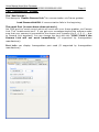


![Main lSetup l Cleanup] Parameters Locals}](http://vs1.manualzilla.com/store/data/005794368_1-f1180d1b21e5ef681561217b8f35e179-150x150.png)