1
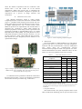
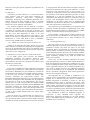
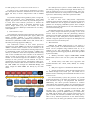
Open platform for mixed-criticality applications Miguel Méndez Macías Jose Luis Gutiérrez, David Fernández, Javier Díaz Seven Solutions Inc. Peligros, (Granada) 18210, Spain [email protected] Dpto. de Arquitectura y Tecnología de Computadores Universidad de Granada Granada, Spain {jlgutierrez, dfernandez, jdiaz}@atc.ugr.es Abstract— In this work we present a reliable and fully openhardware platform developed in the frame of RECOMP project that provides a initial approach towards the utilization of open platforms for safety critical applications. This paper describes how the platform has been developed according to the RECOMP project guidelines and taking into account the avionic standards DO-254 and DO-178C as well as the industrial standards IEC 61508. The results present a modular platform composed by two main processing chips, an ARM9 processor and a Virtex-6 FPGA with two different configurations, one based on a Quad-core Leon-3 and a Dual-core MicroBlaze. OS support based on the PikeOS and OpenRTOS-FreeRTOS respectively are provided. The paper states how open hardware platforms as here described can be used for safety-critical applications, improving the collection of evidences of robustness, reducing time-tomarket/cost and helping in the process of certification/recertifications of safety critical products. Keywords— open-hardware, reliable, COTS, safety-critical systems, certification, DO-254 standard, FPGA, multicore architecture I. INTRODUCTION Nowadays, social globalization and competitive markets are increasing the necessity of standardizing and designing highquality and reliable electronic systems. Reducing time-tomarket and costs are driving forces of this process. This is a critical factor for systems where human being integrity is at risk. In this framework, the utilization of open software elements such as RTOS, middleware and other software libraries significantly help to achieve the aforementioned goals. Unfortunately, although open hardware initiatives are becoming more and more popular, (see for instance http://www.arduino.cc/ or http://www.ohwr.org) the development of open hardware platforms for safety applications is still at a very early stage. This paper details the process and steps that we have achieved to develop a complete and reliable platform ready to be used in safety-critical systems. This platform is based in diverse and redundant powerful hardware which can provide different multi-core architectures depending on application’s necessities. Different challenges have been faced during the development of this board. To begin with, the introduction of multi-core processing platforms into these reliable systems is quite complex as it poses significant challenges on various levels like scheduling, sharing resources access or core to core communication. These problems become more critical in safety systems where a heavy validation and verification process need to be successfully accomplished. In fields like industry, automotive, automation or aeronautic, it is essential to rely on their electronic systems and use methodologies and tools, properly validated. This reason, joined to the growth and complexity of embedded systems, is the basics for the strict regulations to certify safety embedded systems. The motivation of this paper has its origin in an European project called RECOMP [1]. One of the main objectives of RECOMP project aims to reduce certification costs by developing multicore architectures for safety-critical systems where each application has its own criticality level but can coexist together on the same multicore device. In those mixedcriticality systems, the achieved criticality will not be necessarily the highest level that supplies the less reliable application provided that are used in proper isolated systems [2]. In this way, the Artemis RECOMP research project [1] seeks to form a joint European task force contributing to the European Standard Reference Technology Platform by enabling cost-efficient certification and re-certification of safety-critical systems and mixed-criticality systems based on multicore processors. The aim is to establish methods, tools and platforms to enable cost-efficient (re-)certification of safety-critical and mixed-criticality systems. The application fields addressed are: automotive, aerospace and industrial control systems as lifts or transportation systems. One of the methods to reduce certification and recertification cost, as here described, is by the utilization of an open platform. A reliable platform with different multiprocessor architectures based on reconfigurable hardware, which has been developed taking into account requirements, tools and methods that industrial and aeronautic standards apply for the safety of their systems is here described. This architecture is implemented using custom IP-cores (developed specifically for the system), COTS components, open-source hardware and commercial IP-cores to study the criticality they can achieve in addition to the advantages that they can provide to a safety-critical system. The next subsections will provide further motivation for the utilization of the open-hardware approach as well as provide a quick overview of the standard that has been considered in the development of this platform. B. Certifaction estandards The platform here presented has been developed taken into account different safety-critical requirements related to RECOMP project and its specific applications. They are: A. Open-source hardware Open-source means, with some exceptions, that the design is published for reviewing, modifying and/or producing. Most of these licenses are persistent, which means that it will remain open keeping future modifications and system improvements available to the community. Furthermore, for some licenses, manufactures must inform designers of dates and quantities of production. This process results in a more reliable design since a large number of developers and institutions are debugging, improving and using the system providing feed-back to the community. 1) IEC 61508 [4]: The Industrial standard has under its scope the electrical, electronic and programmable electronic safety systems. It is the basic functional safety standard for designers of functional-safety related devices and system integrators. This open-source methodology also allows the re-utilization of designs, making it possible to add more features to the system, or even to integrate the whole system (or some parts of it) in larger designs. But one of the main advantages that these architectures and methodology have is the reduction of costs and time-to-market of the product which is, in such a competitive market, essential. This advantage is also more effective when FPGA architectures are used because they make the design easier and more reliable as they can quickly provide a complex digital system prototype leading ultimately to a faster production of boards or applications. Certainly, there are now more advantages in using FPGAs, not only due to the fact that the number of gates and features have increased, allowing a system on- chip (SoC) to be finally realized on a single device, but also, leading FPGA vendors and open-source developers to offer easy-to-use development tools and specific IP-cores, buses, etc. that accelerate the product development and allow not only increased design productivity but also a reduction in the cost of development. Nevertheless, these embedded blocks must be configured, verified, validated and properly connected to the rest of the system in order to increase the safety and reliability of a complete system [3]. The IEC 61508 describes requirements to prevent failures by the avoidance of fault injections and to control failures by ensuring safety, even when faults are present. Additionally, the standard provides requirements for product's overall safety lifecycle. It specifies four discrete safety integrity levels (SILs)-levels of safety performance for a safety function. SIL 1 is the lowest level of safety integrity, and SIL 4 is the highest level. Requirements to achieve safety integrity at the higher levels are more meticulous than at lower levels. The SIL requirements for hardware safety integrity are based on a probabilistic analysis of the device. To achieve a concrete SIL, the dangerous failure probability must be less than the one specified, and also it must be greater than the specified safe failure fraction. These failure probabilities are calculated for instance by performing a Failure Mode and Effects Analysis (FMEA) or any of its variations. The actual targets required vary depending on the likelihood of a demand, the complexity of the device(s), and the types of redundancy used. 2) DO-254 [5] /DO-178C [6]: The aerospace safety standard is divided into different standards: DO-178B/C, Software Considerations in Airborne Systems and Equipment Certification is a document used by the US Federal Aviation Administration (FAA) to determine the conditions in which some software, that is required to be certified, is able to run, safely and reliable, in an airborne environment. Regarding the certification process, the possibility of using open-source designs allows collecting evidences of robustness and safety in the system, something hard to obtain by closed solutions. Therefore, companies that are interested in implementing and developing safety-critical systems based on open-hardware could address the certification of their system without requiring expensive qualified elements provided by third-party companies which, at the same time, do not completely solve the problem because modular certification is still (practically) not possible according to current certification standards. This software standard is normally accompanied with DO254, Design Assurance Guidance for Airborne Electronic Hardware Considerations in Airborne Systems and Equipment Certification. As main conclusion, the benefits of using an open-source hardware platform, available within the source files and documentation, can improve the collection of safety evidences that can be useful to simplify the certification process of a specific project and, as consequence, reduce the time-tomarket and associated certification cost. DO-254 standard is involved in the compliance for the design of complex electronic hardware in airborne systems. Complex electronic hardware includes devices like FPGAs, PLDs and ASICs. The hardware design and hardware verification need to be done with independence, which means that the hardware designers should work to ensure the design As SIL for the industrial field, the Design Assurance Level (DAL) is determined from the safety assessment process and hazard analysis by examining the effects of a failure condition in the system. The failure conditions are categorized by their effects on the aircraft, crew, and passengers from DAL A (highest level) to DAL E (lowest level which has no impact on safety). meets the defined requirement and the verification team should create a test that verifies all of the derived requirements. Rather than specify how to implement the standard or which test should be completed, it specifies the requirements for a process of design assurance and certification. II. BOARD SPECIFICATIONS The platform developed, which is called Avionic Computing Platform (ACP) in the framework of the RECOMP project, is a modular board composed of two boards. The core board, called AION, provides two different processor devices: an ARM9 single-processor and a Virtex-6 FPGA (where additional processors are implemented). The second board is a peripheral one, connected to AION, which includes the common peripherals to fulfil safety-critical requirements and connections requested on the RECOMP project. It is called RECOMP Sensor Board (RSB). The ACP platform connects both boards through an external interface connector, as it can be seen in the Fig. 1 where AION, RSB and ACP are shown. Both boards have been designed by Seven Solutions as an open-hardware design. Figure 2: Avionic Computing Platform Diagram A. AION board The board includes an ARM (SAM9G45 [7]) and a FPGA (Virtex-6 [8]) device, as processors, and some peripherals, memories and fast external/interface connectors (differential pair), which allow the communication between external/extension/peripheral boards. The physical size of the AION board fulfils the microTCA standard in order to be also used as a co-processor platform in microTCA systems. TABLE I. AION+RSB PERIPHERAL DETAILS AION peripherals Processor connections FPGA External memory X X External WatchDog X X c X Ethernet Port X USB port (OHCI host port and transceiver) Figure 1: Images of the development platform. AION on the top-left, RSB on the top-right and finally ACP on the bottom of the picture are the board shown in the picture. To understand all the possibilities and FPGA architectures that this board provides, a review of its hardware components and structure has been provided on Fig. 2 and Table 1. ARM a a Share Xb X Serial ports (RS232, SPI) Xc X LEDs and buttons Xc X JTAG debug and configuration port X X Temp. sensors and FPGA onchip monitor (voltage supply and temp.) X General Purpuse I/O X X VCO with PLLx5 and oscillators X X X X a. The ARM has 64MB of DDR2 and 512MB of Flash, while the FPGA has 4.608 MB of QDRII RAM and 32MByte of Flash. b. Through a FPGA controller. It controls the communication between ARM and FPGA which is done through a 32 bits asynchronous bus that can be customized. c. Through the RSB board. This board includes a few general peripherals and it would rather include serial and debug ports for processor devices and memories, leaving the specific application peripherals for the RSB board. B. RSB board The RSB, as its name indicates, is a sensor board where some actuators, serial ports and others peripherals are implemented following safety-critical requirements. Furthermore, monitoring ports, redundant peripherals and a monitor display have been included in order to facilitate testing, to increase the safety capabilities and to be able to monitor the correct operation of the platform. The common peripherals like two Ethernet, two RS232 serial port, eight LEDs (with a feedback mechanism so that it is possible to read their state at the end of the line), five position LEDs and five buttons are implemented in this board and they have been duplicated in order to be used independently for each AION processor (see Table 1). This allows on one hand, to implement an AMP multiprocessor architecture, or, in the other hand, to have a redundancy system in case of SMP multicore architecture. III. FPGA MULTICORE PROCESSOR ARCHITECTURES Thanks to the flexibility that Xilinx FPGAs [9] provide, different multi-core architectures depending on the application needs can be implemented. In this paper, two different multicore architectures are presented. They are based on COTS and open-source IP core components. A. AMP dual-processor architecture based on Microblaze In an AMP system, each processor has different independent peripherals and memories. Moreover, each software process and OS is locked to a single core, which means that they only share one communication channel, a fast and safe bus, to share data. 1) FGPA hardware layer In this case, a full FPGA on-chip architecture is developed using the tools provided by the vendor (ISE suite from Xilinx) and tested by ModelSim [10] and ChipScope. It fulfils the communication and control of each board peripheral whereas, at the same time, provides a suitable and reliable dualprocessor architecture for safety-critical systems. Two independent Microblaze softprocessor [11] are implemented in the FPGA, meaning that each Microblaze has all peripherals and memories it needs to run independently. This can be possible since the ACP board provides two different QDRII memory chips connected to the FPGA and the RSB duplicated peripherals, following the chosen AMP architecture. Both processors are connected to each other through mailbox and mutex IP-cores in order to share data packets and instructions; as well as with a 64KB shared memory for sharing larger amount of data. Since the project uses a Xilinx FPGA, the fastest way to develop an on-chip architecture is to use the controllers and cores provided by Xilinx, which have been already tested and validated. Given that, the Microblaze processors are connected to the peripherals and external memories through a PLB bus which will be the main bus of the system. Moreover, a variety of IP-cores, tools and their history of use can help to go through the certification process since homologous IP-cores (the commonly used) and the Microblaze processor are being implemented in a safe and certifiable way for Xilinx in collaboration with third-party partners in the frame of critical projects. This development process does not ensure the certification of the entire system since no modular/partial certification is possible but the history of its utilization makes easier the recertification in future projects. This architecture gives functionality to all peripherals and memories included in hardware, implementing some safety mechanisms like dual and diverse channels for each QDRII memory, and isolation between external peripherals. It also includes a bridge between a PLB proprietary bus and an open-source bus (Wishbone) in each processor so that any open-source controller can be safely included in the architecture. 2) OS and application layer The main target of the current architecture focuses on industrial applications. We have developed simple routines to periodically monitor and check the status of the board peripherals. Hence, the utilization of a Real-Time Operating System (RTOS) is mandatory because it provides the system with multitasking features. Moreover, the possibility of adding a priority level to any single task, is obligatory for achieving a proper scheduling, specially a key point for reliable and safety-critical systems. In this case, we have decided to implement our system using FreeRTOS [12], which is a market leading RTOS from Real Time Engineers Ltd. Furthermore, FreeRTOS is an opensource OS making the whole system strictly quality controlled, robust, supported, and free to use in commercial products. It is also worth to mention that there are additional compatible versions of FreeRTOS, such as OpenRTOS and SafeRTOS that are specifically designed for safety-critical applications but they are not used in this design. The application test we provided is composed by two running versions of FreeRTOS. Each FreeRTOS program is mapped into a different processor, which is connected to different peripherals as described in section II. The first FreeRTOS instance, which is mapped to processor0, owns tasks related to: temperature sensors, serial port outputs, board LEDs, buttons, and LCD status messages. On the other hand, the other FreeRTOS instance is mapped to processor1 and is in charge of performing system monitoring measurements and controlling DIP switch changes, LEDs and serial port outputs. The combination of these two FreeRTOS programs, in conjunction to their scheduled tasks, represents the demonstrator application developed for the ACP platform using a MicroBlaze-targeted architecture, which has been described on previous sections. B. SMP quad-processor architecture based on Leon-3 In order to cover a wider range of architectures, we have also developed an alternative architecture for the ACP board, based, this time, on Leon-3 softprocessors with an AMBA bus. In symmetric multiprocessing (SMP) systems, a single OS, manages all processor cores simultaneously. With SMP support, any processor can execute any task allowing the OS to easily move tasks between processors to balance the workload efficiently, which is something important in the current design needs [13]. For this reason, we found interesting to design a SMP open architecture for our safetycritical platform. 1) FPGA hardware layer The architecture is based on the well-known soft-processor Leon3, developed by the European Space Agency (ESA) and Gaisler Aeroflex. LEON3 is a 32-bit processor core conforming to the [IEEE-1754] (SPARC V8) architecture. It is described in synthesizable VHDL with a GPL license and it has multi-processing support for SMP [14]. The architecture consists of four Leon3 processors connected to a single AMBA bus. This bus is arbitrated by the AMBA controller which connects all the elements in the system in a master-slave configuration, allowing all processors to communicate which each other through a QDRII slave memory. In addition to these main components, the following ones are also included: the timer controller is the element in charge of each of the timers for each processor. The IRQ element is accessible through the bus AMBA to trigger an interrupt on each processor. Several elements are used to communicate the board with the surroundings: GPIO ports, Ethernet ports and the UART. Some of them are accessible in the APB AMBA bus through the AHB-APB Bridge, and others trough the AHB AMBA bus directly by the main arbiter. The multi-processor system is used in SMP mode, using the message passing mechanism through shared memory in order to perform the core-to-core communications. Also, nonshared cache memories for each processor are added to speedup access to main memory and reduce system bus traffic. 2) OS application layer In order to meet some safety-critical requirements regarding spatial and time isolation (see section IV) the ACP Leon3 architecture uses the hypervisor PikeOS. PikeOS is a platform for developing embedded systems where multiple operating systems and applications can run simultaneously in a secure environment [15]. The PikeOS architecture is based on a microkernel design with a small, compact microkernel providing a core set of services such as resource and time partitioning. Resource partitions provide spatial segregation between applications in a way that write at the same place in shared memory is not allowed. Using time partitions we improve the management of concurrent access to the memory bus. C. ARM utilization Although the ARM9 single-processor is not used as a safety critical system, it has been flashed with a vanilla linux kernel v2.6.39 (compiled using buildroot 2011.11) as an example of use. This development is open-source design which supports the following peripherals (all of them provided by the ACP board): Memory controllers’ support: 64MB DDR2, 256MB NAND Flash (used as the root file system) and 8MB boot flash. TCP/IP library and SSH server supported with standard daemons like: TFTP, DNS, DHCP, etc already includes. EBI port’s support to communicate with the FPGA. Specific application to flash the FPGA directly from the ARM through serial JTAG port. The ARM can be therefore used as watchdog and reinitialized the FPGA in case an error occurs. In a mixed-criticality system, this processor can provide monitoring functions to the safety part whereas it is isolated from the FPGA using its own peripherals and memories. Additionally, this device provides robustness to common cause effects that could affect FPGA cores and therefore help to increase the certification capabilities of the whole platform. Figure 3 Quad-core Leon3 architecture In order to enable communication between the safe and non-safe part, a specific controller is developed. This controller shares part of the QDRII memory to connect both, the ARM and the FPGA. Since isolation between these two parts is needed, the controller (included in the safety part) is able to set by hardware permission for the shared memory part. In this case, the safety part (FPGA) is able to read and write to the whole shared memory, while the non-safety part (ARM) is just able to read data. IV. SAFETY MECHANISMS A typical approach to achieve safety in complex systems consists in proving that the relation between different subsystems is deterministic and known, or even non-existent. For this reason, spatial and time partitioning are common practices. In this section we show how we ensure time and spatial isolation, as well as memory protection and secure core-to-core communications in our different architectures. A. Isolation The platform gives the possibility to have an AMP multicore architecture thanks to the separated memory chips, external WatchDogs, different clock oscillators and duplicated peripherals which provide isolation between cores. Moreover, the ACP has two different processor devices that can provide diversity: ARM single-processor and a FPGA multiprocessor architecture with possible safety mechanisms. In the SMP architecture everything is shared. Then, isolation is achieved, basically, through memory and bus contention, cache coherency, and concurrent and exclusive access mechanism performed by the OS. Concurrent access to shared memory and bus is avoided at hardware level by the bus arbiter and the bus architecture itself. Although it can be said that there is only one shared bus, in fact there are multiple sub-buses that connect each component to the bus arbiter in a star topology. The bus arbiter acts as a multiplexer, provides a time division multiple access contention (TDMA) against concurrent access, where the priority is rotated among all masters requesting the bus each AHB transfer where the worst-case-execution-time to access the bus is bounded up. B. C2C communication Different mechanisms for commutation can be used in this system. The FPGA multiprocessor architecture can use two mechanisms: Xilinx cores: mutex and mailbox, for free communication matters between buses. These cores provide simple synchronization and message passing features between the two processors. Wittenstein (http://www.highintegritysystems.com/) libraries over the OpenRTOS which provides safety and reliable communication between cores. Whereas the ARM single-processor is connected to the FPGA architecture through an EBI bus, meaning that a shared memory (within the QDRII external memory) is used as a core-to-core communication between ARM-FPGA architectures. The C2C controller is implemented in a way that both cores are isolated and one can not affect the memory access of the other. C. System memory protection At hardware level, diversity within memory chips can handle some hardware failure as well as isolation between processors. Moreover, the QDRII controller is initialized with a calibration process that evaluates the correct behaviour of the memory. It also has the possibility to include a parity bit protection mechanism for each memory byte. In order also to avoid bus failures the QDRII controller has two independent channels with different bus access implemented (PLB [16] and Wishbone [17] bus). In the SMP architecture, where the main memory is totally shared, coherency mechanisms are also needed. The use of the write-through caches for each processor, along with the snooping mechanism, guarantee memory coherency in main shared memory [18]. D. Operating system In this kind of systems, it is common to use a Memory Management Unit (MMU) to handle CPU memory access requests. Unfortunately, MMU support is not available in FreeRTOS for MicroBlaze architectures. However, this RTOS provides other mechanisms to fill this lack which is the utilization of a scheduler and the possibility of running tasks atomically. Owing to guarantee the correct behaviour of the AMP platform and the schedulability of the tasks that are executed in each processor, FreeRTOS offers a routine that ensures the atomic execution of critical sections. These routines are: portENTER_CRITICAL(); portEXIT_CRITICAL(); The utilization of these routines ensures that the instructions which are in between, are executed atomically. This means that the scheduler will never extract the task from the processor during the execution of these lines, avoiding undesirable and unpredictable reads/writes on peripherals. Example: TABLE II. CRITICAL SECTION SOURCE CODE portENTER_CRITICAL(); { QDRIImemory_test(XPAR_WBANDPLB_QDRII_0_BASEA DDR, XPAR_PLB2WB_BRIDGE_0_BASEADDR); } portEXIT_CRITICAL(); As described in the figure above, the QDRIImemory_test() function involves several clock cycles to test all the memory. Since this test performs writing and reading data from the memory, the fact of stopping and resuming the task that arranges this test, can bring to an inconsistent state of the memory, ignoring any undesirable behaviour and erroneous readings. By adding the routines portENTER_CRITICAL() and portEXIT_CRITICAL(), we ensure that the test is accomplished atomically, ensuring the correct reading and writing process in, for example, shared devices. Other safety mechanism available for RTOS is the virtualization of different shared resources. This feature is not available for FreeRTOS but it is for PikeOS, as discussed in the previous section, which achieves time and spatial isolation by using a hypervisor with resource and time partitions support. [19] The purpose of the resource partitions is to provide spatial segregation between applications (using the underlying hardware memory protection capabilities) and to control access to system resources such as IO devices and memory. Time partitioning is a mechanism for allocating CPU time amongst the partitions. It can be used to ensure that all partitions get a predefined amount of execution time and to prevent any thread from starving others, even in the case of a faulting thread. In its simplest form, time partitioning can be used to allocate a certain CPU quota to each resource partition. E. Test and verification For hardware fabrication: Acceptance of finished printed boards is in accordance with IPC-A-600, class 2. Fabrication and inspection are according to IPC-6011 and IPC-6012, class 3. And all quality controls are performed per IPC-TM-650 procedures and per IPC-4552. On the other hand, depending on the FPGA architecture, different test and verification methods and tools are used. For instance, the Microblaze architecture simulation tests have been done with ModelSim from Mentor Graphics [19], and the hardware analysis with ChipScope from Xilinx. These tests provide verification at functional level for those specific IPcores created for the design and for the complete system. redundant diverse field equipment can help unmask additional dangerous undetected faults, thus increasing Safe Failure Fraction. On the other hand, the paper also describes how the system cost and time-to-market can be reduced by the opensource philosophy or the possibility to use COTS components. Finally, this paper introduces the open-hardware/opensource approach inside the certification process as open-boxes or systems. As important advantage, it helps to save time-tomarket and development costs but, as key element, the utilization of open platforms helps to improve the reliability of the overall system because reviewers, source code and documented safety evidences can be completely examined and verified. As consequence, the main goal of safety-critical systems, reducing the risk of damage of human beings, can be better guarantied. REFERENCES [1] [2] [3] [4] [5] [6] [7] [8] Nevertheless, a more exhaustive validation and verification method for each IP-core and the overall system should be provided to pass the certification process of safety-critical system V. [9] [10] CONCLUSIONS We have presented a reliable open hardware platform based on the requirements of RECOMP project and industrialavionics safety standards. It introduces safety hardware mechanisms like environmental monitoring, redundant and diverse peripherals as well as different multicore architectures using the FPGA: a Quad-core Leon-3 and a Dual-core MicroBlaze. OS support based on the PikeOS and OpenRTOS-FreeRTOS respectively are provided for each configuration, adding safety options to the overall system. On the other hand, the ARM9 flashed with a standard Linux OS provides a simple interface for non-safety part or low critical applications, whereas an isolated multicore-processor is on the FPGA. [11] This paper describes a feature-rich platform with many applications on safety related industrial and aerospace markets, and briefly describes how system’s reliability can be increased by diverse redundancy. As has been previously said, [18] [12] [13] [14] [15] [16] [17] RECOMP Project website, Accessed on Nov. 2012 at: http://www.recomp-project.eu/ Anton Hattendorf, Andreas Raabe and Alois Knoll. Shared Memory Protection for Spatial Separation in Multicore Architectures. In 7th IEEE International Symposium on Industrial Embedded Systems (SIES'12). Karlsruhe, Germany, 2012. Bsiss Mohammed and Amami Benaissa. Safety Fuzzy Logic Controller of 1oo2 Architecture for FPGA Implementation. April 20, 2011 IEC 61508: IEC Standard 61508, March 2000. Functional Safety of Electrical / Electronic /Programmable Electronic Safety-Related Systems RTCA DO-254/EUROCAE ED-80 “Design assurance guidance for airborne electronic hardware,” RTCA, Inc, Tech. Rep., 19th April 2000. RTCA DO-178 “Software considerations in airborne systems and equipment certification,” RTCA, Inc, Tech. Rep., 1st Dec. 1992. Last version DO-178C release in Jan. 2012. AT91SAM ARM-based Embedded MPU SAM9G45. Accessed on Sep. 2012: http://www.atmel.com/Images/doc6438.pdf Virtex-6 Family overview delivered 28.Jan.2010. Accessed on Sep. 2012: http://www.xilinx.com/support/documentation/data_sheets/ds150.pdf Xilinx website. Accessed on Sep. 2012: http://www.xilinx.com/ ModelSim User’s Manual (software version 6.4a). Accessed on Sep. 2012: http://hornad.fei.tuke.sk/predmety/ncs/FPGA_Advantage_Documentatio n/modelsim_se_user.pdf Microblaze Processor Reference Guide. Accessed Sep. 2012: http://www.xilinx.com/support/documentation/sw_manuals/xilinx13_1/ mb_ref_guide.pdf FreeRTOS Real-Time Operating System. Accessed on Nov. 27, 2012. http://www.freertos.org/ SMP - Simetric Multiprocessing. GRLIB IP Library User’s Manual, Aeroflex Gaisler, 2012. PikeOS 3.3 Datasheet http://www.sysgo.com/nc/products/documentcenter/data-sheets/?cid=1431&did=797&sechash=204a3eca PLBv4.6 Slave Burst (v1.01a) Product Specifications. DS562 June 22, 2010. Accessed on Spe. 2012: http://www.xilinx.com/support/documentation/ip_documentation/plbv46 _slave_burst.pdf Wishbone B4 specifications. Accessed on Sep. 2012: http://cdn.opencores.org/downloads/wbspec_b4.pdf GRLIB IP Core User’s Manual, Aeroflex Gaisler, 2012. Mentor Graphic. Accessed on Sep. 13: http://www.mentor.com/