1
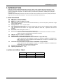
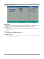
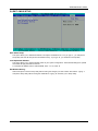
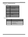
AR-B1898 User’s Guide AR-B1898 INDUSTRIAL GRADE NETWORKING COMPUTER User’ s Guide Edition: 1.0 Book Number: AR-B1898-07.0307 1 AR-B1898 User’s Guide Table of Contents 0. PREFACE.................................................................................................................................................................... 3 0.1 COPYRIGHT NOTICE AND DISCLAIMER .....................................................................................................................................3 0.2 WELCOME TO THE AR-B1898 CPU BOARD................................................................................................................................3 0.3 BEFORE YOU USE THIS GUIDE ...................................................................................................................................................3 0.4 RETURNING YOUR BOARD FOR SERVICE.................................................................................................................................3 0.5 TECHNICAL SUPPORT AND USER COMMENTS ........................................................................................................................3 0.6 STATIC ELECTRICITY PRECAUTIONS ........................................................................................................................................4 1. INTRODUCTION.......................................................................................................................................................... 5 1.1 SPECIFICATIONS ..........................................................................................................................................................................5 1.2 AR-B1898’S SERIAL TABLE ..........................................................................................................................................................5 1.3 PACKING LIST................................................................................................................................................................................6 2. INSTALLATION........................................................................................................................................................... 7 2.1 AR-B1898'S LAYOUT .....................................................................................................................................................................7 3. CONNECTION ............................................................................................................................................................. 8 3.1 ATX POWER CONNECTOR FOR ATX POWER SUPPLY ............................................................................................................8 3.2 AT POWER CONNECTOR FOR AT ADAPTER (PWR1) ...............................................................................................................8 3.3 CLEAR CMOS (JBAT1)...................................................................................................................................................................8 3.4 SATA POWER CONNECTOR( ) .....................................................................................................................................................8 3.5 ULTRA ATA33/66/100 IDE DISK DRIVE CONNECTOR (IDE1, IDE2) ..........................................................................................9 3.6 COMPACT FLASH CARD (J1)........................................................................................................................................................9 3.7 SERIAL PORTS (COM1, COM2)....................................................................................................................................................9 3.8 KEYBOARD / MOUSE CONNECTOR (KBMS1).............................................................................................................................9 3.9 INTERNAL USB PIN HEADER (USB2~USB4) .............................................................................................................................10 3.10 EXTERNAL USB TYPE-A CONNECTOR (USB1) ......................................................................................................................10 3.11 FAN CONNECTOR (FAN1,FAN2) ..............................................................................................................................................10 3.12 ETHERNET RJ45 CONNECTOR (LAN1~LAN4) ........................................................................................................................10 3.13 ETHERNET LED (LED1~LED4)..................................................................................................................................................10 3.14 LAN1& LAN2 BYPASS FUNCTION SLECTION(J4) ...................................................................................................................10 3.15 VGA CRT CONNECTOR (VGA1) ...............................................................................................................................................10 3.16 GENERAL PURPOSE I/O (GPIO1).............................................................................................................................................11 3.17 POWER BUTTON & RESET BUTTON .......................................................................................................................................11 3.18 POWER/RESET/PWR LED/HDD LED PIN HEADER (J2) .........................................................................................................11 3.19 POWER/HDD/BYPASS LED(LED5) ...........................................................................................................................................11 4. WATCHDOG & GPIO ................................................................................................................................................ 12 4.1 WATCHDOG TIMER SETTING ....................................................................................................................................................12 4.2 GPIO SETTING .............................................................................................................................................................................12 5. BIOS CONSOLE........................................................................................................................................................ 13 5.1 BIOS SETUP NOTICE ..................................................................................................................................................................13 5.2 MAIN CMOS SETUP.....................................................................................................................................................................14 5.3 ADVANCED CMOS SETUP..........................................................................................................................................................15 5.4 POWER SETUP ............................................................................................................................................................................16 5.5 PNP/PCI CMOS SETUP ...............................................................................................................................................................17 5.6 PERIPHERALS CMOS SETUP.....................................................................................................................................................18 5.7 PC HEALTH CMOS SETUP..........................................................................................................................................................20 5.8 BOOT CMOS SETUP....................................................................................................................................................................21 5.9 EXIT CMOS SETUP......................................................................................................................................................................22 5.10 BIOS UPDATE ............................................................................................................................................................................23 APPENDIX A. ADDRESS MAPPING ............................................................................................................................ 24 APPENDIX B. INTERRUPT REQUEST (IRQ)............................................................................................................... 25 2 AR-B1898 User’s Guide 0. PREFACE 0.1 COPYRIGHT NOTICE AND DISCLAIMER This document is copyrighted, 2005, by Acrosser Technology Co., Ltd. All rights are reserved. No part of this manual may be reproduced, copied, transcribed, stored in a retrieval system, or translated into any language or computer language in any form or by any means, such as electronic, mechanical, magnetic, optical, chemical, manual or other means without the prior written permission or original manufacturer. Acrosser Technology assumes no responsibility or warranty with respect to the content in this manual and specifically disclaims any implied warranty of merchantability or fitness for any particular purpose. Furthermore, Acrosser Technology reserves the right to make improvements to the products described in this manual at any times without notice. Such revisions will be posted on the Internet (WWW.ACROSSER.COM) as soon as possible. Possession, use, or copy of the software described in this publication is authorized only pursuant to valid written license from Acrosser or an authorized sub licensor. ACKNOWLEDGEMENTS Acrosser, AMI, IBM PC/AT, Windows, MS-DOS…are registered trademarks. All other trademarks and registered trademarks are the property of their respective owners. 0.2 WELCOME TO THE AR-B1898 CPU BOARD This guide introduces the Acrosser AR-B1898 CPU Board. Use information provided in this manual describes this card’s functions and features. It also helps you start, set up and operate your AR-B1898. General system information can also be found in this publication. 0.3 BEFORE YOU USE THIS GUIDE Please refer to the Chapter 1, “Introduction” in this guide, if you have not already installed this AR-B1898. Check the packing list before you install and make sure the accessories are completely included. AR-B1898 CD provides the newest information regarding the CPU card. Please refer to the files of the enclosed utility CD. It contains the modification and hardware & software information, and adding the description or modification of product function after manual printed. 0.4 RETURNING YOUR BOARD FOR SERVICE If your board requires any services, contact the distributor or sales representative from whom you purchased the product for service information. If you need to ship your board to us for service, be sure it is packed in a protective carton. We recommend that you keep the original shipping container for this purpose. You can help assure efficient servicing for your product by following these guidelines: 1. Include your name, address, daytime telephone, facsimile number and E-mail. 2. A description of the system configuration and/or software at the time of malfunction. 3. A brief description of the problem occurred. 0.5 TECHNICAL SUPPORT AND USER COMMENTS Users comments are always welcome as they assist us in improving the quality of our products and the readability of our publications. They create a very important part of the input used for product enhancement and revision. We may use and distribute any of the information you provide in any way appropriate without incurring any obligation. You may, of course, continue to use the information you provide. If you have any suggestions for improving particular sections or if you find any errors on it, please send your comments to Acrosser Technology Co., Ltd. or your local sales representative and indicate the manual title and book number. Internet electronic mailto:[email protected] [email protected] 3 AR-B1898 User’s Guide 0.6 STATIC ELECTRICITY PRECAUTIONS Before removing the board from its anti-static bag, read this section about static electricity precautions. Static electricity is a constant danger to computer systems. The charge that can build up in your body may be more than sufficient to damage integrated circuits on any PC board. It is, therefore, important to observe basic precautions whenever you use or handle computer components. Although areas with humid climates are much less prone to static build-up, it is always best to safeguard against accidents that may result in expensive repairs. The following measures should be sufficient to protect your equipment from static discharge: Touch a grounded metal object to discharge the static electricity in your body (or ideally, wear a grounded wrist strap). When unpacking and handling the board or other system components, place all materials on an anti-static surface. Be careful not to touch the components on the board, especially the “golden finger” connectors on the bottom of the board. 4 AR-B1898 User’s Guide 1. INTRODUCTION Welcome to the AR-B1898 serial Networking Computer, which comes equipped with high performance VIA ® NanoBGA2 Processor with the VIA ® advanced chipset (CN700 and VT8251). This product is designed for the system manufacturers, integrators, or VARs that want to provide all the performance, reliability, and quality at a reasonable price. In addition, the AR-B1898 provides on chip VGA. The VGA, which provides up to True Color (32 bit) 1024x768, or High Color (16 bit) 1280x1024 resolution. The VGA memory shared with main memory. 1.1 SPECIFICATIONS CPU: VIA ® C7 1GHz NanoBGA2. Chipset: VIA ® CN700 and VT8251 Memory: 2 x DDR2 SO-DIMM, up to 2GB VGA Controller: Embedded VGA controller, Screen Resolution: up to True Color (32 bit) 1024x768, or High Color (16 bit) 1280x1024. Display Interface: CRT – 2x5 pin header. Ultra ATA/33/66/100 IDE Interface: Two PCI Enhance IDE channel. The south bridge VT8251 supports Ultra ATA/33/66/100 IDE interface. To support Ultra ATA66/100 Hard disk, a specified cable must be available. Serial ATA: Serial ATA Singal connector x4 Series ports: Two high-speed 16550 compatible UARTs ports. COM1: On-board D-SUB 9-pin male external port and 2x5x2.54mm Pin-Header connector. COM2: On-board one 2x5x2.54mm Pin-Header connector USB port: Support six USB 2.0 compatible ports. Watchdog timer: Software programmable 1~63sec. Two PCI interface Embedded LAN (Broadcom 10/100M 4401 or Giga LAN 5788): 2 ports IEEE 802.3u Auto-Negotiation support for 10BASE-T/100BASE-TX/1000BASE-TX. Built-In Watch-Dog Timer for Bypass function between port 1 and port 2. Connected to your LAN through RJ45 connector. Two PCI-E interface Embedded LAN (Broadcom 10/100M 5906 or Giga LAN 5787: 2 ports IEEE 802.3u Auto-Negotiation support for 10BASE-T/100BASE-TX/1000BASE-TX. Connected to your LAN through RJ45 connector. Keyboard Connector & PS/2 Mouse: JST 6 Pin Header Operating Temperature: 0° ~ 60℃. 1.2 AR-B1898’S SERIAL TABLE AR-B1898 AR-B1898A AR-B1898B PCI Broadcom5788 Broadcom4401 Broadcom4401 PCI-E Broadcom5787 Broadcom5787 Broadcom5906 5 AR-B1898 User’s Guide 1.3 PACKING LIST In addition to this User's Manual, the AR-B1898 package includes the following items: The quick setup manual 1 AR-B1898 CPU board 1 Hard disk drive adapter cable (40Pin) (optional) 1 Hard disk drive adapter cable (44Pin) (optional) 1 Software utility CD 1 PS/2 Mouse & Keyboard interface Y-cable 1 SATA signal cable 1 VGA cable 6 AR-B1898 User’s Guide 2. INSTALLATION This chapter describes how to install the AR-B1898. At first, the layout of AR-B1898 is shown, and the unpacking information that you should be careful is described. The following lists the jumpers and switches setting for the AR-B1898’s configuration. 2.1 AR-B1898'S LAYOUT 7 AR-B1898 User’s Guide 3. CONNECTION This chapter describes how to connect peripherals, switches and indicators to the AR-B1898 board. 3.1 ATX POWER CONNECTOR FOR ATX POWER SUPPLY 3.1.1 (CON6) PIN 1 2 3 Signal GND ATX PSON 5VSB 3.1.2 (PWR2) PIN 1 2 Signal +12V GND 3.2 AT POWER CONNECTOR FOR AT ADAPTER (PWR1) Pin 1 2 3 4 Signal GND GND +12V +12V 3.3 CLEAR CMOS (JBAT1) If want to clear the CMOS Setup (for example when you forgot the password, please clear the setup and then set the password again.), you should close the pin 2-3 about 3 seconds, then open again, set back to normal operation mode, close the pin 1-2. 1 JP4 1-2 ON 3 2-3 ON FUNCTION Normal Operation (Factory Preset) Clear CMOS 3.4 SATA POWER CONNECTOR( ) J4 1 2 3 4 FUNCTION +12V GND +3.3V +5V 8 AR-B1898 User’s Guide 3.5 ULTRA ATA33/66/100 IDE DISK DRIVE CONNECTOR (IDE1, IDE2) • IDE1: Primary IDE Channel (IDE1) A 40-pin header type connector (IDE1) is provided to interface with up to two embedded hard disk drives (IDE AT bus). This interface, through a 40-pin cable, allows the user to connect up to two drives in a “daisy chain” fashion. To enable or disable the hard disk controller, please use the BIOS Setup program, which is explained further in chapter 5. The following table illustrates the pin assignments of the hard disk drive’s 40-pin connector. 2 40 1 39 • IDE 2: Second IDE Channel (IDE2,CF1) AR-B1898 provides IDE interface 44-pin connector to connect with the hard disk device. 2 44 1 43 3.6 COMPACT FLASH CARD (J1) PIN Short Open Signal CF MASTER CF SLAVE (Factory default) 3.7 SERIAL PORTS (COM1, COM2) COM1 D-SUB 9-PIN COM2 2x5 pin header PIN 1 3 5 7 9 Signal /DCD RX TX /DTR GND PIN 2 4 6 8 10 Signal /DSR /RTS /CTS /RI N.C. 3.8 KEYBOARD / MOUSE CONNECTOR (KBMS1) • PS2: JST6-pin Keyboard/Mouse Connector PIN 1 2 3 4 5 6 Signal MSDATA KBDATA GND VCC MSCLK KBCLK 9 AR-B1898 User’s Guide 3.9 INTERNAL USB PIN HEADER (USB2~USB4) PIN 1 3 5 7 Signal VCC USBDUSBD+ GND PIN 2 4 6 8 Signal GND USBD+ USBDVCC PIN 5 6 7 8 Signal VCC USBDUSBD+ GND 3.10 EXTERNAL USB TYPE-A CONNECTOR (USB1) PIN 1 2 3 4 Signal VCC USBDUSBD+ GND 3.11 FAN CONNECTOR (FAN1,FAN2) PIN 1 2 3 Signal GND +12V SENSE 3.12 ETHERNET RJ45 CONNECTOR (LAN1~LAN4) The Ethernet RJ-45 connectors are the standard network headers. The following table is the pin assignment. : Link LED : Act LED Pin 1 2 3 4 Signal TX+ TXRX+ Not Used Pin 5 6 7 8 Signal Not Used RXNot Used Not Used 3.13 ETHERNET LED (LED1~LED4) LED Green Green Yellow FUNCTION 1000Mbps 100Mbps Action 3.14 LAN1& LAN2 BYPASS FUNCTION SLECTION(J4) PIN 1-2 2-3 FUNCTION LAN1&LAN2 Bypass State LAN1&LAN2 Normal State 3.15 VGA CRT CONNECTOR (VGA1) PIN 1 3 5 7 9 Signal RED GREEN BLUE VSYNC HSYNC PIN 6 4 6 8 10 Signal GND GND GND SCLK SDATA 10 AR-B1898 User’s Guide 3.16 GENERAL PURPOSE I/O (GPIO1) Pin 1 3 5 7 9 Signal GPIO0 GPIO1 GPIO2 GPIO3 GND Pin 2 4 6 8 10 Signal +5V GPIO4 GPIO5 GPIO6 GPIO7 3.17 POWER BUTTON & RESET BUTTON 3.18 POWER/RESET/PWR LED/HDD LED PIN HEADER (J2) Pin 2-4 3-5 6-8 10-12 INDICATION HDD LED (2+) PWR LED(3+) POWER BTN RESET BTN 3.19 POWER/HDD/BYPASS LED(LED5) LED Green Green Yellow FUNCTION Power ON Hard Disk Active Watch Dog Bypass timeout 11 AR-B1898 User’s Guide 4. WATCHDOG & GPIO 4.1 WATCHDOG TIMER SETTING The Watchdog Timer is provided to ensure that standalone systems can always recover from catastrophic conditions that cause the CPU to crash. This condition may have occurred by external EMI or a software bug. When the CPU stops working correctly, hardware on the board will either perform a hardware reset (cold boot) or a Non-Maskable Interrupt (NMI) to bring the system back to a known state. 1. 2. 3. Watch Dog Timer is controlled by CRF3, CRF4, CRF6, CRF7 of Logical Device 8 of Super I/O (W83697HG) Timer range 1-255 second / minute To test the Watch Dog function, we have developed a program and it run under DOS OS. 4.2 GPIO SETTING The GPIO are controlled by Register of Super I/O IC (W83697HF). For details please refer the datasheet of W83697HF. GPIO can be only set as all inputs or all outputs. To test GPIO of AR-B1898, we have developed Test program “GPIO.EXE” and run under DOS Operating system. 12 AR-B1898 User’s Guide 5. BIOS CONSOLE This chapter describes the AR-B1898 BIOS menu displays and explains how to perform common tasks needed to get up and running, and presents detailed explanations of the elements found in each of the BIOS menus. The following topics are covered: z z z z z z z z Main Advanced Power PnP/PCI Peripherals PC Health Boot Exit 5.1 BIOS SETUP NOTICE The BIOS is a program used to initialize and set up the I/O system of the computer, which includes the ISA bus and connected devices such as the video display, diskette drive, and the keyboard. The BIOS provides a menu-based interface to the console subsystem. The console subsystem contains special software, called firmware that interacts directly with the hardware components and facilitates interaction between the system hardware and the operating system. The BIOS default values ensure that the system will function at its normal capability. In the worst situation the user may have corrupted the original settings set by the manufacturer. After the computer is turned on, the BIOS will perform diagnostics on the system and display the size of the memory that is being tested. Press the [Del] key to enter the BIOS Setup program, and then the main menu will show on the screen. The BIOS Setup main menu includes some options. Use the [Up/Down] arrow key to highlight the option that you wish to modify, and then press the [Enter] key to select the option and configure the functions. CAUTION: 1. AR-B1898 BIOS the factory-default setting is used to the <Optimized Defaults> Acrosser recommends using the BIOS default setting, unless you are very familiar with the setting function, or you can contact the technical support engineer. 2. If the BIOS settings are lost, the system will detect the <COMS checksum error> and boot the operation system, that situation will reduce the performance of the system. Acrosser recommends you to reset the <Optimized Defaults>. This option gives best-case values that should optimize system performance. 3. The BIOS settings are described in detail in this section. 13 AR-B1898 User’s Guide 5.2 MAIN CMOS SETUP The <Main CMOS Setup> option allows you to record some basic system hardware configuration and set the system clock and error handling. If the CPU board is already installed in a working system, you will not need to select this option anymore. Main CMOS Setup Date The date format is: Day: Sun to Sat Month: JAN to DEC Date: 1 to 31 Year: 1999 to 2099 To set the date, highlight the Date field and use the PageUp / PageDown or +/- keys to set the current time. Time The time format is: Hour: 00 to 23 Minute: 00 to 59 Second: 00 to 59 To set the time, highlight the Time field and use the PageUp / PageDown or +/- keys to set the current time. IDE Setup The IDE adapters control the hard disk drive.Use a separate sub menu to configure each hard disk drive IDE HDD Auto-detection Press Enter to auto-detect the HDD on this channel. If detection is successful, it fills the remaining fields on this menu. IDE Primary Master None Auto Manual Capacity Auto Display your disk drive size. Disk drive capacity (Approximated). Note that this size is usually slightly greater than the size of a formatted disk given by a disk checking program. Access Mode Choose the access mode for this hard disk Halt On This field determines whether the system will halt if an error is detected during power up. No errors The system boot will not be halted for any error that may be detected. (Default) All errors Whenever the BIOS detect a non-fatal error, the system will stop and you will be prompted. All, But Keyboard The system boot will not be halted for a keyboard error; it will stop for all other errors All, But Diskette The system boot will not be halted for a disk error; it will stop for all other errors. All, But Disk/Key The system boot will not be halted for a key- board or disk error; it will stop for all others. 14 AR-B1898 User’s Guide 5.3 ADVANCED CMOS SETUP Advanced CMOS Setup Quick Power On Self Test When enabled, this field speeds up the Power On Self Test (POST) after the system is turned on. If it is set to Enabled, BIOS will skip some items. Full Screen LOGO Show This itemenables you to show the company logo on the bootup screen. Settings are: Enabled Shows a still image(logo) on the full screen at boot. Disabled Shows the POST messages at boot APIC Mode This item allows use Advanced Programmable Interrupt Controller feature. The Choice: Enabled, Disabled. USB Keyboard Function Select Enabled if your system contains a Universal Serial Bus (USB) controller and you have a USB keyboard. VGA Share Memory Size The share size is the video memory that is used to hold the video image displayed on the screen. The option allows the selection of the share size 16MB, 32MB, 64MB. Console Redirection The BIOS redirects console output to COM 1 by default (9600, 8N1, no handshake) until a bootloader program is run from the hard disk drive.The Choice: Enabled, Disabled Baud Rate This item allows you to setup the data transfer rate for the console port. The choice: 9600, 19200, 38400, 57600 and 115200 Agent After Boot This item allows you to enable or disable the agent after boot. The Choice: Enabled, Disabled. 15 AR-B1898 User’s Guide 5.4 POWER SETUP ACPI Function When using AT power, please select Disable. ACPI Suspend Type This item specifies the power saving modes for ACPI function. If your operating system supports ACPI, you can choose to enter the Suspend mode in S1(POS) or S3(STR) fashion through the setting of this field. Options are: S1/POS The S1 sleep mode is a low power state. In this state, nosystem context is lost (CPU or chipset) and hardware maintains all system context. S3/STR The S3 sleep mode is a lower power state where the in formation of system configuration and open applications/files saved to main memory that remains powered while most other hardware components turn off to save energy. The information stored in memory will be used to restore the system when a “wake up”event occurs S1&S3 System auto select suspend type Power-Supply Type To select your power supply Type AT/ATX. PWRON After PWR Fail This item allows you to choose the Option of Power Status after Power Fail by Power Supply.Used only in ATX mode The Choice: Former-STS, Always On, Off. 16 AR-B1898 User’s Guide 5.5 PNP/PCI CMOS SETUP This section is used to configure PCI / Plug and Play features. The <PCI & PNP Setup> option configures the PCI bus slots. Power Management Reset Configuration Data This field allows you to determine whether or not to reset the configuration data. The default value is Disabled. Resources Controlled by This PnP BIOS can configure all of the boot and compatible devices automatically. However, this capability needs you to use a PnP operating system such as Windows 95. The default value is Auto[ESCD]. IRQ/ DMA Resources These options specify the bus that the named IRQs/DMAs lines are used on. These options allow you to specify IRQs/DMAs for use by legacy ISA adapter cards. These options determine if the BIOS should remove an IRQ/DMA from the pool of availability of IRQs/DMAs passed to the BIOS configurable devices. If more IRQs/DMAs must be removed from the pool, the end user can use these PCI/PnP Setup options to remove the IRQ/DMA by assigning the option to the ISA/EISA setting. The onboard I/O is configurable with BIOS. 17 AR-B1898 User’s Guide 5.6 PERIPHERALS CMOS SETUP This section is used to configure peripheral features. Peripherals CMOS Setup Onboard Serial Port 1/2 These fields allow you to select the onboard serial ports addresses and IRQ. Disabled 3F8/IRQ4 2F8/IRQ3 3E8/IRQ4 2E8/IRQ3 Auto USB 1.0 Controller Select Enabled if your system contains a Universal Serial Bus (USB) controller and you have USB peripherals. The Choice: Enabled, Disabled. 18 AR-B1898 User’s Guide USB 2.0 Controller This Entry is for disable / enable EHCI controller only. The Bios itself may / may not have high speed USB support. If the Bios has high speed USB support built in, the support will be automatically turn on when high speed device were attached. The Choice: Enabled, Disabled. IDE Channel 0&1 transmission rate PIO mode: Auto, PIO 0~4 UDMA mode: Auto, disable SATA Controller The default setting of SATA Controller is disabled. 19 AR-B1898 User’s Guide 5.7 PC HEALTH CMOS SETUP PCI / Plug And Play Temperature / Voltage These fields are parameters of the hardware monitoring function feature of the motherboard. The values are read-only values as monitored by the system and show the PC health status. 20 AR-B1898 User’s Guide 5.8 BOOT CMOS SETUP Boot CMOS Setup Boot Sequence The items allow you to set the sequence of boot devices where AwardBIOS attempts to load the operating system. The settings are: Floppy, Hard Disk, CDROM, USB-FDD, USB-ZIP, USB-CDROM, LAN, Disabled. Boot Other Device Setting the option to Enabled allows the system to try to boot from other devices if the system fails to boot from the 1st/2nd/3rd boot device. Lan Boot Select Select through which LAN Channel should the system boot. The Choice: Disable, LAN-1, LAN-2, LAN-3, LAN-4 Hard Disk Boot Priority This item is to set up the hard disk boot device. When your hard disk devices have been changed, system bios will ask you to re-setup Hard disk boot priority. 21 AR-B1898 User’s Guide 5.9 EXIT CMOS SETUP Save & Exit Setup This option allows you to determine whether to accept the modifications or not. If you type .Y., you will quit the setup utility and save all changes into the CMOS memory. If you type .N., you will return to Setup utility. Load Optimized Defaults This option allows you to load the default values to your system configuration. These default settings are optimal and enable all high performance features. To load SETUP defaults value to CMOS SRAM, enter .Y. If not, enter .N. Exit Without Saving Select this option to exit the Setup utility without saving the changes you have made in this session. Typing .Y. will quit the Setup utility without saving the modifications. Typing .N. will return you to Setup utility. 22 AR-B1898 User’s Guide 5.10 BIOS UPDATE The BIOS program instructions are contained within computer chips called FLASH ROMs that are located on your system board. The chips can be electronically reprogrammed, allowing you to upgrade your BIOS firmware without removing and installing chips. The AR-B1898 provides the FLASH BIOS update function for you to easily to update to a newer BIOS version. Please follow these operating steps to update to new BIOS: Step 1:You must boot up system into MS-DOS mode first. Please don’t detect files CONFIG.SYS and AUTOEXEC.BAT. Step 2:In the MS-DOS mode, you should execute the AWDFALSH program to update BIOS. Step 3:Follow all messages then you will update BIOS smoothly. 23 AR-B1898 User’s Guide APPENDIX A. ADDRESS MAPPING IO Address Map I/O MAP 000-00F 020-021 022-03F 040-043 060-060 061-061 064-064 070-071 081-091 0A0-0A1 0C0-0DF 0F0-0FF 170-1F7 2F8-2FF 378-37F 3B0-3BB 3C0-3DF 3F7-3F7 3F8-3FF ASSIGNMENT DMA controller (Master) Interrupt controller (Master) Chipset controller registers I/O ports. Timer control registers. Keyboard interface controller System speaker Keyboard interface controller RTC ports & CMOS I/O ports DMA register Interrupt controller (Slave) DMA controller (Slave) Math coprocessor Hard Disk controller Serial port-2 Parallel port AGP Controller AGP Controller Floppy disk controller Serial port-1 Memory Map: MEMORY MAP 0000000-009FFFF 00A0000-00BFFFF 00C0000-00DFFFF 00E0000-00EFFFF 00F0000-00FFFFF 0100000-FFFFFFF ASSIGNMENT System memory used by DOS and application VIA CPU to AGP Controller Reserved for I/O device BIOS ROM or RAM buffer. Reserved for PCI device ROM System BIOS ROM System extension memory 24 AR-B1898 User’s Guide APPENDIX B. INTERRUPT REQUEST (IRQ) SETTIN G 00 01 02 03 04 05 06 07 08 09 10 11 12 13 14 15 HARDWARE USING THE SETTING System timer PC/AT Enhanced PS/2 Keyboard (101/102-Key) Programmable interrupt controller Serial Port (COM2) Serial Port (COM1) VIA USB Universal Host Controller Floppy Disk Controller Parallel Port (LPT1) RTC clock ACPI Vinyl AC’97 Codec Combo Driver(WDM) Realtek RTL8139/810X Family Fast Ethernet NIC PS/2 Compatible Mouse Port Numeric data processor Primary IDE controller Secondary IDE controller 25