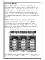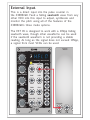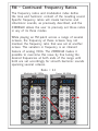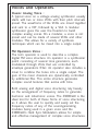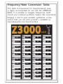
1
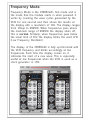
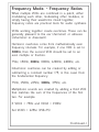
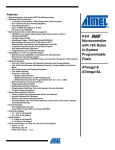
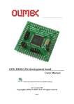
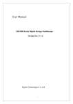
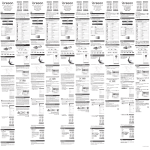
MKII + ++ Z3000 FREQUENCY Smar t VC -O sc i ll a t or Hz Oct FINE TUNE LOW HIGH PULSE WIDTH PWM MIN MAX FM MIN + FREQUENCY/NOTE/OCTAVE HIGH LOW MAX 1V/Oct EXT-IN CV IN INPUT SYNC HSM INPUT INPUT PWM FM 1 CV IN INPUT Linear FM FM 2 WAVE SHAPER INPUT Tipt p A u d i o ++ Z3000 Smart VCOmkII Design - Gur Milstein Special Thanks Matthew Davidson Shawn Cleary Richard Devine Bobby Voso Rene Schmitz Mark Pulver Gene Zumchack Surachai Andreas Schneider MADE IN THE USA Tiptop Audio 2010 All Rights Reserved Welcome. This quick start guide provides an introduction to the operation of the Z3000mkII. The Z3000mkII is an analog voltage controlled oscillator with a built-in digital pulse counter. It displays constant pitch data at a refresh rate of one update per second in three different modes. Each mode can be accessed using the Mode Switch. This unique feature puts the Z3000mkII into a class of its own as a VCO, bringing new capabilities of complex sound synthesis to the analog realm. In addition, it simplifies the setup of multi-oscillator voices by allowing pitch intervals to be set by sight. + + Z3000 FREQUENCY Sm Ossc ciill or S m art ar t VC V C --O l lat a to Hz Oct Mode Switch 1. Frequency Mode 2. Musical Note Mode 3. Octave Mode LOW LOW FINE TUNE FINE TUNE HIGH HIGH LOW LOW PULSE WIDTH WIDTH PWM MIN MIN MIN MIN + FREQUENCY/NOTE/OCTAVE FREQUENCY/NOTE/OCTAVE HIGH HIGH FM FM MAX MAX MAX MAX 1V/Oct 1V/Oct EXT-IN CV IN CV OUT INPUT SYNC HSM INPUT INPUT INPUT INPUT PWM FM 1 CV CV IN IN INPUT INPUT Linear Linear FM FM FM FM 2 2 WAVE EXT IN SHAPER INPUT INPUT INPUT Tipt p A A u u d d ii o o + Frequency Mode. Frequency Mode is the Z3000mkII’s first mode and is the mode that the module starts in when powered. It works by counting the wave cycles generated by the VCO for one second and then shows the results on the display with a resolution of 1Hz. The display ranges from 1Hzup to 9999Hz. When frequencies pass above the maximum range of 9999Hz the display shuts off, this is normal. Similarly, when frequencies pass below the lower limit of 1Hz the display blinks the word LFO (Low Frequency Oscillator). The display of the Z3000mkII is fully synchronized with the VCO frequency and blinks accordingly at low frequencies. Each time the display comes on, it indicates the start of a new wave. This is especially useful at low frequencies when the VCO is used as a clock generator or LFO. LFO 1Hz + 9999Hz Display Off + Z3000 FREQUENCY FREQUENCY + Hz Hz HIGH HIGH LOW PULSE PULSE WIDTH WIDTH PWM PWM MIN MIN MAX MAX FM FM MIN MIN + Oct FREQUENCY/NOTE/OCTAVE FREQUENCY/NOTE/OCTAVE HIGH HIGH FINE TUNE TUNE MAX MAX Sm art ma rt V C -O sc s c i ll l l ator at o r Hz Oct Oct LOW + Z3000 FREQUENCY S ma rt V C -O ssc c i l lat Sm art C-O l ator or 1V/Oct 1V/Oct EXT-IN CV CV IN IN CV OUT INPUT SYNC HSM INPUT INPUT INPUT INPUT PWM FM 1 CV CV IN IN INPUT INPUT Linear FM FM 2 WAVE SHAPER EXT IN A A uu dd ii oo FINE TUNE TUNE HIGH HIGH LOW PWM PWM MIN MAX MAX FM MIN + + FREQUENCY/NOTE/OCTAVE HIGH HIGH PULSE PULSE WIDTH WIDTH INPUT INPUT INPUT Tipt p LOW MAX MAX 1V/Oct 1V/Oct EXT-IN CV IN CV OUT INPUT SYNC HSM INPUT INPUT PWM FM 1 CV IN INPUT Linear FM FM 2 WAVE SHAPER EXT IN INPUT INPUT INPUT Tipt p A u d i o + ʨ˔ˇ˓˗ˇː˅˛ʯˑˆˇʎʐʨ˔ˇ˓˗ˇː˅˛ʴ˃˖ˋˑ˕ ʹˊˇːˏ˗ˎ˖ˋ˒ˎˇʸʥʱ˕˃˔ˇ˅ˑˏ˄ˋːˇˆˋː˃˒˃˖˅ˊʏˇˋ˖ˊˇ˔ ˏˑˆ˗ˎ˃˖ˋːˉˇ˃˅ˊˑ˖ˊˇ˔ʏˏˑˆ˗ˎ˃˖ˋːˉˑ˖ˊˇ˔ˏˑˆ˗ˎˇ˕ʏˑ˔ ˕ˋˏ˒ˎ˛ˊ˃˘ˋːˉ˖ˊˇˋ˔˙˃˘ˇˈˑ˔ˏ˕ˏˋ˚ˇˆ˖ˑˉˇ˖ˊˇ˔ʏ ˈ˔ˇ˓˗ˇː˅˛˔˃˖ˋˑ˕˃˔ˇ˒˔˃˅˖ˋ˅˃ˎ˖ˑˑˎ˕ˈˑ˔˃˗ˆˋˑ˕˛ː˖ˊˇ˕ˋ˕ʎ ʸʥʱ˕˙ˑ˔ˍˋːˉ˖ˑˉˇ˖ˊˇ˔˅˔ˇ˃˖ˇˑ˘ˇ˔˖ˑːˇ˕ʎʶˊˇ˕ˇ˅˃ː˄ˇ ˉˇːˇ˔˃ˎˎ˛˒ˎˇ˃˕˃ː˖˖ˑ˖ˊˇˇ˃˔ʊˊ˃˔ˏˑːˋ˅ʋˑ˔˃˄˔˃˕ˋ˘ˇ ʊˋːˊ˃˔ˏˑːˋ˅ˑ˔ˆˋ˕˕ˑː˃ː˖ʋʎ ʪ˃˔ˏˑːˋ˅ˑ˘ˇ˔˖ˑːˇ˕˅ˑˏˇˈ˔ˑˏˏ˃˖ˊˇˏ˃˖ˋ˅˃ˎˎ˛ˇ˘ˇː ˈ˔ˇ˓˗ˇː˅˛ˋː˖ˇ˔˘˃ˎ˕ʎʨˑ˔ˇ˚˃ˏ˒ˎˇʏˋˈˑːˇʸʥʱˋ˕˕ˇ˖˖ˑ ʕʒʒʪ˜ʏ˖ˊˇː˖ˊˇ˕ˇ˅ˑːˆʸʥʱ˕ˊˑ˗ˎˆ˄ˇ˕ˇ˖˖ˑ˃ː ˇ˘ˇːˏ˗ˎ˖ˋ˒ˎˇˑ˔ˈ˔˃˅˖ˋˑːʜ ʙʗˊ˜ʏʓʗʒʪ˜ʏʕʒʒʪ˜ʏʘʒʒʪ˜ʏʓʔʒʒʪ˜ʏʔʖʒʒʪ˜ʏˇ˖˅ʎ ʫːˊ˃˔ˏˑːˋ˅ˑ˘ˇ˔˖ˑːˇ˕˅˃ː˄ˇ˅˔ˇ˃˖ˇˆ˄˛˃ˆˆˋːˉˑ˔ ˕˗˄˖˔˃˅˖ˋːˉ˃˅ˑː˕˖˃ː˖ː˗ˏ˄ˇ˔ʊʙʗʏˋː˖ˊˋ˕˅˃˕ˇʋˈ˔ˑˏ ˖ˊˇˈ˗ːˆ˃ˏˇː˖˃ˎˈ˔ˇ˓˗ˇː˅˛ʜ ʙʗʪ˜ʏʓʗʒʪ˜ʏʔʔʗʪ˜ʏʕʒʒʪ˜ʏʕʙʗʪ˜ʏˇ˖˅ʎ ʯ˗ˎ˖ˋ˒ˊˑːˋ˅˕ˑ˗ːˆ˕˃˔ˇ˅˔ˇ˃˖ˇˆ˄˛˃ˆˆˋːˉ˃˖ˊˋ˔ˆʸʥʱ ˖ˊ˃˖ˏ˃˖˅ˊˇ˕˖ˊˇ˕˗ˏˑˈ˖ˊˇˈ˔ˇ˓˗ˇː˅ˋˇ˕ˑˈ˖ˊˇˈˋ˔˕˖ ˖˙ˑʎʨˑ˔ˇ˚˃ˏ˒ˎˇʜ ʫˈʸʥʱʓʟʙʗʪ˜˃ːˆʸʥʱʔʟʓʗʒʪ˜ ʵˇ˖ʸʥʱʕʟʔʔʗˊ˜ʊʓʗʒʍʙʗʋ ʊʥˑː˖ˋː˗ˇˆʎʎʎʋ Frequency Ratios. - Continued Audio synthesis relies heavily on frequency ratios, so using them appropriately can be very helpful no matter what the application: modulate the pulse width of another VCO, for frequency modulation, modulate the cutoff of a filter or any other parameters in a given system’s modules. The Z3000mkII’s Frequency Mode makesit possible to quickly experiment with the mathematical side of sound design and audio processing. The Music Note Mode allows for the same techniques but from a different perspective. It allows frequency ratios to be set easily but based on the harmonic relationships of musical notes as defined by the chromatic scale. This feature allows those with extensive training in music theory to experiment with sound design and composition on a modular synthesizer by setting those ratios. Try experimenting with different sounds by setting multiple Z3000mkIIs to different musical notes and have them modulate one another. Extended Frequency Range. FREQUENCY LOW HIGH The Z3000mkII has been given an expanded frequency range above and below its predecessor. It now covers the range of 0.7Hz all the way up to 30kHz. This higher top end, for example; is especially useful for the Clock Input of our Z-DSP VC-Digital Signal Processor module. Musical Note Mode. The Musical Note Mode works by comparing the VCO frequency to a table of stored values corresponding to Western musical notes. In this mode, the display will show the numerical frequency reading, but once a specific frequency is reached that is equivalent to a known note value, the display will show the name of the note. For example, if the VCO is tuned for 53Hz it will display '53', but if the pitch were to reach 55Hz the display will show 'A1' which is the musical note A of octave 1. A Note-to-Frequency chart is available online and at the end of this guide. Sharp notes are represented by a dot between the note and octave number. Dot Indicates Sharp Note C.2 d.2 =%) F.2 G.2 A.2 C2 d2 E2 F2 G2 A2 b2 Musical Note Mode. - Chords Musical Note Mode is very useful for creating tonal music with a modular synthesizer. It allows multiple VCOs to be set to specific notes or semitones, space several Z3000mkIIs apart to build chords, or set any VCOs to a specific musical key to match a music piece. For example, using three Z3000mkIIs, it is possible to set a basic C major chord consisting of notes C, E, and G. Chord charts are available from many music retailers. C.2 d.2 F.2 G.2 A.2 C Major Chord C2 d2 E2 F2 G2 A2 b2 Set three Z3000mkIIs to the following notes. Stack their 1v/o inputs from a common out, then mix their audio outs. Try sending each voice, or a mix of all three, through a VCF controlled by an envelope generator. + FINE TUNE LOW HIGH PULSE WIDTH PWM MIN MAX FM + MAX + + Z3000 FREQUENCY S mart VC -Os cil l ator S mar t VC - O sci ll ato r + S mar t V C- O sci l lat or Hz Hz Hz Oct Oct FREQUENCY/NOTE/OCTAVE 1V/Oct EXT-IN CV IN INPUT SYNC HSM INPUT INPUT PWM FM 1 CV IN INPUT Linear FM FM 2 WAVE SHAPER A u d i o FINE TUNE LOW HIGH PULSE WIDTH PWM MIN MAX FM INPUT Tipt p MIN + + FREQUENCY/NOTE/OCTAVE HIGH LOW MAX 1V/Oct EXT-IN CV IN INPUT SYNC HSM INPUT INPUT PWM FM 1 CV IN INPUT Linear FM FM 2 WAVE SHAPER A u d i o FINE TUNE LOW HIGH PWM MIN MAX FM MIN + + FREQUENCY/NOTE/OCTAVE HIGH LOW PULSE WIDTH INPUT Tipt p + Z3000 FREQUENCY Oct HIGH LOW MIN + Z3000 FREQUENCY MAX 1V/Oct EXT-IN CV IN INPUT SYNC HSM INPUT INPUT PWM FM 1 CV IN INPUT Linear FM FM 2 WAVE SHAPER INPUT Tipt p A u d i o + Octave Mode. Octave Mode improves upon the functionality of a mechanical octave switch. With an ordinary VCO in a modular system, setting the relationship between the note pressed on a keyboard and what is heard is often requires an independent reference at a known pitch, usually a non-modular synth. The Octave Mode of the Z3000mkII makes this task a quick and efficient process. While in Octave Mode, the display will show the relative octave of the note being heard (“OCt2”, “OCt3”, etc). As the pitch approaches a C in any octave, the display will change and show how close the pitch is to the defined note within 50 cents on either side of the note. Oct0 Oct1 Oct2 Oct3 Oct4 Oct5 Oct6 Oct7 C0 C1 C0 + FINE TUNE LOW HIGH PULSE WIDTH PWM MIN MAX FM + MAX C4 + C5 + Z3000 FREQUENCY S m a rt V C -Os ci l l at or Sm a rt VC -O s c i ll at or C6 + C7 C7 Sm a rt V C -O s c i ll at or Hz Hz Hz Oct Oct FREQUENCY/NOTE/OCTAVE 1V/Oct EXT-IN CV IN INPUT SYNC HSM INPUT INPUT PWM FM 1 CV IN INPUT Linear FM FM 2 WAVE SHAPER A u d i o FINE TUNE LOW HIGH PULSE WIDTH PWM MIN MAX FM INPUT Tipt p MIN + C2 - 50 cents + FREQUENCY/NOTE/OCTAVE HIGH LOW MAX 1V/Oct EXT-IN CV IN INPUT SYNC HSM INPUT INPUT PWM FM 1 CV IN INPUT Linear FM FM 2 WAVE SHAPER A u d i o C2 FINE TUNE LOW HIGH PWM MIN MAX FM MIN + + FREQUENCY/NOTE/OCTAVE HIGH LOW PULSE WIDTH INPUT Tipt p + Z3000 FREQUENCY Oct HIGH LOW C3 + Z3000 FREQUENCY MIN C2 MAX 1V/Oct EXT-IN CV IN INPUT SYNC HSM INPUT INPUT PWM FM 1 CV IN INPUT Linear FM FM 2 WAVE SHAPER INPUT Tipt p A u d i o + C2 + 50 cents This allows you to quickly match the CV note input to the actual pitch of the oscillator. (Continued...) Octave Mode. - Continued Setting up the Z3000mkII to use Octave Mode is simple. First, configure a keyboard through a MIDI to CV converter and plug the CV output of the converter into the 1V/OCT input on the Z3000.mkII. + + Z3000 FREQUENCY S ma rt V C-O sc illato r Hz Oct FREQUENCY/NOTE/OCTAVE HIGH LOW FINE TUNE 1V/Oct EXT-IN CV IN INPUT SYNC HSM INPUT INPUT PWM FM 1 CV IN INPUT Linear FM FM 2 WAVE SHAPER MIDI TO CV LOW HIGH PULSE WIDTH PWM MIN MAX FM MIN + MAX INPUT Tipt p A u d i o + Now, set the Z3000 into Octave Mode by pressing the FREQUENCY/NOTE/OCTAVE button. Press any low ‘C’ key on the keyboard and use the FREQUENCY and FINE TUNE knobs to adjust the pitch of the Z3000mkII until the desired C note is shown on the display. Remember, as the frequency approaches the octave, the display will show “-Cx” or “Cx-” to show if the module is below or above the pitch of the actual note. 1V/Oct CV Input The Z3000mkII’s 1V/Oct CV Input has a very high resistance-input designed to allow you to stack CV signals from a CV source before entering the unit without encountering tuning error, or “CV Drop.” With the the release of our Stackcables there was no longer a need for a built in CV mult. The available space made it possible to bring out the waveshaping ability. The Waveshaper Input is described further in this manual on page 14-2. TM + CV IN FINE TUNE HIGH LOW PULSE WIDTH PWM MIN MAX FM MIN + MAX + Smart VC-O sci llator S m art VC-Osc i llat or Hz Hz Oct FREQUENCY/NOTE/OCTAVE 1V/Oct EXT-IN CV IN INPUT SYNC HSM INPUT INPUT PWM FM 1 CV IN INPUT Linear FM FM 2 WAVE SHAPER CV Stack A u d i o FINE TUNE HIGH LOW PULSE WIDTH PWM MIN MAX FM INPUT Tipt p CV IN MIN + + FREQUENCY/NOTE/OCTAVE HIGH LOW 1V/Oct + Z3000 FREQUENCY Oct HIGH LOW 1V/Oct + Z3000 FREQUENCY MAX 1V/Oct EXT-IN CV IN INPUT SYNC HSM INPUT INPUT PWM FM 1 CV IN INPUT Linear FM FM 2 WAVE SHAPER INPUT Tipt p A u d i o It should be known that the CV bus can be enabled using the HD2 jumper on the main PCB. Further, this will not override the 1V/Oct CV input on the front panel. + External Input. This is a direct input into the pulse counter in the Z3000mkII. Feed a falling sawtooth wave from any other VCO into this input to adjust, synthesize and monitor the pitch using all of the features of the Z3000mkII's three mode options. The EXT IN is designed to work with a 10Vpp falling sawtooth wave, though other waveforms can be used if the sawtooth waveform is not providing a stable reading. As long as the signal does not exceed 10Vpp, a signal from most VCOs can be used. + + Z3000 FREQUENCY VCO S m a r t VC -O - O scillator s c i ll a t o r Smart Hz Oct LOW LOW FREQUENCY/NOTE/OCTAVE HIGH HIGH FINE TUNE TUNE LOW HIGH HIGH PULSE WIDTH WIDTH PULSE PWM MIN MAX FM 1V/Oct 1V/Oct EXT-IN CV IN INPUT CV OUT SYNC HSM INPUT INPUT PWM FM 1 CV IN INPUT Linear FM FM 2 WAVE SHAPER EXT IN Sawtooth MIN + MAX INPUT INPUT INPUT Tipt p A u d i o + Frequency Modulation. - Basics Frequency modulation (FM) synthesis is a technique used to generate musically interesting sounds by rapidly changing the basic frequency of a sound. The pattern of change is created by another waveform with a frequency within the range of human hearing. In practice, it is as simple as connecting the audio output of an oscillator to the frequency control input of another oscillator. First, a number of considerations need to be taken into account: waveform type, FM input type, frequency ratio, and synchronization. Frequency modulation starts with two or more oscillators. The first (the modulator) is used to modulate the frequency of a second oscillator (the carrier). Typically, sine waves are used because they are, ideally, free of harmonics, but modular systems allow for the use of other waveforms. However, the more complex the modulating waveform is the more complex the resulting waveform. Too much complexity and the waveform becomes noise and avoiding this is one of the most significant aspects of FM theory. There are many books that can explain the fundamentals of FM synthesis in greater detail than is possible here. Frequency modulation has been widely used in digital synthesizers thanks to the stability and precise tracking of software-based digital VCOs. The Z3000mkII’s built-in arithmetic processor allows the user to implement true FM in analog, and to build harmonically rich sounds using a calculated synthesis approach. (Continued...) FM - Continued: Modulation Index The amount of modulation applied to the second oscillator is commonly known as the modulation index. The modulation index is controlled by the FM knob on the Z3000mkII. It is difficult to calculate the actual spectrum of the resulting sound created by the modulation index, but the more modulation applied, the more complex the sound gets, resulting in noise and frequency drift. For example, increasing the modulation index of a sine wave modulating another sine wave, the resulting waveform changes from a sine wave at modulation index 0 (FM knob to MIN), through increasingly more complex waveforms, ending with noise at a very high modulation index. The change from sound to noise can be quite sudden, so it should be noted that a small amount of modulation can provide more desirable results. (Continued...) FM ++ ZZ33000000 ++ FREQUENCY FREQUENCY Sm r t VVC a toorr Smaart C-O - Ossccii llllat Hz Hz Oct Oct MIN MAX LOW LOW FREQUENCY/NOTE/OCTAVE FREQUENCY/NOTE/OCTAVE HIGH HIGH FINE FINE TUNE TUNE ‘Safe Zone’ LOW LOW HIGH HIGH PULSE PULSE WIDTH WIDTH PWM PWM MIN MIN MAX MAX FM FM 1V/Oct 1V/Oct 1V/Oct EXT-IN CV CV IN IN CV OUT INPUT SYNC SYNC HSM HSM INPUT INPUT INPUT INPUT PWM PWM FM FM 11 CV CV IN IN INPUT INPUT Linear Linear FM FM FM FM 22 WAVE SHAPER FM Modulation Index MIN MIN ++ MAX MAX INPUT INPUTINPUT Tipt p AA uu dd i i oo + FM - Continued: Input Types The Z3000mkII is equipped with two exponential FM inputs and one linear FM input. The FM1 and FM2 jacks are exponential but FM2 is summed with the Linear FM input and, as such, share the FM knob. Generally speaking, when employing FM theory, linear modulation provides the only true form of modulation and has more predictable results and produces less inharmonic material than exponential FM does. To implement a basic FM patch, plug the sine wave from one Z3000 into the Linear FM input of a second Z3000mkII. Frequency modulated sounds become more complex as more modulators and carriers are added to a patch, whether in series or in parallel. Pairs of modulators and carriers are called “operators” and usually include VCAs and envelope generators to dynamically vary the modulation index over time. (Continued...) ++ Z 33 00 00 00 FREQUENCY Smart C-O S mart VC --O Osci Sm ar t V s c illator ll a t o r LOW LOW LOW HIGH HIGH HIGH PULSE WIDTH WIDTH PULSE PWM PWM PWM MIN MIN MIN MIN MIN MIN ++ FM FM MAX MAX MAX MAX MAX MAX ++ ZZ33000000 FREQUENCY FREQUENCY FREQUENCY Smart VC-Osci S ma r t V - Os ciill lllator l at or Smart VC C-Osc ator Hz Hz Hz Hz Hz Oct Oct Oct Oct Oct FREQUENCY/NOTE/OCTAVE FREQUENCY/NOTE/OCTAVE HIGH HIGH FINE TUNE TUNE + 1V/Oct 1V/Oct 1V/Oct EXT-IN 1V/Oct CV CV IN IN CV OUT INPUT CV OUT SYNC SYNC HSM HSM INPUT INPUT INPUT INPUT PWM PWM FM FM 11 CV CV IN IN INPUT INPUT Linear Linear FM FM FM FM 22 WAVE EXT SHAPER EXT IN IN LOW LOW LOW AA uu dd ii oo A u d i o modulator HIGH HIGH HIGH PWM PWM PWM MIN MIN MIN MIN MIN MIN + +++ FREQUENCY/NOTE/OCTAVE FREQUENCY/NOTE/OCTAVE HIGH HIGH HIGH TUNE FINE FINE TUNE TUNE PULSE WIDTH PULSE PULSE WIDTH WIDTH INPUT INPUT INPUT INPUT INPUT Tipt p LOW LOW LOW FM FM FM MAX MAX MAX MAX MAX MAX ++ 1V/Oct 1V/Oct 1V/Oct 1V/Oct EXT-IN CV IN CV CV IN IN CV OUT INPUT SYNC SYNC SYNC HSM HSM INPUT INPUT INPUT INPUT INPUT INPUT PWM PWM PWM FM FM FM 111 CV IN CV CV IN IN INPUT INPUT INPUT Linear FM Linear Linear FM FM FM 22 FM FM 2 WAVE EXT IN SHAPER INPUT INPUTINPUT INPUT INPUT Tipt p A u d i o AA uu dd i i oo carrier ++ FM - Continued: Frequency Ratios The frequency ratios and modulation index define the tone and harmonic content of the resulting sound. Specific frequency ratios will create harmonic and inharmonic sounds, as previously described, and the Z3000mkII allows the user to precisely set those ratios in any of its three modes. While playing an FM patch across a range of several octaves, the frequency at these octaves may not maintain the frequency ratio that was set at another octave. This variation in frequency is an inherent feature of analog VCOs. The Z3000mkII makes it possible to overcome this issue by fine tuning the desired frequencies at both ends of the range until both are set accordingly for smooth harmonic sounds spanning several octaves. Ratio = 2:1 Modulator @ 130Hz ++ Z3000 FREQUENCY Sm C-O scillator S m art ar t V VC -O s c i lla tor Carrier @ 65Hz + ++ ZZ33000000 FREQUENCY FREQUENCY Smart S ma rt VC-O V C -Oscillator s c il la t o r Hz Hz Hz Oct Oct Oct LOW LOW HIGH HIGH PULSE WIDTH WIDTH PULSE PWM PWM MIN MIN MIN MIN ++ FREQUENCY/NOTE/OCTAVE HIGH HIGH FINE TUNE TUNE FM FM MAX MAX MAX MAX ++ 1V/Oct EXT-IN 1V/Oct CV IN INPUT CV OUT SYNC HSM INPUT INPUT PWM FM 1 CV IN INPUT Linear FM FM 2 WAVE SHAPER EXT IN A u u d d ii o o A FINE FINE TUNE TUNE LOW LOW HIGH HIGH PWM PWM MIN MIN MAX MAX FM FM MIN MIN + ++ FREQUENCY/NOTE/OCTAVE FREQUENCY/NOTE/OCTAVE HIGH HIGH PULSE PULSE WIDTH WIDTH INPUT INPUT INPUT Tipt p LOW LOW MAX MAX 1V/Oct 1V/Oct 1V/Oct EXT-IN CV CV IN IN CV OUT INPUT SYNC SYNC HSM HSM INPUT INPUT INPUT INPUT PWM PWM FM FM 11 CV CV IN IN INPUT INPUT Linear Linear FM FM FM FM 22 WAVE SHAPER INPUT INPUTINPUT Tipt p AA uu dd i i oo + Synchronization and FM. Combining synchronization and frequency modulaton allows for the creation of whole new sound spectra. Its sound is more predictable than FM alone, as there is no chance of the fundamental of the modulating oscillators drifting away when increasing or decreasing the modulation index. As a result, the output sounds are less likely to become inharmonic. Conversely, the synchronization itself distorts the waveform of the slave VCO, thus adding harmonics to the sound. The Z3000mkII offers traditional hard sync along a new type of sync called Hard Sync Modulation (HSM). While traditional hard sync will only work with pulse or sawtooth waves, with similar effect, the HSM accepts any waveform, even complete sounds, which will modulate, distort and rectify the waveform. Hard Sync Modulation is a powerful waveform distortion effect built into the Z3000mkII, and can be used in any patch. + Z3000 FREQUENCY FREQUENCY Sm mart VC- O ss c c ii ll lla orr S ar t V C -O a tt o LOW LOW LOW LOW HIGH HIGH PULSE PULSE WIDTH WIDTH PWM MIN MAX FM MIN + MAX ++ ZZ33000000 FREQUENCY FREQUENCY SSmart ma r t VVC-O C - O sscill ci l l at or ator Hz Hz Hz Hz Oct Oct Oct Oct FREQUENCY/NOTE/OCTAVE FREQUENCY/NOTE/OCTAVE HIGH HIGH FINE TUNE TUNE + 1V/Oct 1V/Oct EXT-IN CV IN CV OUT INPUT SYNC HSM INPUT INPUT PWM FM 1 CV IN INPUT Linear FM FM 2 WAVE EXT IN SHAPER LOW LOW A u d i o master HIGH HIGH PWM PWM MIN MIN MAX MAX FM FM MIN MIN + ++ FREQUENCY/NOTE/OCTAVE FREQUENCY/NOTE/OCTAVE HIGH HIGH FINE FINE TUNE TUNE PULSE PULSE WIDTH WIDTH INPUT INPUT INPUT Tipt p LOW LOW MAX MAX ++ 1V/Oct 1V/Oct 1V/Oct EXT-IN CV CV IN IN CV OUT INPUT SYNC SYNC HSM HSM INPUT INPUT INPUT INPUT PWM PWM FM FM 11 CV CV IN IN INPUT INPUT Linear Linear FM FM FM FM 22 WAVE SHAPER INPUT INPUTINPUT Tipt p AA uu dd i i oo slave + Waveshaper Input. This jack allows the user to inject an external CV or Audio source to modify the symmetry of both the Triangle and Sine waves simultaneously. Thereby adding new character to the sound as it modifies the slightly harmonic Triangle & idealy harmonic-free Sine. The Waveshaper Input accepts +/-5V (the typical VCO waveform output level) allowing for some very extreme waveshaping to take place. Or, if the user pefers; very subtle but effective modulation of the waveforms with the addition of signal attenuation prior to the Waveshaper Input. The Waveshaper accepts signals in the DC range all the way up to audio rate. Allowing for some very animated morphing and mangling of the waves. The result being that you actually add harmonics to the waveform rather than (by the use of filters) take them away. Tips: Adding a VCA before the Wavshaper Input can add more dynamics and control to the amount and timing of the modulation input. CV sequencers help add repeatable, syncronized waveshaping to the mix. Great for when your modulations need to be in sync with a specific tempo. Voices and Operators. Classic Analog Voice - A typical voice on a vintage analog synthesizer usually starts with two or more VCOs with their pitch intervals preset. The wavefroms of the VCOs are mixed together and sent to a VCF, followed by a VCA. A modular synthesizer gives the user the freedom to build complex analog voices. On a modular, a voice is not preset and can be made of several VCOs and other modules. This allows for a variety of synthesis techniques which can be mixed into a single output. FM Operators Voice - The term operator is used to describe a complex digital FM voice structure. An operator is a synthesizer patch consisting of several tone generators, each modulated through VCAs that are controlled by envelope generators (EGs). An operator also includes a mixer to combine the tones into a single output. The gain of the mixer channels are dynamically controlled by additional EGs. This entire structure generates complex sound textures that evolve with time. Both analog and digital voice structuring rely heavily on the arrangement of frequency ratios to generate harmonic and inharmonic voices. The Z3000mkII is the ideal tool for both of these forms of voice structuring, as it allows the user to quickly and easily set the frequency ratios of any of the sound-generating modules being used in a given voice and the Z3000mkII’s Hard Sync Modulation allows for simple and effective management of complex voice structures. Frequency/Note Conversion Table. This table of frequencies for equal-tempered scale is highly recommended for use with the Z3000mkII. Withit, it is possible to navigate frequencies, build chords and construct synthesis models. We recommend hanging it next to your modular synthesizer. A free version that you can print yourself is available at: www.tiptopaudio.com/resources.html G.0 A.0 C.1 D.1 F.1 G.1 A.1 62 B1 F.0 A1 D.0 G1 C.0 F6 A.4 B4 C.5 C5 D5 D7 D.5 E5 F.5 F5 F.7 F7 G5 G7 G.5 G.7 A5 A7 A.5 B5 A.7 B7 3729 D.7 E7 3322 C.7 C7 2960 A.6 B6 2489 G.6 A6 2217 F.6 G6 1865 D.6 E6 1661 C.6 D6 1480 Copyright Tiptop Audio 2008 1046 1175 1319 1397 1568 1760 1976 2093 2349 2637 2794 3136 3520 3951 C6 1245 TM F1 58 E1 55 52 D1 49 46 C1 44 39 B0 41 35 A0 37 29 G0 33 26 F0 31 23 E0 27 19 D0 24 B3 A.3 A3 G.3 G3 F.3 F3 D.3 E3 C.3 C3 A.2 B2 D3 17 C0 22 G.2 21 F.2 18 D.2 92 G.4 A4 932 16 C.2 78 A2 233 98 110 123 131 147 165 175 196 220 247 G2 208 831 F2 185 740 87 156 622 E2 139 524 82 69 D2 73 117 466 C2 F.4 G4 415 65 D.4 F4 C.4 E4 370 C4 311 262 294 330 349 392 440 494 523 587 659 698 784 880 988 D4 104 277 1109 mkII Z3000