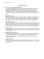
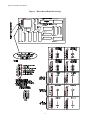
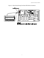
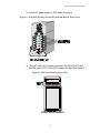
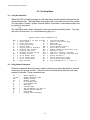
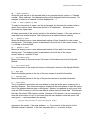
1
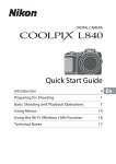
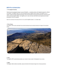
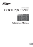
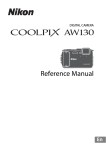
Flow Control User Manual
100 Washington Street, Milford, CT 06460
l
Tel: 203-878-9838
l
Fax: 203-874-0157
World Wide Web: www.lightwavecom.com l email: [email protected]
SystemConsoleSwitch User Manual
Table of Contents
Page
1.0
Product Description ...................................................................................................... 3
2.0
System Overview ........................................................................................................... 4
2.1 Connect up to twelve RS-232C compatible ports.................................................. 4
2.2 Buffered Data Storage.......................................................................................... 4
2.3 Direct and Remote Access ................................................................................... 4
2.4 Security Password ............................................................................................... 4
2.5 Configurable Modem/Auxiliary Port...................................................................... 4
2.6 Parallel Printer..................................................................................................... 4
3.0
System Components...................................................................................................... 5
3.1 Chassis ................................................................................................................ 5
3.2 Spooler Modules .................................................................................................. 5
3.3 External Power Supply ......................................................................................... 5
3.4 System Cable Requirements ................................................................................ 5
4.0
Installation Instructions ................................................................................................ 7
4.1 SystemConsoleSwitch Installation........................................................................ 7
4.2 Daisy-Chaining SystemConsoleSwitches............................................................... 18
5.0
The Help Menu .............................................................................................................. 20
5.1 Using the Help Menu............................................................................................ 20
5.2 Using Channel Commands ................................................................................... 20
5.3 Using Scan Commands ........................................................................................ 22
5.4 Using the Printer Commands ............................................................................... 24
5.5 Using the Direct Mode Command......................................................................... 25
5.6 Name Servers ...................................................................................................... 26
5.7 Other Useful Commands ...................................................................................... 27
The Set-Up Menu........................................................................................................... 28
6.1 Using the Set-Up Menu ........................................................................................ 28
6.1.a Set-Up Menu Reference List.............................................................................. 28
Remote Access.............................................................................................................. 32
7.1 Using Remote Access........................................................................................... 32
7.1.a Remote Access Configurations ................................................................... 32
Modem Initialization................................................................................. 32
Modem Hang-Up String ............................................................................ 32
System Connection/Remote Access Password.......................................... 32
Remote Break-In....................................................................................... 33
Modem Privacy......................................................................................... 34
Technical Support and Warranty Information................................................................. 35
6.0
7.0
8.0
Appendix
Appendix
Appendix
Appendix
A - Component Part Numbers ............................................................................... A-i
B - Trouble Shooting ............................................................................................. B-i
C - Rack Mount SystemConsoleSwitch .................................................................. C-i
D - Flow Control .................................................................................................... D-i
1
SystemConsoleSwitch User Manual
SystemConsoleSwitch User Manual
11/14/97
Copyright 1995 by Lightwave Communications, Inc.
261 Pepe's Farm Road, Milford, Connecticut, 06460, U.S.A.
All rights reserved. No part of this copyrighted material may be reproduced in any form or by any means without
prior written permission from Lightwave Communication, Inc.
Printed in U.S.A.
For more up-to-date information on the SystemConsoleSwitch and
other Lightwave products, visit us on the web:
www.lightwavecom.com
2
SystemConsoleSwitch User Manual
1.0 Product Description
The SystemConsoleSwitch (SCS) allows a user to control and monitor a maximum of 120
devices from a single terminal. Extensive port buffering facilitates trouble shooting by allowing
the user to scroll back and forth through 30* screens (32 Kbytes) of data per port. The remote
access feature allows a user to connect to the SCS and monitor systems from an off-site
location. Password protection ensures access security.
1.1 Features
l
l
l
l
l
l
l
Connect up to twelve RS-232C compatible ports
Daisy-chained units allow connection of up to 120 devices
30 Screens of Buffered Data Storage per Device
Remote Access via Modem Port
Security Password
Configurable Modem/Auxiliary Port
Parallel Printer Port
* The number of data screens will vary, depending on the data displayed.
3
SystemConsoleSwitch User Manual
2.0 System Overview
2.1 Connect up to twelve RS-232C compatible ports
The SystemConsoleSwitch (SCS) is plug compatible with any RS-232 device. Daisychained SystemConsoleSwitches can control up to 120 terminal ports (maximum
recommended). These may be a variety of network servers, routers, and any other
LAN/WAN computers on the network. Access to any one of the connected ports is
achieved through simple keyboard commands (channel selection) through the attached
terminal.
2.2 Buffered Data Storage
Dual Spooler modules allow storage of up to 30 screens (32 Kbytes) of data per device.
Each dual spooler module contains circuitry to support two totally independent devices.
Data storage is continuous for all connected devices. Each SCS is expandable to
accommodate up to six dual spooler modules, allowing 12 devices to be connected.
2.3 Direct and Remote Access
There are two means of access for the SystemConsoleSwitch. One method of access is
through a terminal that is directly connected to the SCS. The alternate method is to use a
dial-up modem from a remote site. Both means of access gives the user the capability to
monitor activity from any connected device, and to interact with each device directly.
2.4 Security Password
The remote access feature requires a password to complete the connection to the SCS.
Should the user fail on their third attempt to enter a password, the SCS will automatically
disconnect the user.
2.5 Configurable Modem/Auxiliary Port
The built in modem port may also be configured to function as an auxiliary terminal port.
This features allows the user to have two consoles (terminals) in different locations.
Switches for the Modem/Aux port may be changed while the power is on, without
interruption to the unit.
2.6 Parallel Printer Port
Another significant feature of the SystemConsoleSwitch is the printer port. The user may
select any portion of the stored data and obtain a hard copy from a printer connected to
the printer port.
4
SystemConsoleSwitch User Manual
3.0 System Components
Each SystemConsoleSwitch consists of three major components, the chassis, spooler
modules and the external power supply.
3.1 Chassis
The chassis contains two circuit boards; the Master Circuit Board and the Switch Board.
Dip switches on the master board allow the SCS to be configured at various baud rates
for the terminal and modem ports (refer to section 4.1, step 2 for detailed instructions).
The Switch Board's main function is device selection, and has no user adjustment. The
chassis is equipped with slots to house up to six dual spooler modules.
3.2 Spooler Modules
Each spooler module contains circuitry to support two totally independent ports. There
are two sets of dip switches on the spooler module for baud rate selection of the
attached device. Each set of dip switches are independently set to be compatible with
its corresponding device. Additionally, dip switches are provided on the spooler module
to select the number of data bits per byte, the number of stop bits, and parity (refer to
section 4.1, step 3 for detailed instructions). It should be noted that each of the dual ports
on the spooler module function independently, both in terms of memory and
communication.
3.3 External Power Supply
Power is supplied to the SCS through a +5V DC power supply, which is plugged into a
grounded 100-250 volt AC outlet.
3.3 System Cable Requirements
Device connections are made with the RJ45 connectors on the rear panel and DB25
male/female as well as DB9 male/female adapters for user equipment.
Figure 1 - SCS Cable Assemblies
5
SystemConsoleSwitch User Manual
This connector style is common to a variety of network cabling schemes and may be
purchased from Lightwave Communications Inc. Refer to Appendix A for cable part
numbers. The following cables connect the terminal, printer, modem, auxiliary and CPU
ports:
l
l
SystemConsoleSwitch to Terminal: Use a straight 1:1 DB25 to DB25 cable (P/N
200.0126, supplied with unit - 15' included, contact your representative if a different
length is needed).
SystemConsoleSwitch Parallel Port to Parallel Printer: Use a parallel printer
cable.
l
SystemConsoleSwitch Modem Port to Modem: 1:1 modem cable.
l
SystemConsoleSwitch Modem Port to Terminal: Null modem cable.
l
SystemConsoleSwitch CPU Ports to CPU: Cabling is RJ45. DB25 and DB9 to
RJ45 adapters are available for device connection.
NOTE: Local Area Network (LAN) cables may be used with the SystemConsoleSwitch
because they are pinned straight through (1:1). Do not use Telephony RJ45 Cables as
they have crossed pinouts and damage to the attached devices or the
SystemConsoleSwitch may occur.
6
SystemConsoleSwitch User Manual
4.0 Installation Instructions
Use the following procedure to install a single SystemConsoleSwitch.
4.1 SystemConsoleSwitch Installation
Refer to Appendix A for Rack Mount SystemConsoleSwitch Diagrams
Step 1: Identify the following items in the shipping container (see figure 2)
l SystemConsoleSwitch Chassis (stand-alone or rack-mount)
l AC power cord
l +5V DC power supply
l Power Supply Cord Retainer Clamp (located on DC power cord)
l DB9 serial cable for cascading the SCS
Important:
Before beginning the installation procedure, re-seat the master board,
Switch Board and each spooler module board, as shipping may
dislodge them.
Figure 2 - DC Power Supply and DB9 Serial Cable
7
SystemConsoleSwitch User Manual
Figure 3 - Master Board Baud Rate Settings
8
SystemConsoleSwitch User Manual
Figure 3a - Master Board Showing Front Panel LED Indicator Attachment
9
SystemConsoleSwitch User Manual
Figure 4 - Spooler Module DIP Switch Locations
(spooler card revision D)
The switch positions below produce
the default communication settings for
the CPU ports (9600 baud, no parity, 8
data bits, 1 stop bit):
LIGHTWAVE COMMUNICATIONS, INC
SYSTEM CONSOLE SWITCH
DUAL PORT SPOOLER MODULE
1 - off
2 - on
3 - off
4 - on
5 - on
6 - off
7 - on
8 - on
SW2 - even numbered ports
SW1 - odd numbered ports
/ROCKER DOWN
O
F
F
1
2
3
4
5
6
7
8
flow control
stop bits
data bits
parity
baud rate
The DIP switches on the previous versions of the spooler card were rotated 180 degrees. Position
one was on the left with on towards the connector10and off towards the edge handle.
SystemConsoleSwitch User Manual
Figure 4a - Spooler Module Dip Switch Settings
ON
ON
ON
ON
ON
ON
ON
ON
ON
ON
ON
ON
ON
ON
ON
11
ON
SystemConsoleSwitch User Manual
Step 2: Master Board Dip Switch Settings The terminal connected to the terminal port
must be a dumb terminal. Some emulation examples are a VT100 or WY60.
If the factory default settings are used, then steps a, b, c below may be
skipped. The default settings are shown in figure 3.
a) Set terminal baud rate
Dip Switches 7 and 8 set the terminal baud rate from 2400 baud to
19.2K baud. The default baud rate settings are: 19.2K baud, no
parity, 8 data bits, and 1 stop bit. Setting the baud rate on the terminal
to match the factory defaults is the best approach. To reset these
switches at a rate other than the factory default setting, first remove
the top section of the front panel, or on Rack Mount units remove the
smoked glass cover. Once the top plate has been removed, the dip
switches are visible. The switches are numbered from left to right, 1-8,
or bottom to top on Rack Mount units. Dip switch 6 selects either X0N/XOFF
or RTS/CTS flow control. The factory default is X0N/XOFF (refer to figure 3)
Note: The power LED indicator is attached to the top section of the
front panel. After completing the baud rate selection, re-connect the
black lead on the power LED indicator to the right-hand side of the two
pin connector on the Master Board (refer to figure 3a).
b) Set Modem/Aux Port Mode
Determine whether the Modem/Aux Port is to be used with a modem or
as an auxiliary port. Dip switch 1 sets this feature. When switch 1 is
in the on position, the port is configured to operate with a modem.
When switch 1 is in the off position, the port is configured to operate
with a terminal (refer to figure 3).
c) Set Modem/Aux port Baud Rate
After determining whether the port is to be used with a modem or a
terminal, set the baud rate for the connected device. Dip switches
4 and 5 set the baud rates from 2400 baud to 19.2K baud (refer to
figure 3). Dip switch 3 selects either X0N/XOFF or RTS/CTS Flow Control.
Factory default is X0N/XOFF.
Note: When in the aux or modem mode, it is not necessary to have
the terminal and the auxiliary port baud rates set the same.
d) After completing steps a, b, and c above, replace the top plate cover
on stand-alone units, or smoked glass cover on Rack Mount units.
Remember on stand-alone units to connect the front panel power
12
SystemConsoleSwitch User Manual
indicator LED with the black wire to the right-hand side of the two pin
connector (refer to figure 3a).
Step 3: Spooler Module Installation
The spooler modules (see figure 5) are installed in the chassis at the factory,
with the default baud rate settings of: 9600 baud, no parity, 8 data bits and 1
stop bit, with XON/XOFF Flow Control. If this setting is compatible with the
attached device, this section may be skipped.
Figure 5 - Spooler Module
a) Remove the lower front panel of the chassis by loosening the two
thumb screw fasteners located at the base of the SCS. On Rack Mount
Units, remove the smoked glass cover. Gently remove
the spooler cards by grasping the handle and pulling straight out.
b) Set dip switches (SW1 and SW2) for the desired baud rate of the
attached device (refer to figure 4). Dip switches 1 and 2 on SW1 and
SW2 correspond to baud rate settings. Dip switches 3, 4, and 5 correspond to the parity of the attached devices. Dip switch 6 is for seven
or eight data bits/bytes. Dip switch 7 is for the number of stop bits.
Dip switch 8 is for Flow Control. Factory default is XON/XOFF Flow Control.
Figures 4 and 4a show the location and definition of the switches. It is
important to make note of the settings of the spooler modules prior to
attaching devices to the SCS. This will ensure that each device is attached to
the proper channel with the correct settings.
c) After the spooler modules are configured, they can be installed in the
chassis.
It is not necessary to turn off power when installing spooler modules.
To re-install the modules, locate the first available set of card guides (slots)
below the switch board module (see figure 6). On Rack Mount Units,
13
SystemConsoleSwitch User Manual
locate the first available set of card guides (slots) to the right of the switch
board module (see figure 6a). It should be noted that the last set of slots in
the chassis (stand-alone units only) are not used. Slide the module,
component side up and connector first, into the card guides. Components
should face the Master Board. Be sure the connector is seated completely
into the chassis connector. Repeat this procedure to re-install all of your
spooler modules (the maximum number of spooler modules per chassis is
six).
Step 4: Connecting devices to the SCS
a) After configuring the master board module and all of the spooler
Figure 6 - SCS with front cover remove
modules for the proper settings, connect the devices to the
spooler modules. Having noted the settings of each channel for the
appropriate spooler modules, the devices are ready to be connected.
Refer to figure 7 and Appendix A for further details regarding proper
pinouts for connection.
b)
Connect the terminal to the SCS using a 1:1 DB25 cable (P/N 200.0126,
supplied with unit).
14
SystemConsoleSwitch User Manual
Figure 6a - Rack Mount SCS with smoked glass cover removed
c)
Connect the parallel printer to the SCS using a standard printer cable
(see Appendix A).
d)
Connect the Modem to the SCS using a modem cable. If an auxiliary
terminal is used on this port, use a null modem cable (See Appendix A).
Step 5: Connecting Power
a) Attach DC power supply cord to SCS with retainer clamp. If the retainer clamp is not already attached to the cord, spread the retainer
clamp and insert the cord through the clamp, then insert retainer
clamp into the hole next to the DC Power Plug connector (see
figure 8).
15
SystemConsoleSwitch User Manual
Figure 7 - SCS Connector Pinouts
16
SystemConsoleSwitch User Manual
b) Attach DC power supply to SCS (refer to figure 8)
Figure 8 - SCS Back Showing Green LEDs and Attached DC Power Cord
c) Plug AC cord into a properly grounded 100-250 volt AC outlet
and the green LED on the top front panel will light (see figure 9).
Figure 9 - SCS Front Showing Green LED
17
SystemConsoleSwitch User Manual
d)
Check the rear panel of the SystemConsoleSwitch to be certain
the Spooler Modules are installed correctly. The rear panel LEDs
should be on when spooler modules are installed. With the lower
front cover removed, verify that all of the green LED's on the
spooler modules are flashing. If any green LED's are not flashing,
re-seat the spooler card with the power on (refer to figure 6).
e)
Replace both top and bottom sections of the front panel.
4.2 Daisy-Chaining SystemConsoleSwitches
Step 1: Connect the control in/out ports of the SystemConsoleSwitches
(see figure 10):
Figure 10 - Daisy-chained SystemConsoleSwitches
a. Using the cable provided, connect the Master "CONTROL OUT"
port to the "CONTROL IN" port of Slave 1.
b. Using another DB9 serial cable connect the "CONTROL OUT"
port of Slave 1 to the "CONTROL IN" port of Slave 2.
18
SystemConsoleSwitch User Manual
c. Follow this procedure until all of the SystemConsoleSwitches
are connected.
The first SCS (connected to the terminal) is referred to as the
Master SCS. All of the SystemConsoleSwitches connected to it
are referred to as "slaves". (see figure 10).
NOTE: Do NOT attach terminal or modem into the slave port,
as erratic behavior will occur.
Step 2: Configure the Slave(s)
From the terminal type
C ↵.
The display will read:
Please wait configuring slaves
Slave 1 configured
Slave 2 configured
"
"
"
"
"
"
"
"
Slave 9 configured
NOTE: If the message prompt
↵ command again.
Slave 1 not found
appears, execute the C
The display will always show the message Slave n not found
(where n = next slave number) on the last line of the display, when
less than 9 slaves are connected. The purpose of this message is to
indicate to the user, that the next slave is nonexistent (there are no
more installed slaves at this point).
19
SystemConsoleSwitch User Manual
5.0 The Help Menu
5.1 Using the Help Menu
When the SCS is initially powered up, the Help menu is automatically displayed on the
connected terminal. The Help Menu is the main level for all other menus in the system.
The Help Menu, entitled "System Console Switch Commands" is accessible at any time
by typing the command:
H ↵
The Help Menu and a brief explanation of the commands are shown below. You may
also print out this menu for convenience by typing PH ↵.
System Console Switch Commands Vx.xx
ALn
Z
CL
C
D
A
H
DL
V
Fn
T
O
E
NA
=
=
=
=
=
=
=
=
=
=
=
=
=
=
Add Channel n to Scan List IM
Clear Queue
Jt
Clear Scan List
N
Configure Slaves
P
Direct Mode
PSn
Display Active Channels
PH
Display Help Screen
RLn
Display Scan List
Rn
Display Spooler Set-Up
SCs
Forward n Lines
SLs
Go To Newest Data
Sn
Go To Oldest Data
Sn
Go To Set-Up Menu
Bl
Name Servers
Mt
=
=
=
=
=
=
=
=
=
=
=
=
=
=
Initialize Modem
Jump To tag And Display
Next Page
Previous Page
Print Channel LineS n
Print Help Screen
Remove Channel n From Scan List
Reverse n Lines
SCan All Channels (seconds)
SCan List (seconds) Any key Stop
Select Channel n
Select Channel by name
Set Display Page Length
Tag inforMation (t = 1 thru 4)
5.2 Using Channel Commands
Channel commands allow the user to select a channel and view data which is stored in
memory by the spooler module. There are ten commands which allow the user easy
access to the data. These commands are:
Sn
=
S name =
FN
=
Rn
=
T
=
O
=
N
=
P
=
Mt
=
Jt
=
Z
=
A
=
Select Channel n
Select Channel by name
Forward n Lines
Reverse n Lines
Go To Newest Data
Go To Oldest Data
Next Page
Previous Page
Tag inforMation (t=1 thru 4)
Jump To tag And Display
Clear Queue
Display Active Channels
20
SystemConsoleSwitch User Manual
SN
=
Select Channel n
Allows the user access to the spooled data for a connected device, where n = Channel
number. When selected, the channel number will be displayed before the prompt. For
example, a selection of channel 2 will be displayed as: 2>
S name
=
Select Channel by name
To select a channel by its name, use the S command, but instead of a number, enter a
space then a server name. Names are limited to 20 characters. . All names are
converted into upper case.
All other commands in this section pertain to the selected channel. If the user wishes to
view data from another channel, that channel must be selected before viewing.
Fn
=
Forward n Lines
Moves the display cursor a user-determined number of lines forward to a new screen
starting point. The display pointer is referenced to the first line of the current screen. The
n = number of lines forward.
Rn
=
Reverse n Lines
Moves the display cursor a user-determined number of lines back to a new screen
starting point. The display pointer is referenced to the first line of the current
screen, where n = number of lines.
T
=
Go To Newest Data
Moves the screen to the most recent full screen of information stored on the Spooler
Module.
O
=
Go To Oldest Data
Moves the screen to the oldest full screen of information stored on the Spooler Module.
N
=
Next Page
Moves the display pointer to the top of the next screen of spooled information.
P
=
Previous Page
Moves the display pointer to the top of the previous screen of spooled information.
Z
=
Clear Queue
The Z command is used when the user wishes to clear the entire queue (memory) for a
specified channel. This command might be used when the user wishes to start the queue
over if the attached devices were re-configured. Memory is organized in such a way that
once the 32K of memory is full, the new data is written over the oldest data. This ensures
that only the newest 32K of data is stored. Because of this feature, it is not necessary to
clear the queue when it is full. In the event that the user wishes to clear the queue, the
user types Z ↵ and immediately the prompt,
Are you sure you want to clear the spooler (Y/N)?
appears on the screen. If the user answers Y↵, the contents of the spooler for the
selected channel is cleared. If the user responds with N↵, no action is taken.
21
SystemConsoleSwitch User Manual
Mt
=
Tag Information (t = 1 thru 4)
Allows the user to mark (tag) up to four locations in a spooler data field (32K spooled
data) for future access. Valid numbers range from 1 through 4, where t = tag number. To
set these tags, the user scrolls through the data and determines where a tag should be
placed. The location of the tag is always at the beginning of the first line of data at the top
of the screen. Once the location has been determined, the user types Mt ↵, where "t"
is the tag number from 1-4. After the tags have been set the user types Jt ↵ to jump to
the location of this tag.
Jt
=
Jump To tag and Display
Allows the user to access up to four different locations in the spooler text. When
selected, the display pointer will move to the user-predetermined point in the text. Valid
numbers range from 1 through 4, where t = the tag number. Because of the amount of
data that can be stored in the spooler modules (32K), this is a feature that allows the user
to tag certain locations in the 32K field of data and quickly jump from one tag location to
another.
A
=
Display Active Channels
Displays installed spooler modules. This is a helpful command that displays all of the
installed spooler modules in a system.
5.3 Using Scan Commands
A unique feature of the SCS is the capability to scan through a list of channels. First, the
user builds a list of frequently used channels. Then, using the Scan List command, the
user can view the latest screen of spooled data for each channel.
The scan list may contain any or all of the active channels. A scan list may be created,
edited, displayed, and cleared. The user may program the SCS to scan through channels
at a specified time interval (in seconds).
There are five commands associated with channel scanning. They are:
ALn
CL
Rln
DL
SCs
SLs
=
=
=
=
=
=
Add Channel n to Scan List
Clear Scan List
Remove Channel n From Scan List
Display Scan List
SCan All Channels (seconds)
SCan List (seconds) Any key Stop
22
SystemConsoleSwitch User Manual
ALn
=
Add Channel n to Scan List
To build a scan list, the user types ALn ↵ where n is the active channel number. Each
active channel must be input separately. For example, to create a scan list for channels
1,2,3, and 4, the user would type:
AL1
AL2
AL3
AL4
DL
=
↵
↵
↵
↵
Display Scan List
To examine the scan list that was created, the user types DL ↵ and the channels in the
list are displayed and separated by commas.
CL
=
Clear scan List
If at any time the user wishes to clear the entire scan list for any reason, the CL
command may be executed. This command will clear the entire scan list. The user is
prompted with:
Are you sure you want to clear the scan list (Y/N)?
If the user answers y ↵, then the list is cleared. If the user answers
is taken by the SCS.
SCs
=
n ↵,
then no action
Scan All Channels (seconds)
If the user wishes to scan all the active channels in the SCS, the user would type
SC10 ↵ . This command would display the present information of all the installed user
connected devices at a 10 second interval between screen updates. The time increments
are user-specified, where s = seconds. Press any key to stop the scan.
SLs
=
Scan List (seconds) Any Key Stop
If the user wishes to use a scan list, the user would type SL10 ↵. This command would
display the present information of the installed user connected devices in the scan list, at
a 10 second interval between screen updates. The time increments are user-specified,
where s = seconds from 1 - 20. Press any key to stop the scan.
RLn
=
Remove Channel n From Scan List
To remove an active channel from the scan list, the user types RLn ↵. This command
will remove the specified channel from the list.
23
SystemConsoleSwitch User Manual
5.4
Using the Printer commands
There are two printer commands on the SCS. One command allows the user to print the
Help Menu, and the other command allows a printout of spooled information for any
channel.
The print commands are:
PSn
PH
PH
=
=
=
Print Channel LineS n
Print Help Screen
Print Help Screen
Prints the Help Menu, whether it is displayed or not.
PSn
=
Print Channel LineS n
The user must first select the channel he wishes to print from. The PSn command causes
"n" lines of spooled data for the specified channel to be printed. For example, to print out
8 lines of data, the user would type:
PS8 ↵
The data to be printed will start at the top of the currently displayed page.
After the PSn command has been entered, the user is given the option of setting printer top
of form. The SCS displays:
Set Printer Top of Form (Y/N)?
If the user wishes to set the top of form, enter Y ↵. This will reset the
SystemConsoleSwitch's internal line count. Physically reset printer paper as necessary,
and perform printer top of form procedures. This will vary from printer to printer.
24
SystemConsoleSwitch User Manual
5.5
D
Using the Direct Mode Command
=
Direct Mode
The Direct Mode is used to directly access the device attached to a channel port. The
SCS is transparent in this mode and the terminal behaves as if it is directly connected to
the attached device.
First select the channel for Direct Mode by typing
Sn ↵ .
Use the following command to enter Direct Mode D↵.
The SCS responds by displaying:
Entering direct mode
All keys typed from the terminal in Direct Mode go directly to the attached device. Any
output from the device will be displayed on the terminal, as well as stored in the channel's
memory.
To exit Direct Mode and return to Monitor Mode you must use the Direct Mode Escape
Sequence command. The default escape sequence is accessed by:
Press and release <Esc>
Followed by pressing and releasing A
This command is case sensitive and is the only command the SCS will respond to in
Direct Mode. The default escape sequence may be modified by the user via the Set-Up
Menu, selection 8. The escape sequence is trapped by the SCS and not transmitted to
the attached device.
NOTE: Any time the spooler memory may contain sensitive data while in Direct
Mode, the user may wish to clear the queue to erase any sensitive data.
NOTE: When the SCS is in the Direct Mode, data that is received from
the connected device may overrun the buffer in the master board. To avoid
this condition, set the baud rate of the terminal higher than the maximum
baud rate of any connected device.
25
SystemConsoleSwitch User Manual
5.6 Name Servers
The NA command brings up the current list of server names. These names are stored in
non-volatile memory, which maintains them, even if power is lost.
The Name Servers feature allows the user to assign a name to a channel number, and
then that name will appear in place of the channel number. The user can also use the
name to select a channel. Of course, the channel number can still be used.
SystemConsoleSwitch Server Names
1 SATURN
2 JUPITER
3 EARTH
4 PLUTO
5 NEPTUNE
6 VENUS
7 MARS
8 ZEUS
9 APOLLO
10 30
11 31
12 32
13 33
14 34
15 35
16 36
17 37
18 38
19 39
20 40
21
22
23
24
25
26
27
28
29
50
51
52
53
54
55
56
57
58
59
60
41
42
43
44
45
46
47
48
49
'O' for other page, 1-120 edits, 'z' clears all, 'P' prints, 'E' exits
Option:
will toggle the display between the first and second group of 60 channels
will clear all server names from the list
'P' will print the entire list to the printer
'E' returns the user to the main level
'O'
'Z'
Entering a number from 1 through 120 will allow the user to enter a name to be
associated with that channel number. Names are converted into upper case.
When a list of active channels, or a scan list is displayed, the channel number is shown in
square brackets '[ ]' following the channel name. This is done to aid in identifying
channels. If no name is assigned to a channel, then the channel is displayed.
Example of 'A' command: SATURN [1], JUPITER [2],3-4, MARS[7]-8
26
SystemConsoleSwitch User Manual
5.7 Other Useful Commands
C = Configure Slaves
Used when daisy-chaining SystemConsoleSwitches.
From the terminal type
C ↵.
The display will read:
Please wait configuring slaves
Slave 1 configured
Slave 2 configured
"
"
"
"
"
"
Slave 9 configured
NOTE: If the message prompt
C ↵ command again.
E
=
Slave 1 not found
appears, execute the
Go To Set-Up Menu
Allows user access to the Set-Up Menu, which will display a variety of items for system
configuration purposes. The Set-Up Menu is accessible through the modem/aux port
when configured as an auxiliary terminal, but not accessible through the modem/aux port
when configured as a modem. The Set-Up Menu is explained in further detail in section
6.0.
Bl
=
Set Display Page Length
Determines the number of available lines in a display, where l = number of lines to be
displayed. To set the page length, subtract one line from the total available number of
lines on your display. The last line at the bottom of the screen is reserved for the SCS
command prompt. The default value is set at 23.
IM
=
Initialize Modem
Verifies modem connection with the SCS sends initialization information to the modem.
Use this command after a modem has been installed (refer to section 7).
H
=
Display Help Screen
Displays the Help Screen.
V
=
Display Spooler Set-Up
Displays the Version number of both the spooler and master modules. In addition, the
baud rates of the spooler, terminal, and modem are displayed. The state of RTS, DTR
and Parity are also displayed.
27
SystemConsoleSwitch User Manual
6.0 The Set-Up menu
6.1 Using the Set-Up Menu
The Set-Up Menu is accessible at any time, when not in Direct Mode, by typing
The menu is shown below. A brief explanation of the commands and default settings
is listed after the menu.
E ↵.
SystemConsoleSwitch Set-Up Menu Vx.xx
1)
3)
5)
7)
Terminal CR translation (in) CR
Modem CR translation (in)
CR
Printer CR translation
CRLF
Remote Access Password ****
9)
Modem init. string ATEO VOSO = 1
11) Remote Mode Break-in DISABLED
13) Direct Spooling ENABLED
8)
2) Terminal CR translation (out)
4) Modem CR translation (out)
6) Printer Page Length in lines
Direct Mode Escape Sequence
10) Modem hang-up string ~~~+++~~~
CR
CR
56
1bH A
ATH0
12) Modem Security DISABLED
14) Return to spooler mode
NOTE: ATE0X0V0&A0S0=1 is an init string that works with US Robotic modems.
6.1.a. Set-Up Menu Reference List
All commands are initiated by pressing the ↵ key. Once a command is selected, the user
may exit without making a selection by pressing the <ESC> key three times.
1) Terminal CR translation (in)
This set-up allows the SCS to translate the CR (carriage return) character to a
CR, LF sequence (carriage return, line feed). This translation applies to a CR
generated by the terminal and then processed by the SCS.
2) Terminal CR translation (out)
This set-up allows the SCS to translate the CR output by the SCS to a CR, LF
sequence. This sequence applies to a CR generated by the SCS and then
processed by the terminal.
3) Modem CR translation (in)
This set-up allows the SCS to translate the CR character to a CR, LF sequence.
This translation applies to a CR generated by the modem and then processed by
the SCS.
4) Modem CR translation (out)
This set-up allows the SCS to translate the CR output by the SCS to a CR, LF
sequence. This sequence applies to a CR generated by the SCS and processed
by the modem.
28
SystemConsoleSwitch User Manual
5) Printer CR translation
This Set-Up allows the SCS to translate the CR output by the SCS to the printer
to be translated to CR,LF.
6) Printer Page Length in lines
Sets the number of lines per printing page, according to your printer
specification. The factory default setting is 56.
7)
Remote access password
Use to change access password. A remote user is required to enter a password
before being allowed access to the SCS. After the remote user calls the SCS
and the modem has performed the basic connect function, the user will be
prompted for the remote password. The remote user is allowed up to three
attempts to enter the correct password. If all three attempts fail, the remote
caller is disconnected from the SCS. The SCS is shipped with a temporary
password of PASS. It is important that the current password be remembered.
The password cannot be changed without the current password.
NOTE: Passwords are case sensitive.
To change the password select E ↵ from the Help Menu. The Set-Up Menu will
then display on the terminal. From this menu select 7 ↵ . The terminal will
display:
Please enter password
This must be the current password. As you enter the password, ***** will
appear on the terminal. When the current password has been entered type ↵.
The terminal will display:
Enter Remote Access Password (8 characters maximum)
NOTE: 8 characters maximum includes the termination character ↵, therefore
the active number of characters is 7. Enter your password, keeping in mind that
the password is case sensitive. When the new password has been entered, the
↵ terminates the string. When the SCS accepts the new password, the SCS
returns to the Set-Up Menu. At this point select 14 ↵ to return to the Spooler
Mode. You cannot escape out of this menu selection without entering a
new password. Three escape keys will be interpreted as the new password. If
you wish to exit this section without changing the password, you must attempt to
enter a password incorrectly three times, or type in the old password until the
SCS prompts with, Enter Remote Access Password (8 characters maximum).
At this point, enter the old password and you will return to the Set-Up Menu.
29
SystemConsoleSwitch User Manual
8) Direct Mode Escape Sequence
Allows the user to exit the Direct Mode and return to Monitor Mode. The factory
default Direct Mode Escape Sequence is the <ESC> key followed by a capital A.
NOTE: The Set-Up Menu will display 1bH instead of <ESC>. 1bH is the
hexadecimal representation for the <ESC> key.
To change the Direct Mode Sequence, select E ↵ from the help menu. The SetUp menu will then display on the terminal. From this menu, select 8 ↵ . The
terminal will display:
Current Direct Mode Escape Sequence = XXXXX
Enter Direct Mode Escape Sequence (4 characters maximum)
Enter your new Direct Mode Escape Sequence. This can be any four
characters. Keep in mind that the escape sequence is case sensitive. After
entering a maximum of four characters, type ↵ to display the setup menu and
then select 14 ↵ to exit the setup menu and return to the Monitor Mode.
NOTE: To leave the sequence unchanged, type Escape three times.
9) Modem Initialization String
Sets the SCS for modem connection. Reference your modem handbook for
command definitions. The command strings in the modem handbook and the
SCS modem connection strings must be the same. Set the SCS string to agree
with the modem handbook string. Refer to the Remote Access section for further
details.
NOTE: To leave the sequence unchanged, type Escape three times.
10) Modem Hang-up String
Sets the SCS for modem disconnect. Reference your modem handbook for
command definitions. Refer to the Remote Access section for further details.
NOTE: To leave the sequence unchanged, type Escape three times.
(password required to change settings)
The remote user can attempt to connect to the SCS at any time. If the SCS is not
in the Set-Up Mode or Direct Mode, access is always granted. The SCS action
taken to a call in various modes will be dependent upon the current setting of the
Remote Break-in mode. The mode can be either Enabled or Disabled. Table 1 on
page 33 displays the action and response sequence under the various modes.
Successful Remote Break-in will not occur unless the password is entered
correctly.
11) Remote Mode Break-in
30
SystemConsoleSwitch User Manual
(password required to change settings)
Enabling this command allows the remote user dialog with an SCS port to be
private, not displayed on the terminal connected to the SCS. In order to change
the Modem Security function, the user must know the password.
12) Modem Security
(password required to change settings)
Allows the user to disable Direct Spooling. This feature may be used in
conjunction with Modem Security for additional security; when the remote user
does not want information to be spooled. Disabling Direct Spooling ensures that
information will not be stored through the spooler. In order to change the Direct
Spooling function, the user must know the password.
13) Direct Spooling
14) Return to spooler mode
This command returns the user to the main level.
31
SystemConsoleSwitch User Manual
7.0 Remote Access
7.1 Using Remote Access
The remote access feature of the SCS allows a user access to the SCS from a remote
location. All functions of the SCS are available to the remote user with the exception of
the Set-Up function.
The configurations described below may be set via the Set-Up Mode (refer to section
6.1).
7.1.a.
Remote Access Configurations
Modem Initialization:
Before initializing the modem, check your modem initialization string to see if it matches
the default string used by the SCS. If the modem settings do not match, change the SCS
settings to match the modem. This set-up is available via menu selection 9 of the Set-Up
menu. Note that the SCS will add the V0 clause if the clause does not appear in the
modem initialization string. To send this string to the modem, select the IM (Initialize
Modem) option from the main menu.
NOTE: Make sure the modem is programmed to Auto Answer. Ex. S0=1 will
cause the SCS modem to answer after first ring.
Modem Hang-up String:
The modem hang-up string is sent to the SCS modem when the G (Good-bye) option is
selected. If the modem settings do not match, change the settings to match the modem.
Before sending the G command, check your modem hang-up string to see if it matches
the default string used by the SCS. The default string of ASCII characters necessary to
cause a modem hang up is defined in the Set-Up Menu, selection 10.
System Connection/Remote Access Password:
A remote user is required to enter a password before being allowed access to the SCS.
After the remote user calls the SCS and the modems perform the basic connect function,
the user will be prompted:
Please wait........
Wait 3 seconds then press the ↵ key. The display will respond with:
LCI SystemConsoleSwitch Remote Link
Please enter password
The remote user is allowed up to 3 attempts to enter the correct password. If all 3
attempts fail, the user is disconnected by the SCS. (SCS sends hang-up string to
modem). The user will also be disconnected if they fail to respond within 20 seconds.
32
SystemConsoleSwitch User Manual
NOTE:
The remote password is input via menu selection 7 of the SCS Set-Up
menu. The SCS will prompt the user for the current password before the
password can be changed. Systems are shipped from Lightwave
Communications with temporary password PASS. It is important
that the current password be remembered. The password
CANNOT be changed without the current password.
Remote Break-In:
A remote user may attempt to gain access to the SCS at any time. If the SCS is not in
Direct Mode or Set-Up Mode, access is always granted. If the Remote Break-In feature is
disabled, and the user is in either Direct Mode or Set-Up Mode, the user will not be
allowed access. If the Remote Break-In feature is enabled, and the user is in either Direct
Mode or Set-Up Mode, the user will be prompted through the Remote Break-In sequence
(refer to table 1 below).
To set Remote Break-In mode, select item 11 from the Set-Up menu.
The following Table describes system action in the modes mentioned above.
Table 1 - Remote Break-In Settings
Remote
Break-In Setting
SystemConsoleSwitch Mode
Direct Mode
Disabled
Enabled
Set-Up Mode
System displays System BUSY
Disconnecting message to
remote. Remote is
disconnected.
-
System displays the same
page displayed on the SCS
terminal. Remote user is
asked: Break In on Direct
mode? Y/N?
If user enters Y
the SCS is returned to
monitor
user enters
N, System Busy
mode and remote connects.
If user enters N, System Busy
message issued and remote
is disconnected.
33
System displays System BUSY
message to
remote. Remote is
disconnected.
-
Disconnecting
Systems displays Break In on
Set-Up mode (Y/N)? If user
enters Y the SCS is
returned to monitor mode and
the remote connects. If user
enters N, System Busy
message is issued and
remote is disconnected.
SystemConsoleSwitch User Manual
Modem Privacy:
If the remote user wishes the dialog with the SCS to be private (not displayed on the
terminal), Modem Security must be enabled.
To enable the Modem Security, select item 12 from the Set-up Menu.
NOTE: Despite an enabled Modem Security setting, data spooling remains continuous
unless the Direct Spooling function is disabled. To disable Direct Spooling, select item 13
from the Set-Up Menu. This feature is only active for Remote Mode.
If Modem Security and Direct Spooling are both enabled, dialog from the remote user to
the SCS will not be displayed on the SCS terminal, however data will be spooled and
available to SCS terminal at a later date. The following table describes Modem Security
terminal operation.
Table 2 - Modem Security Settings
Modem Security Direct Spooling
SystemConsoleSwitch Action
Disabled
-----
Remote user dialog appears on SCS terminal.
Enabled
Enabled
Remote user dialog does not appear on SCS terminal.
Normal spooling continues.
Enabled
Disabled
Remote user dialog does not appear on SCS terminal.
Dialog between remote user and SCS host is not
spooled.
34
SystemConsoleSwitch User Manual
8.0 Technical Support and Warranty Information
8.1 Technical Support
If you need technical assistance during installation or operation of the
SystemConsoleSwitch, call Lightwave Communications at 1-800-871-9838. Please have
your serial number and software version available when calling. A member of our
Technical Support staff will be available to answer any questions you may have.
8.2 Warranty Information
Lightwave Communications warrants all hardware and components of the
SystemConsoleSwitch, with proper installation and normal use, for 1 year from the date of
purchase.
During the warranty period, Lightwave Communications will, at its option, either repair or
replace hardware and components that prove to be defective.
If your SystemConsoleSwitch should fail during the warranty period, phone our Service
Department at 1-800-871-9838 for warranty service instructions.
35
SystemConsoleSwitch User Manual
Appendix A - Cabling Information
I.
Introduction
This section contains typical cabling diagrams used for connection to and from the
SCS. These diagrams show I/O direction and connections for both the
SCS and the connecting devices as well as Lightwave part numbers for
standard adapters and cables. A diagram is also provided showing DB25 and
RJ45 pinout references for both the male and female connectors for custom cable
configurations. A part number reference table is also included.
II.
Terms Used
The following terms are used on the connection diagrams and are defined here
for clarity.
DTE
Data Terminal Equipment - A device defined as DTE follows the RS-232
standard describing a specific input / output pinout configuration. Devices that
fall within this group include terminals and computers. To connect a DTE
defined device to another DTE defined device, a crossed cable must be used.
DCE
Data Communications Equipment - A device defined as DCE follows the
RS-232 standard describing a specific input / output pinout configuration.
Devices that fall within this group include modems and serial printers. A DCE
defined device will connect with a DTE defined device using a straight pinned
1:1 cable. To connect a DCE defined device to another DCE defined device, a
crossed cable must be used.
Supplied Cable
A custom cable supplied by the device’s manufacturer - Many computer
systems do not use the RS-232 standard DB25 connector for their serial ports.
Therefore, they supply a conversion cable from the manufacturer’s connector to
a standard DB25.
Null Modem Cable
A cross pinned cable used to connect DTE devices to DTE devices or
DCE devices to DCE devices. This type of cable is typically used to connect a
terminal to a computing device.
A-i
SystemConsoleSwitch User Manual
III.
Connection Diagrams
Connection Diagram 1
This diagram shows the connection between the SCS Terminal port and an attached
terminal. A straight pinned DB25 male to male cable may also be used.
Connection Diagram 2
This diagram shows the connection between the SCS Modem port and an attached
Modem. A straight pinned DB25 male to male cable may also be used.
Connection Diagram 3
This diagram shows the connection between the SCS Modem port and an attached
Terminal. A DB25 male to male null-modem cable may also be used.
Connection Diagram 4
This diagram shows the connection between the SCS CPU ports and an attached
CPU with a port defined as DTE and a DB25 female connector.
Connection Diagram 5
This diagram shows the connection between the SCS CPU ports and an attached
CPU with a supplied cable configured as a DTE device and a DB25 female
connector. Cabling is the same as Connection Diagram 4.
Connection Diagram 6
This diagram shows the connection between the SCS CPU ports and an attached
CPU with a port defined as DTE, a DB25 female connector, and an installed nullmodem cable. This causes the port to appear to the SCS as a DCE device. It is
necessary to reflip the lines using the indicated adapter.
Connection Diagram 7
This diagram shows the connection between the SCS CPU ports and an attached
CPU with a supplied cable configured as a DCE device and a DB25 male connector.
It is necessary to reflip the lines to the SYSTEM CONSOLE SWITCH using the
indicated adapter.
IV. Connectors
Diagram 8 indicates the pinout references for the connectors used with the SCS.
This is supplied for customer who decide to make their own cables.
A-ii
SystemConsoleSwitch User Manual
V.
Ports
Diagram 9 shows the pinouts of all SCS ports. It also shows the data direction of
each line. The ports are configured as follows :
Terminal Port - Defined as a DCE port
Parallel Printer - Standard IBM parallel printer port
Modem Port - Defined as a DTE port
Control Out - Defined as a DTE port (IBM PC DB9 pinout)
Control In - Defined as a DCE port (IBM PC DB9 pinout)
CPU 1-12 - Defined as DCE ports (per Lightwave RJ45 pinout)
A-iii
SystemConsoleSwitch Terminal Port to Terminal
Connection Diagram 1
SystemConsoleSwitch Modem Port to Modem
Connection Diagram 2
SystemConsoleSwitch Modem Port to Aux Terminal
Connection Diagram 3
SystemConsoleSwitch CPU Port to CPU Configured as DTE
Connection Diagram 4
SystemConsoleSwitch CPU Port to CPU With Supplied Cable Configured as a DTE Device
Connection Diagram 5
SystemConsoleSwitch CPU Port to CPU Configured as a DTE Device With a Null Modem Cable
Connection Diagram 6
SystemConsoleSwitch CPU Port to CPU With Supplied Cable Configured as a DCE Device
Connection Diagram 7
SystemConsoleSwitch User Manual
Diagram 8 - Pinout References for Connectors Used With SyetemConsoleSwitch
A-xi
SystemConsoleSwitch User Manual
Diagram 9 - SystemConsoleSwitch Connector Pinouts
A-xii
SystemConsoleSwitch User Manual
Appendix A - Table 1
Component Part Numbers for SCS Applications
Part Numbers
Description
300.000.0002
300.000.0003
300.000.0001
08.03.038
200.0026
200.0062
200.0063
200.0064
200.0065
200.0066
SCS Chassis
SCS Rack Mount Chassis
Dual Port Spooler Module
+5 volt DC Power Supply (included with Chassis)
DB9 M/F Serial Cable for Daisy-Chaining (included with Chassis)
RJ45 to RJ45, 2m Cable Assembly
RJ45 to RJ45, 5m Cable Assembly
RJ45 to RJ45, 10m Cable Assembly
RJ45 to RJ45, 15m Cable Assembly
RJ45 Receptacle to DB25M Adapter, DTE (this adapter is
generally common to Sun serial ports)
RJ45 Receptacle to DB25F Adapter, DTE
RJ45F Receptacle to DB9M Adapter, DTE
RJ45F Receptacle to DB9F Adapter, DTE (this adapter is
generally common to HP serial & HP compatible ports)
RJ45F Receptacle to DB9M Adapter, Crossed DCE
RJ45F Receptacle to DB9F Adapter, Crossed DCE
RJ45 Receptacle to DB25M Adapter Crossed DCE
Null Modem for DCE Devices
RJ45 Receptacle to DB25F Adapter Crossed DCE
Null Modem for DCE Devices
RJ45 Receptacle to DB25M Adapter Crossed DTE
Null Modem for DTE Devices
RJ45 Receptacle to DB25F Adapter Crossed DTE
Null Modem for DTE Devices
MMJ Receptacle to DB25F Adapter, DTE (this adapter is generally
common to DEC423 equipment and must be used in conjunction
with part number 200.0066).
200.0067
200.0069
200.0070
200.0071
200.0072
200.0073
200.0074
200.0082
200.0083
200.0100
A-xiii
SystemConsoleSwitch User Manual
Appendix B - Trouble Shooting
Problem:
A.
Check the communications set-up to see if the
terminal matches the set-up of the SCS on the
Master Board.
B.
Check the cabling from the terminal to the SCS
to make certain that the connectors are plugged
in all the way and are securely fastened.
C.
Make certain that the terminal is not in an
emulation mode which is unsupported by the
SCS. The SCS expects to be connected to a
dumb terminal.
D.
If the baud rate setting is faster for the spooler
module than the terminal or Aux/Modem ports,
data is sent to the buffer faster than it can be
output. This occurs only in Direct Mode and will
not affect the storage capability of the spooler
module.
A.
Check to see that the setting for CR translation in
the terminal set-up program and the CR
translation in the SCS are not set so that both
the terminal and the SCS are adding an extra
line feed.
A.
Check the setting for the modem baud rate to
see if it is correct for the modem. This setting is
dip switch selectable on the master board.
B.
Make certain that the modem initialization string,
stored in the set-up menu, is the correct string for
the modem. If the initialization string is incorrect,
go to the set-up menu and change the
initialization string to one that is appropriate for
the modem.
Garbled Data
Extra Line feeds in
the data
Modem does not connect
B-i
SystemConsoleSwitch User Manual
Modem does not
disconnect
A.
Make certain that the modem hang-up string,
which is stored in the set-up menu, is the correct
string for the modem. If the hang-up string is
incorrect, go to the set-up menu and change the
hang-up string to one that is appropriate for the
modem.
Printer prints on the
perforations or has
more or less than a
page of data.
A.
Check the settings for number of lines on a
printed page in the SCS Set-Up Menu. The
default setting is 56 lines per page.
Incorrect Communication
Parameters or Improper
Cabling
A.
Most problems associated with connected
devices will either be incorrect communication
parameters (baud rate, stop bits, parity, bits/byte,
etc.) or DTE/DCE cabling issues. Always check
the spooler modules for correct baud rates etc.
when a problem occurs. Also check the appendix
for the correct cables for the attached devices.
SCS doesn't find
a connected slave
A.
One problem is that the DB9 connector is not
securely fastened and the cable becomes lose
and communications become intermittent.
B.
If the message Slave n configured does not
appear, use the configure slave command a
second time.
NOTE: The display will always show
the message Slave n not found
(where n = next slave number)
on the last line of the display, when
less than 9 slaves are connected.
The purpose of the message is to
indicate to the user, that the next
slave is nonexistent (there are no
more installed slaves at this point).
B-ii
SystemConsoleSwitch User Manual
Appendix C - Rack Mount SystemConsoleSwitch
Diagram 1 - Rack Mount SystemConsoleSwitch Front
Diagram 2 - Rack Mount SystemConsoleSwitch Back
C-i
SystemConsoleSwitch User Manual
Diagram 3 - Rack Mount SystemConsoleSwitch with front cover removed
C-ii
SystemConsoleSwitch User Manual
Appendix D - Flow Control
The SystemConsoleSwitch now supports hardware and software flow control.
Software control is implemented by using the ASCII codes: XON and XOFF.
Hardware control uses signals generated by the serial interface to control the
sending of data; the lines used are pins 4 (RTS) or 5 (CTS) on the 25-pin
connector. The terminal port uses pin 4 as a signal from the terminal, and pin 5
as a signal to the terminal. The modem port will use pin 5 as a signal from the
modem, and pin 4 as a signal to the modem.
NOTE: Most terminals support the XON/XOFF handshake protocol, but if
hardwire handshake is required, pin 20 on the terminal must go to pin 4 on the
terminal port of the SystemConsoleSwitch.
The spooler boards will use the same signals as the terminal port, and the pins
are assuming you use the LCI connector 200.0066.
Flow control is independent for each port, thus the modem port can be set for
RTS/CTS mode, and the terminal can be set for XON/XOFF. The spooler board
settings are also independently set using the dip switches used to set the
communication parameters.
When set for XON/XOFF mode, the RTS/CTS lines are not monitored for their
status. Exception: when in direct mode, a BREAK can NOT be sent to the
spooler unless both RTS and DTR (pin 20) are present. (for the modem port,
CTS and DSR (pin 6)). This will allow the user to turn off the terminal or modem
while in direct mode and not have a break sent to the remote device. Previously,
if the terminal was turned off while in direct mode, a break was sent to the
remote device.
The terminal port and the modem port have their output synchronized; the same
data appears on both ports. If one device’s flow control has shut off data, then
the other device is also shut off. In the case where hardware flow control is
selected for one or both of the ports, and the signal is missing on one of them,
the other port will timeout, and will slowly display data (approx. 1 character a
second). If this occurs, check the other device for problems. Either one can be
turned off, and the other port will run at full speed.
A red led is used for diagnostic purposes. When on, that board (master or
spooler) has turned off data flow from a device. You can’t tell which port has
been turned off.
D-i
SystemConsoleSwitch User Manual
Modem connections
Modem connections have been made a little easier to accomplish. The connect
string sent from the modem to the SystemConsoleSwitch is now displayed on the
terminal screen. You can now see what the modem is sending to the
SystemConsoleSwitch. In order for a modem connection to be made the
following must occur:
1. the modem DCD line (pin 8) must go from off to on.
2. a numeric string followed by a carriage return must be sent from the
modem.
The numeric string can be any positive number and is usually the numeric result
code from the modem connecting.
D-ii
SystemConsoleSwitch User Manual
Index
A
A = Display Active Channels 22
ALn = Add Channel n to Scan List 22
Appendix A - Cabling Information A-i
Appendix B - Trouble Shooting
B
Bl = Set Display Page Length 27
Buffered Data Storage 4
C
C = Configure Slaves 27
cable part numbers A-xiii
Cable Requirements
Local Area Network (LAN) cables 6
SCS to Auxiliary Port 6
SCS to CPU Ports 6
SCS to Modem Port 6
SCS to Parallel Printer 6
SCS to Terminal 6
Cabling Information
Connectors A-ii, A-xi
Connection Diagrams A-iv -- A-x
Connector Pinouts A-xii
DCE - Data Communications Equipment A-i
DTE - Data Terminal Equipment A-i
Null Modem Cable A-i
Supplied Cable A-i
Channel Commands 20
chassis 5, 7
CL = Clear Scan List 23
Component Part Numbers A-xiii
Configuring Slaves 19
Connecting Devices 14
Connecting Power 15
Connection Diagrams A-iv -- A-x
Connector Pinouts 16, Axii
Console Switch Mode
Direct Mode 25, 33
Set-Up Mode 33
D
D = Direct Mode 25
Daisy-Chaining 18
Data Communications Equipment (DCE) A-i
Data Terminal Equipment (DTE) A-i
DC Power Supply 7, 15
DCE - Data Communications Equipment A-i
Devices - connecting 14
Direct Mode 25, 33
Direct Mode Escape Sequence 30
Direct Spooling 31, 34
DL = Display Scan List 23
DTE - Data Terminal Equipment A-i
37
SystemConsoleSwitch User Manual
E
E = Go To Set-Up Menu 27
external power supply 5 See also DC Power Supply
F
Flow Control D-i, D-ii
FN = Forward n Lines 21
H
H = Display Help Screen 27
Help Menu 20
I
IM = Initialize Modem 27
Initialize Modem 27, 32
Installation Instructions 7
J
Jt = Jump To tag And Display 22
L
Local Area Network (LAN) Cables 6
M
Master Board
Master Board Baud Rate Settings 8
Master Board Dip Switch Settings 12
Master Circuit Board 5, 8-9, 12
Master SystemConsoleSwitch 18
Modem/Aux Port 4, 6, 12
Modem CR translation 28
Modem Hang-up String 30, 32
Modem Initialization 30, 32
Modem Initialization String 30
Modem Privacy 34
Modem Security 31, 34
Mt = Tag information 21
N
N = Next Page 21
Name Servers 26
Null Modem Cable A-i
O
O = Go To Oldest Data 23
P
P = Previous Page 21
PH = Print Help Screen 24
Password 29, 32 See also Remote Access Password
Ports
Auxiliary Port 6, 12
Control In Port 18, Aiii
Control Out Port 18, Aiii
CPU Ports 16, Aiii
Modem Port 6, 12, 16, Aiii
Parallel Printer Port 6, 16, Aiii
Terminal Port 6, 16, Aiii
38
SystemConsoleSwitch User Manual
Power Cord 7
Power Supply 7
Printer Commands 24
Printer CR translation 28
Printer Page Length 28
Problems Bi See Also Appendix B - Trouble-Shooting
PSn = Print Channel LineS n 24
R
Rack Mount Diagrams Ci
Remote Access
Remote Access Configurations 32
Remote Access Password 29, 32
Remote Break-In 33
Remote Mode Break-in 30, 33
Using Remote Access 32-34
Retainer Clamp 7
Return to spooler mode 31
Rln = Remove Channel n From Scan List 23
Rn = Reverse n Lines 21
S
S name = Select Channel by name 21
Scan Commands 22
Scan List 21
SCs = SCan All Channels (seconds) 23
Security Password 4 See also Remote Access Password
Set-Up Menu 28
Set-Up Menu Reference List 28
Set-Up Mode 33
slave port 18-19
SLs = SCan List (seconds) Any key Stop 23
Sn = Select Channel n 20
Spooler Module
Spooler Module Dip Switch Locations 10
Spooler Module Dip Switch Settings 11
Spooler Module Installation 13
spooler modules 5, 13
Switch Board 5
System Overview 4
T
T = Go To Newest Data 21
Technical Support 35
Terminal Baud Rate - setting 12
Terminal CR translation 28
Trouble-Shooting Bi See also Appendix B
V
V = Display Spooler Set-up 27
W
Warranty Information 35
Z
Z = Clear Queue 21
39