1
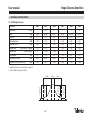
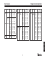
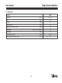
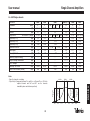
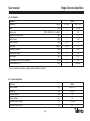
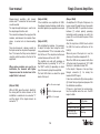
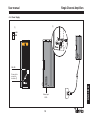
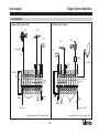
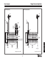
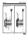
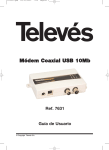
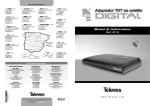
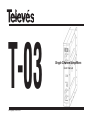
T-03
© Copyright, Televés S.A.
Single Channel Amplifiers
User manual
User manual
Single Channel Amplifiers
1.- REFERENCES DESCRIPTION
Accessories:
Ref. 5081 .... Low gain BI amplifier
Ref. 5083 .... Low gain BIII amplifier
Ref. 5087 .... Mid Band amplifier
Ref. 4061 .... Load“F” 75 ohm
Ref. 5088 .... Upper Band amplifier
Ref. 5073 .... Face plate
Ref. 5089 .... Hyper Band amplifier
Ref. 5074 .... Link “F” connectors
Ref. 5099 .... DAB amplifier
Ref. 5071 .... Wall mount (10 mod. + P.S.U.)
Ref. 5082 .... FM Amplifier T03
Ref. 5239 .... Wall mount (12 mód. + P.S.U.)
Ref. 5084 .... Low gain UHF amplifier
Ref. 5072 .... Universal cabinet (10 mod. + P.S.U.)
Ref. 5094 .... High gain UHF amplifier
Ref. 5069 .... Universal cabinet (14 mod. + P.S.U.)
Ref. 5097 .... A.G.C. UHF amplifier
Ref. 5235 .... Universal cabinet (22 mod. + P.S.U.)
Ref. 5098 .... UHF amplifier high selectivity
Ref. 5301 .... 19” wall/sub-rack
Ref. 5086 .... UHF DTT amplifier
Ref. 8250 .... 19” sub-rack
Ref. 5085 .... UHF DTT amplifier with coupler
Ref. 5302 .... MATV headend cabinet
Ref. 5080 .... IF Amplifier (950 - 2150 MHz)
Ref. 5498 .... Power supply
(230 V ± 15 % - 50/60 Hz)
ENGLISH
(24 V - 2,5 A)
Refs. 5072, 5069, 5235
Ref. 5301
Ref. 8250
45
Ref. 5302
User manual
Single Channel Amplifiers
2.- TECHNICAL SPECIFICATIONS
2.1.- VHF Single-channels
Reference
Bandwidth
(MHz)
Gain
(dB)
5081
5083
5099
5087
5088
7
7 / 16 (1)
37
7
7
5089
8
50 ±2
50 ±2
45 ±3
58 ±2
58 ±2
58 ±2
Flatness
(dB)
<1
<1
<3
<1
<1
<1
Gain adjustment
(dB)
> 35
> 35
> 35
> 35
> 35
> 35
Rejection (n ±2)
(dB)
> 40
> 30
> 20
> 30
> 25
> 30
Output level
(EN 50083-5) (dBµV)
123
123
--
125
124
125
Output level
(DAB) (dBµV)
--
112 (2)
114 (2)
--
--
--
Noise figure
(dB)
<9
<9
<9
<9
<9
<9
Consump. at 24Vcc
(mA)
65 ±5
65 ±5
90 ±5
90 ±5
90 ±5
90 ±5
Preamp. max. current (24Vcc)
(mA)
100
100
100
100
100
100
1.- Adjust CH13 (refer to channels table on page 21)
2.- Fordi= 50 dB (2 channels at 4 MHz)
n-3
14 MHz
n-2
46
Rejection
n +2
n-1
n
n+1
n+2
Rejection
n +3
7 MHz
Rejection
n -2
Rejection
n -3
14 MHz
n+3
User manual
Single Channel Amplifiers
Band
Chan.
Channel
Freq. (MHz)
Ref.
Band
Chan.
Channel
Freq. (MHz)
Ref.
Band
Chan.
Channel
Freq. (MHz)
5081
BI
2
3
4
47 ... 54
54 ... 61
61 ... 68
5087
BS
Mid
BS
Hyper
L1
L2
L3
68 ... 75
75 ... 82
82 ... 89
B III
C5
C6
C7
C8
C9
C10
C11
C12
C13
174 ... 181
181 ... 188
188 ... 195
195 ... 202
202 ... 209
209 ... 216
216 ... 223
223 ... 230
216 ... 232 (DAB-UK)
104 ... 111
111 ... 118
118 ... 125
125 ... 132
132 ... 139
139 ... 146
146 ... 153
153 ... 160
160 ... 167
167 ... 174
5089
Sub
Band
S1
S2
S3
S4
S5
S6
S7
S8
S9
S10
5088
BS
Upper
DAB
195 ... 232
S11
S12
S13
S14
S15
S16
S17
S18
S19
S20
230 ... 237
237 ... 244
244 ... 251
251 ... 258
258 ... 265
265 ... 272
272 ... 279
279 ... 286
286 ... 293
293 ... 300
S21
S22
S23
S24
S25
S26
S27
S28
S29
S30
S31
S32
S33
S34
S35
S36
S37
S38
S39
S40
S41
302 ... 310
310 ... 318
318 ... 326
326 ... 334
334 ... 342
342 ... 350
350 ... 358
358 ... 366
366 ... 374
374 ... 382
382 ... 390
390 ... 398
398 ... 406
406 ... 414
414 ... 422
422 ... 430
430 ... 438
438 ... 446
446 ... 454
454 ... 462
462 ... 470
5083
5099
ENGLISH
Ref.
47
User manual
Single Channel Amplifiers
2.2.- FM Amplifier
Reference
5082
Bandwidth
(MHz)
87,5 - 108
Gain
(dB)
Flatness
(dB)
<3
Gain adjustment
(dB)
> 35
Rejection77 MHz and 120 MHz
35 ±3
(dB)
> 30
Output level
(UNE - 523-79) (dBµV)
114
Noise figure
(dB)
<9
Consumption at 24Vcc
(mA)
65 ±5
Preamp. maximum current (24Vcc)
(mA)
100
48
User manual
Single Channel Amplifiers
2.3.- UHF Single-channels
5086
24
32
40
50 ±3
<3
111 109 108 108
>3
> 15
> 30
> 20
> 15
<9
> 30
70 ±5
100
16
Notes:
- Especify channels on ordering.
- Rejection (n±1): measured between PV N and PA N-1 or PA N and PV N+1, if N is the
adjusted channel and N+1 and N-1 are the channels
inmediately above and below respectively.
16 MHz
8 MHz
5098
6
52 ±3
<2
> 121
> 15
> 50
< 11
> 30
90 ±5
100
n-2
n-1
n
5097
8
57 ±3
>1
A:125 / D:118
>3
> 25
> 50
<9
20
30
90 ±5
100
16 MHz
Rejection
n-2
Rejection
n-3
n-3
49
5085 (DTT)
32
57 ±2
<3
> 106
> 22
<9
> 30
> 15
< 1,2
90 ±5
100
n+1
n+2
n+3
ENGLISH
5094
8
57 ±3
<1
> 125
>3
> 25
> 50
<9
> 30
90 ±5
100
Rejection
n+3
5084
8
48 ±2
<1
> 120
>3
> 25
> 50
<9
> 30
70 ±5
100
Rejection
n+2
Reference
Bandwidth
(MHz)
Gain
(dB)
Flatness
(dB)
Output level
EN 50083-5 (dBµV)
Rejection (n ± 1)
(dB)
Rejection (n ± 2)
(dB)
Rejection (n ± 3)
(dB)
Rejection Vc ch 65
(dB)
Noise figure
(dB)
Gain adjustment
(dB)
Directivity (output mixing)
(dB)
Output through attenuation
(dB)
A.G.C. margin
(dB)
Consump. at 24Vdc
(mA)
Pream. max. current (24Vdc)
(mA)
User manual
Single Channel Amplifiers
2.4.- IF Amplifier
Reference
5080
Bandwidth
(MHz)
47 - 862
950 - 2150
(dB)
---
35 - 50
(DIN V VDE 0855/12) (dBµV)
---
124
Gain
Output level
Rejection between inputs
(dB)
---
> 10
Return losses
(dB)
---
> 10
(dB)
< 1.5
---
(dBµV)
> 100
---
---
> 20
Insertion losses
Input level
Attenuation margin
(dB)
Equalisation margin
(dB)
---
> 12
Noise figure
(dB)
---
12.5
Consumption at 24Vcc (just amplifier)*
(mA)
---
130
LNB current (input 2)
(mA)
---
400 max.
* For the installation calculation, add the predicted LNB consumption
2.5.- Power Supply Unit
Reference
5498
Mains voltage
(V~)
230 ± 15 %
Frequency
(Hz)
50 / 60
Maximum power
(W)
70
Output voltage
(V=)
24
Maximum output current
(A)
2.5 (24V)
Maximum output power
(W)
60
50
User manual
Single Channel Amplifiers
3 .- MOUNTING
3.1.- Wall Mounting
Single channel amplifiers
Signal input
5498
CLAC!
5071
5239
2
4061
5074
Signal output
51
ENGLISH
PWR
1
User manual
Single Channel Amplifiers
3.2.- 19” Rack Mounting
CLAC!
8250
PWR
5301
5073
52
User manual
Single Channel Amplifiers
4. - DESCRIPTION OF ELEMENTS
4.1.- Single-channels
1
1
1
2
5
5
7
6
2
3
7
7
9
3
6
8
10
4
23464
ref. 5085
1.- RF input loop (+ 24Vdc)
2.- RF output loop
3.- Preamplifier power switch (On/Off)
4.- Switch to select the analogue or digital
channels (only ref. 5097)
5.- Output level adjustment
6.- Mains connector
7.- ON LED
1.- RF input loop (+ 24Vdc)
2.- Input for the mixing of other RF channels
3.- RF output
4.- Preamplifier power switch (On/Off)
5.- ON LED
6.- Attenuator
7.- Mains connector
53
ref. 5080
1.- IF Input
2.- IF input + Vlnb/22KHz
3.- MATV input
4.- IF output + MATV
5.- Equaliser
6.- 0/22 KHz tone
7.- Selection of LNB current
(Disabled / vertical (12V) / horizontal (18V))
8.- ON LED
9.- Attenuator
10.- Powering connector
ENGLISH
2
6
4
5
PWR
3
4
User manual
Single-channel amplifiers with diecast
chassis and “F” connectors that can be rack
or wall mounted.
The loop-through technique is used to mix
the output signal from the units.
The connection between the supply and the
modules, and between the modules themselves, is carried out via interconnecting
links.
They also dispose of a bypass current via
the input connectors to power the preamplifiers. This means that they can be disabled
using the switch located on the front of the
equipment.
When various modules are used in an
installation, the channels with higher
frequencies must be located near to the
output that is to be used.
(Only ref. 5085)
With ref. 5085, given the output directivity,
the mixing with the other channels in the
installation is carried out via connector “2”
and the output of the single channel, via
connector “3”.
Single Channel Amplifiers
(Only ref. 5098)
If the installation uses amplifiers ref. 5098,
the adjacent channel modules should not be
mounted together (see application example
6).
(Only ref. 5097)
After installing the modules, it is necessary
to adjust the output level using the multiturn potentiometre "5" that is located on the
front of the unit. The output level will remain
constant because of the units' AGC.
The amplifier can work with analogue or
digital channels, by selecting "A" or "D" on
the "AGC" switch (4) depending on which
type of channel is going to be amplified.
The front LED informs us about the signal
levels at the input.
RED => Excessive signal
GREEN => Optimum signal
(Only ref. 5080)
An amplifier with 2 IF inputs. It disposes of a
bypass current through the input connector
(2) to feed the LNB. It is possible to choose
between (7) vertical polarity powering,
horizontal polarity powering or switch the
power off, so as to be able to power it from
the outside.
Also, this input has a 22KHz tone to control
the LNB, that can be switched on at the
front (6).
When only one of the inputs is in use, the
other input should be charged with 75 .
When the LNB can be powered with either
of the two levels (for example ref. 7477, LNB
Quatro), is is advisable to select 18V.
In the output, it disposes of an input loop
through connector (3) for mixing the
headend’s MATV signal.
It also has an attenuator (9) and an equaliser
(5) to treat the input signal and prepare it for
the distribution conditions.
If there is a short-circuit or overconsumption, the amplifier warns the user - the LED
begins to blink.
AMBER => Poor signal
VLNB OFF
VLNB ON (13 or 18V)
Short-circuit or
overconsumption
54
LED colour
Green
Amber
Blinking
User manual
Single Channel Amplifiers
4.2.- Power Supply
(1)
(1)
PWR
+ 24V
GND
ON LED
Mains input
230V~
55
ENGLISH
Connector to
power the
modules (1)
User manual
Single Channel Amplifiers
7.- APPLICATIONS
1.- General (FM + VHF + UHF)
2.- With IF single channel
UHF
VHF
FM
UHF
VHF
Preamplifier
FM
+24V
Preamp.
13V +22KHz
75 ohm
4061
SW. ON
C58
C50
5498
C46
C35
UHF
C30
C21
C10
C4
VHF
DAB
FM
FM
5082
75 ohm
4061
C4
C10
C25
C30
C36
5498
C58
FI
Sw. “22KHz”
Sw. “V”
5080
5082
RF output
C50
VHF
DAB
UHF
IF output + MATV
Preamplifier switches OFF, except in Ch58
Preamplifier switches OFF, except in Ch58
56
User manual
Single Channel Amplifiers
3.- DTT with Ch 65
4.- DTT without Ch 65
UHF
UHF
FM
FM
5254
Ch65
4093
Ch66
4093
75 ohm
4061
75 ohm
4061
FM
C22
C25
C28
C32
C35
C46
C50
C65
DTT
FM
5085
C22
C25
C28
C32
C35
C46
C50
C58
DTT
5086
5498
5082
5084
5094
5097
5498
5082
RF output
5084
5094
5097
RF output
Preamplifier switches OFF
Preamplifier switches OFF
57
ENGLISH
RF channel mixing
User manual
Single Channel Amplifiers
5.- With adjacent channels (Ch56, Ch57, Ch58)
6.- Only with adjacent channels (Ch57, Ch58, Ch59, ... Ch64)
( )
* Installations with AGC
UHF
UHF
FM
FM
5098
75 ohm
4061
FM
C28
C31
75 ohm
4061
C34
C57
C48
C56
C45
C58
FM
5498
5498
5082
5084
5094
5097 (*)
RF output
C57
C59
C61
C63
C58
C60
C62
C64
5098
RF output
Preamplifier switches OFF
Preamplifier switches OFF
58
Garantía
Televés S.A. ofrece una garantía de dos años calculados a partir de la fecha de compra para
los países de la UE. En los países no miembros de la UE se aplica la garantía legal que está
en vigor en el momento de la venta. Conserve la factura de compra para determinar esta
fecha.
Durante el período de garantía, Televés S.A. se hace cargo de los fallos producidos por
defecto del material o de fabricación. Televés S.A. cumple la garantía reparando o sustituyendo el equipo defectuoso.
No están incluidos en la garantía los daños provocados por uso indebido, desgaste, manipulación por terceros, catástrofes o cualquier causa ajena al control de Televés S.A.
Garantia
Televés S.A. oferece uma garantia de dois anos calculados a partir da data de compra para
os países da UE. Nos países não membros da UE aplica-se a garantia legal que está em
vigor no momento da venda. Conserve a factura de compra para poder comprovar a data.
Durante o período de garantia, Televés S.A. assume as falhas do produto ocorridas por
defeito do material ou de fabrico. Televés S.A. cumpre a garantia reparando ou substituindo
o equipamento defeituoso.
Não estão incluídos na garantia os danos provocados pela utilização indevida, desgaste,
manipulação por terceiros, catástrofes ou qualquer causa alheia ao controlo de Televés S.A.
Garantie
Televés S.A. offre une garantie de deux ans calculée à partir de la date d’achat pour les pays
de l’U.E. Pour les pays non membres de l’U.E., la garantie appliquée sera celle en vigueur du
point de vue légal au moment de la vente. Conservez votre facture d’achat afin d’attester de
cette date.
Pendant la période de garantie, Televés S.A. prend en charge les avaries dues à un défaut
du produit ou de fabrication. Televés assume cette garantie en réparant ou en échangeant
l’appareil défectueux.
Ne sont pas couverts par la garantie les dommages provoqués par une utilisation incorrecte,
usure normale d’utilisation, manipulation par des tiers, catastrophes ou toute cause hors du
contrôle de Televés S.A.
Guarantee
Televés S.A. offers a two year guarantee, beginning from the date of purchase for countries
in the EU. For countries that are not part of the EU, the legal guarantee that is in force at the
time of purchase is applied. Keep the purchase invoice to determine this date.
During the guarantee period, Televés S.A. complies with the guarantee by repairing or
substituting the faulty equipment.
The harm produced by improper usage, wear and tear, manipulation by a third party,
catastrophes or any other cause beyond the control of Televés S.A. is not included in the
guarantee.
SUCURSALES
GIJON
A CORUÑA
BILBAO
CANTABRIA
LUGO
SANTIAGO
VIGO
GUIPUZCOA
ALAVA
OURENSE
LEON
ZAMORA N
PALENCIA
NAVARRA
BARCELONA
SORIA
ZARAGOZA
ZAMORA
SEGOVIA
SALAMANCA
GUADALAJARA
AVILA
OPORTO
CACERES
TOLEDO
CASTELLON
CUENCA
CIUDAD REAL
VALENCIA
ALICANTE
JAEN
PALMA DE
MALLORCA
ALBACETE
BADAJOZ
CORDOBA
TARRAGONA
TERUEL
MADRID
LISBOA
GIRONA
HUESCA
BURGOS
LA RIOJA
VALLADOLID
MURCIA
BALEARES
BARCELONA C.P. 08940
C/ Sant Ferrán, 27
Cornellá - Barcelona
Telfs. 93 377 08 62 / 93 474 29 50
Fax
93 474 50 06
E-mail [email protected]
BILBAO C.P. 48150
Iberre kalea, módulo 16,
pabellón 15-B
Sangroniz-Sondika
Tfnos. 94 471 12 02 / 94 471 24 78
Fax
94 471 14 93
[email protected]
GRANADA
HUELVA
SEVILLA
ALMERIA
MALAGA
CADIZ
CANARIAS
SUCURSALES
TENERIFE
LAS PALMAS C.P. 35006
Gral. Mas de Gaminde 26.
Tfnos. 928 23 11 22 / 928 23 12 42
Fax
928 23 13 66
[email protected]
MADRID C.P. 28005
Paseo de los Pontones 11.
Tfnos. 91 474 52 21 / 91 474 52 22
Fax
91 474 54 21
[email protected]
MURCIA C.P. 30010
Polígono Conver
C/ Rio Pliego 22
Tfnos. 968 26 31 44 / 968 26 31 77
Fax
968 25 25 76
[email protected]
SEVILLA C.P. 41008
Pol. Ind. Store - C/ A-6. Nave 5
Tfnos. 95 443 64 50 / 95 443 58 00
Fax
95 443 96 93
[email protected]
VALENCIA C.P. 46020
Plaza Jordi San Jordi s/n
Tfnos. 96 337 12 01 / 96 337 12 72
Fax
96 337 06 98
[email protected]
VIGO C.P. 36204
Escultor Gregorio Fernández, 5
Tfnos. 986 42 33 87 / 986 42 40 44
Fax
986 42 37 94
[email protected]
TENERIFE C.P. 38108
Avda. El Paso, 25
Los Majuelos - La Laguna.
Tfnos. 922 31 13 14 / 922 31 13 16
Fax
922 31 13 33
[email protected]
DELEGACIONES
CEUTA
LAS PALMAS
A CORUÑA C.P. 15011
Gregorio Hernández 8.
Tfnos. 981 27 47 31 / 981 27 22 10
Fax
981 27 16 11
[email protected]
GIJON C.P. 33210
C/Japón, 14
Tfnos : 985 15 25 50 / 985 15 29 67
Fax : 985 14 63 89
[email protected]
MELILLA
FABRICAS
DELEGACIONES
ALMERIA C.P. 04008
Campogrís 9.
Tfno. 950 23 14 43
Fax
950 23 14 43
[email protected]
BURGOS C.P.09188
C/Real, s/n,
San Adrián de Juarros
Tfno. 947 56 04 58 / 670 73 75 86
CACERES/ BADAJOZ
C.P. 06010
C/Jacobo Rodríguez
Pereira, nº11-Oficina
Tfno. 924 20 74 83 / 670 70 21 93
Fax.
924 20 01 15
[email protected]
Rúa B. de Conxo, 17 - 15706 SANTIAGO DE COMPOSTELA
Tel. 981 52 22 00 Fax 981 52 22 62
GIRONA C.P. 17190 (Salt)
Ramón Sambola. 9º Ent. 1ª.
Tfno. 972 23 25 43 / 607 23 88 40
[email protected]
GRANADA
Tfno. 958 13 78 29
Móvil: 609 62 70 96
[email protected]
JAEN C.P. 23007
Hermanos Pinzón, 8-bajo
Tfnos. 953 29 50 40 / 953 29 52 21
639 98 44 89
Fax
953 29 52 10
[email protected]
LA RIOJA C.P. 26004
San Prudencio 19. bajo
Tfno. 941 23 35 24
Fax
941 25 50 78
[email protected]
MALAGA C.P.29004
Pol. Santa Barbara - C/ Fidias 13.
Tfno. 95 223 98 81
Fax
95 217 37 30
[email protected]
P. DE MALLORCA C.P. 07007
Ferrer de Pallares 45. bajo D.
Tfno. 971 24 70 02
Fax
971 24 53 42
[email protected]
MELILLA C.P.52006
Paseo Marítimo Mir Berlanga, 17
Edif. Antares, C, 4ºB
Tfno. 600 45 35 13
Fax
600 43 35 14
[email protected]
SALAMANCA
ZAMORA
VALLADOLID C.P. 47008
C/ Arrecife 12.
Tfno. 983 22 36 66
Fax
983 22 36 66
[email protected]
NAVARRA C.P. (Pamplona) 31007
Avda. Sancho el Fuerte 9.
Tfno. 948 27 35 10
Fax
948 17 41 49
[email protected]
HUESCA
ZARAGOZA C.P. 50002
C/ Monasterio de Alahón 1-3.
Tfno. 976 41 12 73
Fax
976 59 86 86
[email protected]
[email protected]
www.televes.com
TELEVES ELECTRONICA PORTUGUESA
MAIA - OPORTO
Via . Dr Francisco Sa Carneiro. Lote 17.
ZONA Ind. MAIA 1. Sector-X MAIA.
C.P. 4470 BARCA
Tel.
351 22 9418313
Fax
351 22 9488719 / 9416180
[email protected]
LISBOA
C.P. 1000 Rua Augusto Gil 21-A.
Tel.
351 21 7932537
Fax
351 21 7932418
[email protected]
TELEVES UNITED KINGDOM LTD
Unit 11 Hill Street, Industrial State
CWMBRAN, GWENT NP44 7PG. (United Kingdom)
Tel.
44 01 633 87 58 21
Fax
44 01 633 86 63 11
[email protected]
TELEVES FRANCE S.A.R.L.
35 Av St Germain des Noyers
77400 St Thibault des Vignes (France)
Tel. 01 60 35 92 10
Fax 01 60 35 90 40
[email protected]
TELEVES MIDDLE EAST FZE
P.O. Box 17199
JEBEL ALI FREE ZONE DUBAI,
UNITED ARAB EMIRATES
Tel.
9714 88 343 44
Fax. 9714 88 346 44
[email protected]
103554/0 - 04-01