1
®
ANSI® Programmer’s Reference Manual
ANSI® Printers
Programmer’s Reference Manual
®
Trademark Acknowledgements
Printronix, Inc. makes no representations or warranties of any kind regarding
this material, including, but not limited to, implied warranties of
merchantability and fitness for a particular purpose. Printronix, Inc. shall not
be held responsible for errors contained herein or any omissions from this
material or for any damages, whether direct, indirect, incidental or
consequential, in connection with the furnishing, distribution, performance or
use of this material. The information in this manual is subject to change
without notice.
This document contains proprietary information protected by copyright. No
part of this document may be reproduced, copied, translated or incorporated
in any other material in any form or by any means, whether manual, graphic,
electronic, mechanical or otherwise, without the prior written consent of
Printronix, Inc.
Copyright © 1998, 2012 Printronix, Inc.
All rights reserved.
Trademark Acknowledgements
ANSI is a registered trademark of American National Standards Institute, Inc.
Centronics is a registered trademark of Genicom Corporation.
Dataproducts is a registered trademark of Dataproducts Corporation.
Epson is a registered trademark of Seiko Epson Corporation.
IBM and Proprinter are registered trademarks and PC-DOS is a trademark of
International Business Machines Corporation.
MS-DOS is a registered trademark of Microsoft Corporation.
Printronix, IGP, PGL, LinePrinter Plus, and PSA are registered trademarks of
Printronix, Inc.
QMS is a registered trademark and Code V is a trademark of Quality Micro
Systems, Inc.
Table of Contents
1 Introduction........................................................... 9
About this Manual .................................................................................. 9
Audience ......................................................................................... 9
Warnings and Special Information .................................................. 9
Related Product Information .................................................................. 9
Software Features ................................................................................. 9
Installing Printer Emulations ................................................................ 10
Downloading Software through the Serial or Parallel Port ............ 11
Downloading Software through the Network Interface Card (NIC) 14
Downloading Optional Font Files to Flash Memory....................... 16
Flash Memory Message Guide ..................................................... 19
2 ANSI Emulation .................................................. 23
Overview.............................................................................................. 23
ANSI Emulation Default Settings................................................... 23
Configuring the ANSI Emulation .......................................................... 26
Control Codes ............................................................................... 26
Format for Control Code Descriptions........................................... 28
Control Codes Index ..................................................................... 30
Character Sets, International ........................................................ 31
Expanded Mode ............................................................................ 33
Forms Length, Top Margin, Bottom Margin................................... 34
Graphic Rendition ......................................................................... 35
Horizontal Position Absolute ......................................................... 36
Horizontal Position Backward........................................................ 36
Horizontal Positive Relative........................................................... 36
Horizontal/Vertical Position Absolute ............................................ 37
Line Spacing ................................................................................. 37
Margins, Left and Right ................................................................. 38
Private Mode, Disable ................................................................... 39
Private Mode, Enable .................................................................... 39
Proportional Print Mode ................................................................ 39
Resetting ....................................................................................... 40
Subscript ....................................................................................... 41
Superscript .................................................................................... 41
Tab, Clear ..................................................................................... 41
Table of Contents
Tab Set, Multiple Horizontal .......................................................... 42
Terminate Loading of Data............................................................ 43
Vertical Position Absolute ............................................................. 43
Vertical Position Backward............................................................ 43
Vertical Position Relative .............................................................. 43
Vertical Tab Set............................................................................. 44
Graphics .............................................................................................. 45
Dot Patterns And Densities ........................................................... 45
Horizontal Format.......................................................................... 47
Vertical Format .............................................................................. 47
Other Graphics Considerations ..................................................... 48
Dot Graphics ................................................................................. 48
Repeat Graphics Character .......................................................... 48
Select Graphics Mode................................................................... 49
Bar Codes............................................................................................ 50
Entering and Exiting Bar Codes .................................................... 50
Setting Bar Code Parameters ....................................................... 50
Human Readable Line (HRL) ........................................................ 54
Spacing between Bar Codes......................................................... 54
Bar Code Readers ........................................................................ 55
Test Program ................................................................................ 56
Vertical Bar Codes ........................................................................ 56
Oversize Character Font Option .......................................................... 58
Entering and Exiting Oversize....................................................... 58
Selecting Size ............................................................................... 59
3 Vertical Page Formatting .................................... 61
Overview.............................................................................................. 61
Planning a Vertical Page Format ......................................................... 61
VFU Characteristics ...................................................................... 62
Proprinter and Epson Vertical Tab Table............................................. 62
Executing Vertical Tabs ................................................................ 62
Vertical Tab Positions ................................................................... 62
P-Series EVFU .................................................................................... 64
Start Load Code - 1E or 6E Hex ................................................... 64
Channel Assignment ..................................................................... 64
End Load - 1F or 6F Hex............................................................... 65
Using the EVFU ............................................................................ 65
Clearing the EVFU Memory .......................................................... 67
Relative Line Slewing.................................................................... 67
Table of Contents
ANSI EVFU.......................................................................................... 68
Loading the Table ......................................................................... 69
The Default.................................................................................... 71
The Skip to Channel Command .................................................... 72
Downloading the EVFU (Using The PI Line) ................................. 73
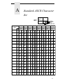
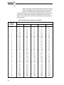
A Standard ASCII Character Set ........................... 77
B Conversion Tables ............................................. 79
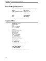
C Contact Information............................................ 87
Printronix Customer Support Center.................................................... 87
Printronix Supplies Department ........................................................... 88
Corporate Offices................................................................................. 88
D Glossary............................................................. 89
Table of Contents
1
Introduction
About this Manual
This manual lists the ANSI® commands and explains how to configure the
printer when this emulation is loaded in your printer.
Audience
This book assumes you are an experienced programmer and are familiar with
the ANSI emulation.
Warnings and Special Information
Read and comply with all information highlighted under special headings:
WARNING
CAUTION
IMPORTANT
Conditions that could harm you as well as damage the equipment.
Conditions that could damage the printer or related equipment.
Information vital to proper operation of the printer.
NOTE: Information affecting printer operation.
Related Product Information
The User's Manual describes the keys on the control panel and provides
quick reference information on daily printer operations such as loading paper
and replacing ribbons. This book also provides configuration instructions and
descriptions and troubleshooting guidelines.
Software Features
The ANSI emulation software provides the following features:
•
Graphics and a selection of print densities. You can enable graphics
mode and specify a density mode (dots per inch).
•
Print Attributes. Characters can be bold, italic, double high, double wide,
etc.
•
Page Formatting. American National Standards Institute (ANSI)
commands allow you to set line spacing, page length, and vertical forms
control.
9
Chapter
1
Installing Printer Emulations
•
Font Typefaces. Also referred to as print modes. The five typefaces
include Near Letter Quality (NLQ), Data Processing (DP), High Speed
(HS), OCR A, and OCR B.
•
Character Sets. Fifty-one character sets are available. You can print the
character sets in the different print modes.
•
Bar codes. Several bar codes are available: Code 3 of 9, IATA 2 of 5,
Interleaved 2 of 5, UPC A, EAN 8, EAN 13, UCC 128, and Codabar.
•
•
Expanded/Oversize print modes.
Forms Positioning. Several commands are available to set print position
(relative or absolute).
Installing Printer Emulations
Printer emulation software is stored in flash memory. Flash memory is
contained in single in-line memory modules (SIMMs) located on the controller
board. Printer emulation and operating system software are loaded into flash
memory at the factory, but you will install software in some situations:
•
•
•
A printer software upgrade is installed
The printer controller board has been replaced
The flash memory SIMM has been replaced
Emulation and operating system software are stored on a CD. You will copy
the appropriate file to your computer’s hard disk, then download that file to the
printer. You can load software through the serial, parallel, or Ethernet NIC
port of the printer.
NOTE: If the NIC is installed, you must download the code through the NIC
port using ftp.
NOTE: Each printer type, line matrix, laser, and thermal, has its own CD with
the specific file types for that printer. Be sure to use the appropriate
CD for your printer type when downloading software.
IMPORTANT
10
When downloading emulation and operating system software to the
printer, all other optional font files, customer-supplied logos, setup files,
and TIFF files will be erased. You will then need to reload those files.
Before starting a download procedure, be sure that you have all the
necessary files on hand.
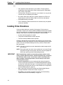
•
Serial or Parallel Port: If you are going to load memory through the
serial or parallel port of the printer, see “Downloading Software through
the Serial or Parallel Port” on page 11. The load commands are different,
depending on the printer port you use. These differences are explained in
the note following step 22., page 13.
•
NIC: If the printer has the NIC installed, see “Downloading Software
through the Network Interface Card (NIC)” on page 14.
•
Font Files: If you need to load optional font files, see “Downloading
Optional Font Files to Flash Memory” on page 16.
Downloading Software through the Serial or Parallel Port
Downloading Software through the Serial
or Parallel Port
1. Make a printout of all saved configurations. (Installing new software
erases all saved configurations. You will use the printouts to restore the
printer configurations.)
2. Set the printer power switch to O (Off).
3. If the printer is already connected to the serial or parallel port of an
IBM-compatible computer running the PC-DOS™ or MS-DOS operating
system, go to step 9. If not, go to step 4.
4. Unplug the AC power cord from the printer.
5. Disconnect all data input cables from the printer interfaces.
6. Connect a parallel data cable to the LPT1 port or a serial data cable to the
COM1 port of an IBM-compatible computer running the PC-DOS or
MS-DOS operating system.
NOTE: You can connect the cable to the LPT2 port if the LPT1 port is already
in use. The load commands are different if you use this port, as
described in the note after step 22.
7. Connect the data cable to the appropriate I/O port of the printer.
8. Plug the AC power cord into the printer.
9. On the printer control panel, press and hold down the ONLINE + PAPER
ADVANCE keys. Without releasing the keys, power the printer on.
Continue holding down the keys.
10. When you see “TESTING HARDWARE PLEASE WAIT” on the LCD,
release the keys.
11. Wait until you see “WAITING FOR PROGRAM DOWNLOAD” on the LCD
before proceeding. This can take up to 30 seconds to appear, depending
on the emulations and interfaces installed in the printer.
12. Press the ⇒ (NEXT) key. “SELECT DOWNLOAD
PORT=CENTRONICS” appears on the LCD.
NOTE: The default port is CENTRONICS; this is the standard load through
the parallel port. If you want to use the default, continue at step 14..
13. Press ⇒ (NEXT) again to cycle through the download ports available in
the printer:
RS232-9600 (RS-232 serial, 9600 baud)
RS232-19.2K (RS-232 serial, 19200 baud)
RS232-38.4K (RS-232 serial, 38400 baud)
RS232-115K (RS-232 serial, 115000 baud)
RS422-9600 (RS-422 serial, 9600 baud)
RS422-19.2 (RS-422 serial, 19200 baud)
RS422-38.4K (RS-422 serial, 38400 baud)
RS422-115K (RS-422 serial, 115000 baud)
DEBUG
14. When the printer download port you want to use displays on the LCD,
press the ENTER key. “WAITING DOWNLOAD / PORT = <your
selection>” appears on the display.
11
Chapter
1
Installing Printer Emulations
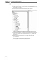
15. Using Windows Explorer, create a directory named download at the root
level of your C: hard drive.
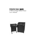
16. Insert the printer emulation software CD into your computer.
Figure 1. Navigating to the Appropriate Emulation File on the CD
17. Using Windows Explorer, navigate to the appropriate file on the CD based
on the printer model number and desired emulation, e.g., T5000IGP.
(See Figure 1.)
18. Make note of the file name, which is a six digit number plus .exe
e.g., 123456.exe.
This is the file you will download into the printer.
12
Downloading Software through the Serial or Parallel Port
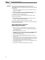
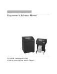
Figure 2. Copying the Emulation File to the Download Directory
19. Copy the file to the download directory.
NOTE: You may need to hold Ctrl to make sure a + appears to the right of
the pointer. (See Figure 2.)
20. Start a command prompt session. (The Start Menu icon is usually labeled
MS-DOS Prompt or Command Prompt.)
21. At the command prompt type:
C:<Enter>
cd \download<Enter>
22. At the command prompt on the computer type:
filename.exe -pb<Enter>
where filename.exe is the file name you noted in step 18. This command
decompresses the file on the hard drive and copies it as a binary file into
the flash memory on the printer controller board.
NOTE: If you are loading the file using the LPT2 port on the computer, enter
the following command:
filename.exe -pb2 <Enter>
The 9600 baud rate is the only selection older versions of MS-DOS
can use. The baud rate information entered in the following
commands must match the selection you made in step 13.
If you are loading the file through the printer serial port, enter the
following commands:
mode COM1:9600,N,8,1,P<Enter>
filename.exe -pbc1<Enter>
13
Chapter
1
CAUTION
Installing Printer Emulations
Do not interrupt the downloading process once it has started.
Interrupting a download will damage the flash memory on the controller
board and NIC.
While the file is copied into memory, the printer LCD informs you of the
load process and status.
23. When the new program has successfully loaded into memory and the
printer has reset itself, set the printer power switch to O (Off).
24. Unplug the AC power cord from the printer.
25. Remove the CD from the host computer and store it with the printer.
26. Power off the computer.
27. If you had to install a data cable to the computer and printer in step 6,
disconnect it from the computer and printer.
28. If required, reconnect the data input cable(s) to the printer.
Using the configuration printout(s) you made in step 1, reconfigure the printer
and reload any optional font files.
Downloading Software through the
Network Interface Card (NIC)
1. Make a printout of all saved configurations. (Installing new software
erases all saved configurations. You will use the printouts to restore the
printer configurations.)
2. Set the printer power switch to O (Off).
3. On the printer control panel, press and hold down the ONLINE + PAPER
ADVANCE keys. Without releasing the keys, power the printer on.
Continue holding the keys down.
4. When you see “TESTING HARDWARE PLEASE WAIT” on the LCD,
release the keys.
5. Wait until you see “WAITING FOR PROGRAM DOWNLOAD” on the LCD
before proceeding. This can take up to 30 seconds to appear, depending
on the emulations and interfaces installed in the printer.
6. Using Windows Explorer, create a directory named download at the root
level of your C: hard drive.
7. Insert the printer emulation software CD into your computer.
14
Downloading Software through the Network Interface Card (NIC)
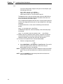
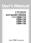
Figure 3. Navigating to the Appropriate Emulation File on the CD
8. Using Windows Explorer, navigate to the appropriate file on the CD (using
the Unzipped directory) based on the printer model number and desired
emulation, e.g., UnzippedT5000IGP. (See Figure 3.)
IMPORTANT
You must use the Unzipped directory, since this contains the
uncompressed files necessary for NIC download.
9. Make note of the file name, which is a six digit number plus .prg
e.g., 123456.prg.
This is the file you will download into the NIC.
10. Copy the file to the download directory.
11. Start a command prompt session. (The Start Menu icon is usually labeled
MS-DOS Prompt or Command Prompt.)
12. At the command prompt type:
C:<Enter>
cd \download<Enter>
13. Start the FTP protocol by typing:
ftp xxx.xxx.xxx.xxx<Enter>
(where xxx.xxx.xxx.xxx represents the IP Address of the printer.)
14. Log in to the printer by typing:
root<Enter>
You are given a password prompt.
15
Chapter
1
Installing Printer Emulations
NOTE: The default is no password. If the FTP program requires a password,
contact your system administrator.
15. At the password prompt, press <Enter>.
16. Once logged in, type the following sequence at the command prompt to
download the filename.prg file to the printer:
cd dest<Enter>
cd d1prn<Enter>
bin<Enter>
put filename.prg<Enter>
(where filename.prg is the file name you noted in step 9.)
CAUTION
Do not interrupt the downloading process once it has started.
Interrupting a download will damage the flash memory on the controller
board and NIC.
17. As the file downloads, the FTP program shows the progress as a
percentage. Once the download is complete, exit out of the FTP program
by typing:
quit<Enter>
18. When the new program has successfully loaded into flash memory and
the printer has reset itself, set the printer power switch to O (off).
19. Unplug the AC power cord from the printer.
20. Remove the CD from the host computer and store it with the printer.
21. Using the configuration printout(s), reconfigure the printer and reload any
optional font files.
Downloading Optional Font Files to Flash Memory
Optional font files are stored on a 3.5 inch floppy diskette that contains file
names comprised of a part number with a .dwn extension. You will insert the
diskette in your IBM-compatible computer and use either the parallel or serial
port to download the desired font file(s) to the printer’s flash memory.
1. Set the printer power switch to O (off).
2. Connect a parallel data cable to the LPT1 port or a serial cable to the
COM1 port of an IBM-compatible computer running the PC-DOS or
MS-DOS operating system.
NOTE: You can connect the cable to the LPT2 port on the computer if the
LPT1 port is already in use. The load commands are different if you
use this port, as described in the notes after step 16.
3. Verify that the data cable is connected to the appropriate I/O port on the
printer and to the host computer.
4. Power on the computer and allow it to boot up.
5. On the printer control panel, press and hold down the ONLINE + PAPER
ADVANCE keys while powering the printer on. Continue holding the keys
down.
6. When you see “TESTING HARDWARE PLEASE WAIT” on the LCD,
release the keys.
16
Downloading Optional Font Files to Flash Memory
7. Wait until you see “WAITING FOR PROGRAM DOWNLOAD” on the LCD
before proceeding. This can take up to 30 seconds to appear, depending
on the emulations and interfaces installed in the printer.
NOTE: The printer default port is CENTRONICS; if you want to use this port,
continue to step 16.
8. Press the ⇒ (NEXT) key; “SELECT DOWNLOAD PORT =
CENTRONICS” appears on the LCD.
9. Press the ⇒ (NEXT) key again to cycle through the download ports
available in the printer:
RS232-9600 (RS-232 serial, 9600 baud)
RS232-9600 (RS-232 serial, 19200 baud)
RS232-9600 (RS-232 serial, 38400 baud)
RS232-9600 (RS-232 serial, 115000 baud)
RS422-9600 (RS422 serial, 9600 baud)
RS422-9600 (RS422 serial, 19200 baud)
RS422-9600 (RS422 serial, 38400 baud)
RS422-9600 (RS422 serial, 115000 baud)
DEBUG
10. When the printer download port you want to use displays on the LCD,
press the ENTER key. “WAITING DOWNLOAD / PORT” = <your
selection> appears on the display.
11. Insert the optional font diskette into diskette drive A (or B) of the
computer.
12. Start a command prompt session. (The Start Menu icon is usually labeled
MS-DOS Prompt or Command Prompt.)
13. Make the diskette drive the active drive by typing:
A:<Enter> (if the diskette is in drive B, type B:<Enter>)
14. List the contents of the diskette at the command prompt by typing the
following:
dir<Enter>
You will see a directory listing containing files with a .dwn extension, e.g.,
94021.dwn, 94022.dwn, 94023.dwn.
15. Make note of the file name with the .dwn extension of each file you want
to download to the printer.
NOTE: The numeric portion of the file name will match the numbers of the
font typefaces listed in the PGL and VGL Programmer’s Reference
Manuals and provide you with a description and print sample of the
typeface.
16. At the command prompt type:
copy /b filename.dwn LPT1<Enter>
(where filename.dwn is file name you noted in step 15.)
NOTE: If you are loading the file using the LPT2 port on the computer, type
the following command:
copy /b filename.dwn LPT2<Enter>
(where filename.dwn is a file you noted in step 15.)
17
Chapter
1
Installing Printer Emulations
If you are loading the file using the serial port on the computer, type
the following commands:
mode COM1:9600,N,8,1,P<Enter>
copy /b filename.dwn COM1<Enter>
(where filename.dwn is a file you noted in step 15.)
The 9600 baud rate is the only selection older versions of MS-DOS can
use. The baud rate information entered in the above commands must
match the selection you made in step 9.
You can download the optional font files one at a time by entering one file
name per the copy command or you can copy multiple files in one copy
command.
To download one file at a time, enter the following at the command
prompt:
copy /b filename.dwn LPT1<Enter>
To download multiple files, enter the following at the command prompt,
for example:
copy /b filename1.dwn+filename2.dwn+...LPT1<Enter>
17. While the font file is copied into flash memory, the printer LCD informs
you of the load process and status. When the new file is successfully
loaded into memory, the printer will reset itself and go online.
18. To verify that the optional fonts have been downloaded:
a. Perform a configuration printout.
— OR —
b. Select MAINT/MISCFile SystemsView Files List. The new file
names will appear with the same part number file name you
downloaded, but with an .sf extension.
NOTE: The optional font typefaces cannot be selected via the printer control
panel. They can only be selected via a software command from the
host.
NOTE: Press the ONLINE key to place the printer online and return the
printer to normal operation.
18
Flash Memory Message Guide
Flash Memory Message Guide
Message
Explanation
Required Action
CLEARING PROGRAM
FROM FLASH
The program successfully
loaded into printer RAM and
the checksum matched. The
old program is now being
deleted from flash memory.
None
DIAGNOSTIC PASSED
The printer passed its
memory and hardware
initialization tests.
None
ERROR: DC PROGRAM
NOT VALID
Printer cannot find the data
controller program or the
validation checksum is
corrupt.
1. Download the program
again.
ERROR: DRAM AT
ADDRESS XXXXXXXX
The printer found a defective
memory location.
Replace the DRAM.
ERROR: EC PROGRAM
NOT VALID
Printer cannot find the engine
controller program or the
validation checksum is
corrupt.
1. Download the program
again.
ERROR: EC STOPPED AT
STATE XXXX
Hardware fault in the engine
controller.
Replace the CMX controller
board.
ERROR: FLASH DID NOT
PROGRAM
The printer could not find any
flash memory.
1. Download the program
again.
2. If the message occurs
again, replace the flash
memory.
2. If the message occurs
again, replace the flash
memory.
2. If the message occurs
again, replace the flash
memory.
ERROR: FLASH NOT
DETECTED
The printer could not find any
flash memory.
Install flash memory before
attempting to download this
program.
ERROR: NO DRAM
DETECTED
The printer could not find any
DRAM.
Check DRAM on CMX. If
present, reseat DRAM. If
missing, install DRAM.
ERROR: NVRAM FAILURE
The non-volatile memory has
failed.
Replace the CMX controller
board. (Do NOT attempt to
replace NVRAM.)
ERROR: PROGRAM NEEDS
MORE DRAM
The printer requires more
DRAM memory in order to run
the downloaded program.
Add DRAM or use a smaller
emulation program.
19
Chapter
1
Installing Printer Emulations
Message
Explanation
Required Action
ERROR: PROGRAM NEEDS
MORE FLASH
The printer requires more
flash memory in order to run
the downloaded program.
Add flash memory or use a
smaller emulation program.
ERROR: PROGRAM NOT
COMPATIBLE
The printer is not compatible
with the downloaded
program.
Use the correct emulation
software option(s) for this
model.
ERROR: PROGRAM NOT
VALID
The printer does not see a
program in flash memory.
There is no program in printer
memory. Download the
program again.
ERROR: SECURITY PAL
NOT DETECTED
The security PAL is not
present or has failed.
Check the security PAL at
location U54 on the CMX
controller. If the PAL is
absent, install correct PAL. If
security PAL is present,
replace the CMX controller
board.
ERROR: SHORT AT
ADDRESS XXXX
Hardware failure in DRAM or
CMX controller circuitry.
Replace DRAM. If message
occurs with new DRAM,
replace CMX controller board.
ERROR: WRITING TO
FLASH
Hardware or software fault in
flash memory.
1. Download the program
again.
2. If the message occurs
again, replace the flash
memory.
ERROR: WRONG
CHECKSUM
The printer received the
complete program but the
checksum did not match. The
data were corrupted during
download.
Download the program again.
ERROR OCCURRED
FLUSHING QUEUES *
This is an interim message
that displays while the printer
discards host data it cannot
use because a fault condition
exists. While this message
displays, the asterisk (*)
rotates.
Wait. When the asterisk (*)
stops rotating, a different fault
message will appear:
troubleshoot the final
message.
LOADING PROGRAM FROM
PORT XX%
The new program is loading
into printer RAM. XX
indicates how much of the
program has loaded.
None
20
Flash Memory Message Guide
Message
Explanation
Required Action
LOADING PROGRAM INTO
FLASH
The printer has deleted the
previous program from flash
memory and is loading the
new program into flash
memory.
None
PLEASE WAIT...RESET IN
PROGRESS
The printer finished loading
the program into flash
memory and is automatically
resetting itself.
None
RESTORING BOOT CODE
Normal download initialization
message.
None
SECURITY CODE
VIOLATION
The software running or being
downloaded does not match
the security PAL code.
Install the correct PAL or
program. (PAL and program
must match.)
SENDING PROGRAM TO
EC PROCESSOR
The printer is loading the
engine controller program into
the engine controller.
None
TABLE MISMATCH
DOWNLOAD AGAIN
EC software update in
process.
Download the program again.
21
Chapter
22
1
Installing Printer Emulations
2
ANSI Emulation
Overview
This chapter describes the American National Standards Institute (ANSI) host
control codes that are supported on your printer. “Emulation” refers to the
ability of a printer to execute the commands of a particular printer control
language. A printer control language is the coding system used to convey,
manipulate, and print data. In this manual, the terms “emulation”, “printer
protocol”, and “printer control language” are synonymous.
In the ANSI emulation mode, the printer can print files coded for the ANSI
printer control language. To select the ANSI emulation as the active printer
emulation, refer to your User's Manual.
The ANSI emulation provides many adjustable parameters. The default
parameter values for this emulation are shown in Table 1. You can modify
these parameter values in two ways:
•
The ANSI host control codes. A set of ANSI control code commands
can be sent to the printer from an attached host computer via the printer
I/O port. This chapter describes these ANSI control code commands.
•
The printer configuration menus. You can modify a subset of the ANSI
emulation parameters using the configuration menus and the control
panel keys, as described in your User's Manual.
NOTE: A parameter value set by a host control code overrides a value set
from the printer control panel.
Configuration values selected from the menus or via host control codes can
be saved to memory so that they will not be lost when you power off the
printer. The menu selection for saving a configuration to memory is described
in your User's Manual.
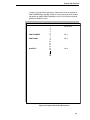
ANSI Emulation Default Settings
The ANSI factory settings are shown in Table 1 on page 24. Table 2 on page
25 lists additional factory settings for parameters provided by the LinePrinter
Plus® formatting menus. (The EMULATION menu options are described in
the User's Manual). Host control codes can override many of the settings for
these menu options.
23
Chapter
2
Overview
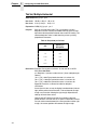
Table 1. ANSI Menu Option Factory Settings
Characteristic
24
Default Setting
CPI
10.0
LPI
6.0
Typeface
Data Processing
Proportional Spacing
Disable
Bold Print
Disable
Slash Zero
Disable
Left Margin
0 columns
Right Margin
0 columns
Top Margin
0 lines
Bottom Margin
0 lines
Form Length
66 lines
Form Width
136 characters
Define CR Code
CR = CR
Auto LF
Disable
Define LF Code
LF = CR + LF
Character Set
Latin 1 8859-1
Printer Select
ON = DC1/OFF = DC3
ESC c sequence
Enable
Reset Cmd CFG Ld
Disable
Received CR
Observe
Received Del
Observe
Private Mode
Set 2
Pos. on BC/OvrSz
Set to top
BC check digit
By host
Barcode Darkmode
Enable
PUM Default
Decipoints
Truncate PI Slew
Truncate at TOF
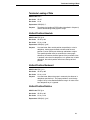
ANSI Emulation Default Settings
Table 2. LinePrinter+ Menu Option Factory Settings
Characteristic
Default Setting
CPI
10.0
LPI
6.0
Host Command
Enable
Typeface
Data Processing
Proportional Spacing
Disable
Bold Print
Disable
Italic Print
Disable
Slashed Zero
Disable
Text Position
Top of Line
Left Margin
0 columns
Right Margin
0 columns
Bottom Margin
0 lines
Perforation Skip
Disable
Form Length
11.0 inches
279.4 millimeters
66 lines
Form Width
13.6 inches
345.4 millimeters
136 characters
Reset Cmd CFG Ld
Disable
25
Chapter
2
Configuring the ANSI Emulation
Configuring the ANSI Emulation
Control codes transmit information other than printable characters to the
printer. They occupy the first 32 locations on the ASCII code chart (shown in
Appendix A) and are represented by two- or three-letter abbreviations. The
control code LF (decimal 10, hex 0A), for example, is usually interpreted as a
line feed. The response of the printer to other control codes will depend on the
emulation.
NOTE: Commands and control codes sent from a host system generally
override previous settings that result from the configuration menus.
However, any configuration settings from host control codes will be
gone once the printer is powered off (or reset to the default values),
unless you have saved them to memory using the configuration
menus. The User's Manual describes the configuration menu option
for saving changes.
Control Codes
ACK (Acknowledge 06H)
A received ACK is ignored. A transmitted ACK is used as part of the serial
interface ETX/ACK protocol. Upon the end of transmission of a block of data
terminated with an ETX, the host stops sending data until the printer interface
sends an ACK back to the host.
BEL (Bell 07H)
Receipt of a BEL code causes the beeper to sound for approximately 1
second.
BS (Backspace 08H)
A BS permits overprinting of characters. This command moves the character
position one character width to the left. If the current print position is at column
one, this command is ignored.
CR (Carriage Return 0DH)
If configured CR=CR+LF, the line will print, the paper will advance to the next
line, and the print position will move to column one.
If configured CR=CR, the print position is set at column one of the current line.
Any subsequent printable data preceding a paper motion command will
overstrike previously printed data. If it is set to ignore by the panel, then the
CR will be ignored.
DC1 (Device Control-1 11H)
Switches the printer from local to on-line mode and enables the printer to
receive data. If the serial interface is selected, DC1 acts as a data stream
control code. When the buffer is empty, the printer will send a DC1 (XON) to
the host computer, which will send data to the printer until the printer sends a
DC3 (XOFF) to the host computer.
26
Control Codes
DC3 (Device Control-3 13H)
Switches the printer from on-line to local mode. Causes the printer to ignore
all data except a DC1. If the serial interface is selected, DC3 acts as a data
stream control code. When the buffer is full, the printer will send a DC3
(XOFF) to the host computer, which will stop sending any data to the printer
until the printer sends a DC1 (XON) to the host computer.
DEL (Delete 7FH)
The delete character causes the character at this location in the current
character set to print. In graphics mode, the delete character is treated as
data. If it is set to ignore by the panel, then the DEL will be ignored.
ESC (Escape 1BH)
Escape signals the beginning of a special sequence. Characters in a valid
escape sequence are not printed.
FF (Form Feed 0CH)
Form Feed is a line terminator. All data received since the last line terminator
are printed and the paper is advanced to the next top-of-form.
HT (Horizontal Tab 09H)
An HT causes one of two actions. If a horizontal tab table is present, each HT
received is replaced by the number of space characters required to move the
current print position to the next tab location. If a horizontal tab table is not
present, a space is substituted for the HT character.
LF (Line Feed 0AH)
An LF code causes the line to be printed and the paper is advanced to the
next line, and the print position will remain at the same character column.
If the LF code is received in the horizontal graphics mode, paper is advanced
one or two dot rows depending on the vertical dot density.
If the LF is received in the vertical graphics format, paper is advanced after
the six dot rows are printed.
Vertical graphics spacing is 12 LPI for low vertical density and 24 LPI for high
vertical density.
VT (Vertical Tab 0BH)
A VT code causes the line to print and the paper to advance to the next tab
stop if a vertical tab is set.
If a tab position is at the current line, the paper advances to the next tab
position.
If there are no tab positions between the current line and the end of the form,
the paper advances to the next line at the current line spacing.
If the current position is at the bottom margin and a VT is sent, the paper will
advance to the next top-of-form.
27
Chapter
2
Configuring the ANSI Emulation
NOTE: Channel 12 is always used with the VT character. See Chapter 3,
“Vertical Page Formatting,” for more details.
Format for Control Code Descriptions
The following information is listed for each control code (where applicable):
Name
The title or function of the command.
ASCII Code The ASCII mnemonic for the command is shown for the printer
and the ANSI protocol. Command sequences are in 7-bit (ASCII)
form.
Hex Code
The code or command sequence in hexadecimal numbers.
Dec Code
The code or command sequence in decimal numbers.
Expression The control codes used in the BASIC programming language.
Purpose
The function(s) of the control code.
Discussion A discussion of the uses of the code or command sequence,
including exceptions or limitations to its use.
Example
A sample program written in BASIC programming language is
provided when it is possible to illustrate the effect of a control
code or if a specific syntax is required.
Examples are shown below of escape sequences as written in the text, shown
with parameters filled in, and written in the BASIC program language.
Tab Clear
ESC [p1 g
ESC[3g
LPRINT CHR$(27);“[3g”
Horizontal Tabs Set
ESC [p1;p2...pn u
ESC[648;1386;2808u
LPRINT CHR$(27);“[648;1386;2808u”
Expand Characters
ESC [p1;p2 SP B
ESC[200;200 B
LPRINT CHR$(27);“[200;200 B”
NOTE: If you specify parameters for a control code other than the ones
defined in the control code description, unpredictable results may
occur.
NOTE: Throughout this chapter the term “decipoints” is used. A decipoint
equals 1/720 inch and is used as a standard of measurement for
parameters associated with distances.
28
Format for Control Code Descriptions
Escape Control Codes Overview
Printer capability is greatly increased by the use of escape control code
sequences. Escape sequences always begin with the ASCII escape
sequence introducer, ESC (hex 1B). Many of the ASCII control codes
described in this chapter are escape sequences.
IMPORTANT
An Escape code can occur anywhere in the data stream and is acted
upon immediately if it precedes a valid command.
An ESC sequence introducer in the data stream signals the printer to wait for
special instructions, even if it is ready and printing. The character codes
following the ESC character tell the printer what to do.
NOTE: For readability, code sequences appear in this manual with spaces
inserted between command elements. Do not insert spaces between
code characters when you are programming unless the ASCII space
character (SP) is part of a code sequence. For example, a code
sequence printed in this manual as ESC [ 1 is programmed as ESC[1.
An escape sequence uses two or more bytes to define a specific printer
control function. The format for an escape sequence is
ASCII
ESC
X
p
Hex
1B
00 - 5F
0 - FF
Escape
Sequence
Introducer
Character(s)
Numerical
parameter(s)
After the ESC character are one or more characters which indicate the action
of the control code. One or more numerical parameters may in turn follow
these characters. For example, the sequence ESC [ p g tells the printer to
clear all horizontal tabs if p is a 3, or to clear all vertical tabs if p is a 4.
If the characters following the ESC code are not within the defined ranges, or
if they are within the defined ranges but are not recognized as a function of
this printer, the entire sequence is ignored.
29
Chapter
2
Configuring the ANSI Emulation
Control Codes Index
The following index lists the control codes by ASCII sequence, function and
page number. Some control code functions can also be selected at the control
panel.
FUNCTION
Character Sets, International
Expanded Mode
Forms Length, Top Margin,
Bottom Margin
Graphic Rendition
Horizontal Position Absolute
Horizontal Position Backward
Horizontal Position Relative
Horizontal / Vertical Position
Absolute
Line Spacing
Margins, Left and Right
Private Mode, Disable
Private Mode, Enable
Proportional Print Mode
Resetting
Subscript
Superscript
Tab, Clear
Tab Set, Multiple Horizontal
Terminate Loading of Data
Vertical Position Absolute
Vertical Position Backward
Vertical Position Relative
Vertical Tab Set
SEQUENCE
PAGE
ESC[p1 x
ESC[p1;p2 SP B
31
33
ESC[p1;p2;p3 r
ESC[p1;p2...;pn m
ESC[p1 ‘
ESC[p1 j
ESC[p1 a
34
35
36
36
36
ESC[p1;p2 f
ESC[p1;p2 SP G
ESC[p1;p2 s
ESC[>5l
ESC[>5h
ESC[6 m
ESC c
ESC K
ESC L
ESC[p1 g
ESC[p1;p2...;pn u
ESC \
ESC[p1 d
ESC[p1 k
ESC[p1 e
ESC[p1 v
37
37
38
39
39
39
40
41
41
41
42
43
43
43
43
44
ESC P
ESC[p1 b
ESC[p1;p2;p3 q
ESC[p1 t
ESC[p1;p2...;p10}
48
48
49
50
50
ESC[p1 |
58
Graphics Commands
Dot Graphics
Repeat Graphics Character
Select Graphics Mode
Entering and Exiting Bar Codes
Setting Bar Code Parameters
Oversized Character
Font Option
Vertical Formatting Commands
Begins 12-channel EVFU
table loading
Skip to Channel Command
30
ESC ]!
ESC[p1 ! p
Chapter 3
Chapter 3
Character Sets, International
Character Sets, International
ASCII Code ESC [p1 x
Hex Code
1B 5B p1 78
Dec Code
27 91 p1 120
Expression CHR$(27);“[p1x”;
Purpose
Selects the international character set specified by p1, which is
shown in Table 3. When an international character set is
selected, it is printed in whatever font style and enhancement
mode may be in effect. The default set is Latin 1 8859-1.
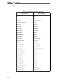
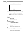
Table 3. ANSI International Character Sets
p1
Country
0
USA (ISO standard)
1
German
2
French A
3
French B
4
French Canadian
5
Dutch (Netherlands)
6
Italian
7
United Kingdom
8
Spanish
9
Danish/Norwegian A
10
Danish/Norwegian B
11
Danish/Norwegian C
12
Danish/Norwegian D
13
Swedish/Finnish A
14
Swedish/Finnish B
15
Swedish/Finnish C
16
Swedish/Finnish D
17
Swiss
18
USA (ISO standard)
19
Yugoslavian
20
UK A (United Kingdom A)
21
Turkish
22
Greek
31
Chapter
2
Configuring the ANSI Emulation
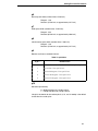
Table 3. ANSI International Character Sets (continued)
p1
32
Country
23
ISO Italian
24
ISO Spanish
8573
IBM PC set 2, Greek
8574
DEC Multinational
8575
Roman 8
8576
Polish Mazurka
8577
IBM PC-set 2 Turkish
8591
ISO 8895-1 Latin Alphabet #1
8592
ISO 8895-2 Latin Alphabet #2
8593
ISO 8895-3 Latin Alphabet #3
8594
ISO 8895-4 Latin Alphabet #4
8595
ISO 8895-5 Latin/Cyrillic
8596
ISO 8895-6 Latin Arabic
8597
ISO 8895-7 Latin Greek
8598
ISO 8895-8 Latin Hebrew
8599
ISO 8895-9 Latin South Europe II
437
IBM PC Set 2
850
IBM PC Multilingual SET 2
851
Microsoft Code Page 851 Greece
852
Microsoft Code Page 852 Slavic
853
Microsoft Code Page 853 Turkey 1
855
Microsoft Code Page 855 Cyrillic
860
Microsoft Code Page 860 Portugal
863
Microsoft Code Page 863 French Canadian
864
Microsoft Code Page 864 Arabic
865
Microsoft Code Page 865 Nordic
866
Microsoft Code Page 866 Russian
867
Microsoft Code Page 867 Turkey 2
5915
ISO 8859-15 Latin 0
Expanded Mode
Expanded Mode
ASCII Code ESC [p1;p2 SP B
Hex Code
1B 5B p1 3B p2 20 42
Dec Code
27 91 p1 59 p2 32 66
Expression CHR$(27);“[p1;p2 B”;
Purpose
Modifies the vertical (p1) and horizontal (p2) character size of all
characters following the sequence and stays in effect until
changed or canceled. Expansions of X3, X5, X6, and X7 are
invalid for p2.
Discussion An invalid or zero parameter selects the normal (X1) expansion.
If a parameter is missing, the former value is used. Valid p1 and
p2 values are the following:
X1 0-199 (default)
X2 200-299
X3 300-399*
X4 400-499
X5 500-599*
X6 600-699*
X7 700-799*
X8 800-up
* Not valid for horizontal expansion
Horizontal and vertical expansion are independent, and different
values can be mixed in a line. Mixed sizes within a line are topjustified. Since the line feed is based on the size of the
characters in the final pass, the largest sized characters on a line
should be printed last to avoid printing over other characters.
Examples:
ESC [;200 B
ESC [200;200 B
ESC [800;400 B
X1 Vert. expansion, X2 Horiz. expansion
X2 Vert. expansion, X2 Horiz. expansion
X8 Vert. expansion, X4 Horiz. expansion
When the printer is printing vertically expanded characters, blank
lines (lines with non printed characters) are not expanded from
the current LPI setting.
33
Chapter
2
Configuring the ANSI Emulation
Forms Length, Top Margin, Bottom Margin
ASCII Code ESC [p1;p2;p3 r
Hex Code
1B 5B p1 3B p2 3B p3 72
Dec Code
27 91 p1 59 p2 59 p3 114
Expression CHR$(27); “[p1;p2;p3r”;
Purpose
Defines the form.
p1 = Form length (in decipoints). Maximum allowable length is
22 inches (15,840 decipoints)
p2 = Top margin from top of page. Top of page to first print line.
p3 = Bottom margin from end of page. The last print line to
bottom of page.
The default parameters are for a 12 inch long form with a top
margin of zero and a bottom margin of zero.
Discussion The printer keeps track of these vertical positions to the nearest
half point (5 decipoints).
1 decipoint = 1/720 inch
1 point = 10 decipoints (10/720 inch)
1/2 point = 5 decipoints (5/720 inch)
Examples
ESC [r
default values of 12 inch form length, zero top and bottom
margins
ESC [8280r 11.5 inch form length, default top and bottom margins of zero
ESC [;720r default length of 12 inches, top margin of one inch, default
bottom margin of zero
ESC [;;720r default length of 12 inches, default top margin of zero and a oneinch bottom margin
ESC [7920;360;360r
11 inch form length, 1/2 inch top and bottom margins
34
Graphic Rendition
Graphic Rendition
ASCII Code ESC [p1;p2...;pn m
Hex Code
1B 5B p1 3B p2 ... 3B pn 6D
Dec Code
27 91 p1 59 p2 ... 59 pn 109
Expression CHR$(27);“[p1;p2...;pn m”;
Purpose
Sets the character type and enhancements, such as boldface,
underscore, expanded, or proportional. One font designator plus
any number of enhancements can be entered in the escape
sequence using the parameter values in Table 4.
Discussion If the requested font is not installed, the Data Processing font will
be activated. When a new font is selected, the horizontal
spacing is initially set to the default spacing (10 cpi).
This sequence is also valid in graphics.
Table 4. Character Types and Enhancements
Parameter
Enhancement
0
Normal Mode
1
Bold/shadow
4
Underline
5
2X horizontal expansion (Note: This mode cancels any
horizontal or vertical expansion previously set. Can be
cleared by either a parameter value of 0 in this sequence
or by ESC[p1;p2 SP B.)
6
Proportional printing (Note: This mode is valid for all cpi
values, expansion values, print modes, and fonts except
high speed draft and character graphics.)
10
Default font (Data Processing)
11
Gothic draft font
12
Character graphics/mathematical symbol font
13
Gothic NLQ font
14
Courier NLQ font
15
High speed draft font
16
OCR-A
17
OCR-B
18
Italic NLQ font
19
Correspondence
35
Chapter
2
Configuring the ANSI Emulation
For Gothic NLQ font underlined:
ESC [4;13m
To cancel underlining and retain Gothic NLQ
send one of the following:
ESC [;13m
ESC [0m
ESC [0;13m
ESC [;m
Horizontal Position Absolute
ASCII Code ESC [ p1 ‘
Hex Code
1B 5B p1 60
Dec Code
27 91 p1 96
Purpose
Line terminator. Sets horizontal position to value specified by p1
in decipoints. If the parameter value is omitted or greater than
9504 decipoints, the command is ignored.
Horizontal Position Backward
ASCII Code ESC [ p1 j
Hex Code
1B 5B p1 6A
Dec Code
27 91 p1 106
Purpose
Line terminator. Moves the print position to the left of the current
position by the number of decipoints specified in p1. If the
parameter value is omitted, the command is ignored. If the
parameter value exceeds the distance to the left margin, the new
position will be the left margin.
Horizontal Positive Relative
ASCII Code ESC [ p1 a
36
Hex Code
B 5B p1 61
Dec Code
27 91 p1 97
Purpose
Line terminator. Moves the print position to the right of the
current position by the number of decipoints specified in p1. If
the parameter value is omitted, the command is ignored. If the
parameter value exceeds the distance to the right margin, the
new position will be the right margin.
Horizontal/Vertical Position Absolute
Horizontal/Vertical Position Absolute
ASCII Code ESC [ p1; p2 f
Hex Code
1B 5B p1 3B p2 66
Dec Code
27 91 p1 59 p2 102
Purpose
Line terminator. Sets vertical position to value specified by p1,
and the horizontal position to the value specified by p2 (both
values are specified in decipoints. This command can also be
used to set the print position inside margins. The vertical
position cannot exceed the form length, and the horizontal
position cannot exceed 9504 decipoints.
Line Spacing
ASCII Code ESC [p1;p2 SP G
Hex Code
1B 5B p1 3B p2 20 47
Dec Code
27 91 p1 59 p2 32 71
Expression CHR$(27);“[p1;p2 G”;
Purpose
Sets line spacing (p1) and character spacing or pitch (p2) in
decipoints.
Discussion Horizontal spacing (p2) is dependent on the font selected.
Values outside the range of a particular font will be ignored.
Commonly used line spacings are listed in Table 5 and Table 6.
Table 5. Common p1 Values
LPI
p1 (decipoints)
3
240
4
180
6
120
8
90
Table 6. Common p2 Values
CPI
p2 (decipoints)
10
72
12
60
13.3
54
15
48
16.7
43
37
Chapter
2
Configuring the ANSI Emulation
Margins, Left and Right
ASCII Code ESC [p1;p2 s
Hex Code
1B 5B p1 3B p2 73
Dec Code
27 91 p1 59 p2 115
Expression CHR$(27);“[p1;p2s”;
Purpose
The p parameters are distances from the left edge of the
printable area of the paper in decipoints. They are internally
converted to column positions based on the current CPI setting.
The first print area will be one column to the right of the left
margin.
NOTE: The margins set with this sequence begin at the first physical print
position, not at the edge of the paper.
Discussion When operating at 10 CPI, the escape sequence ESC
[720;8784s will produce a one-inch (10 column) left margin with
column 11 as the first printable position. The print line length is
8784 decipoints minus 720, or 8064 decipoints (11.2 inches, 112
columns). If the normal print area of 13.2 inches is available, the
right margin is one inch. The last column represented by p2 is
the last print position and the right margin begins in the next
column.
Left and right margin default values are column zero and the
highest column number in use depending on the CPI setting,
shown below. This escape sequence is valid in graphics but
does not apply to bar codes. Default margins may be set by
using ESC [s.
Left Margin = column 0 minus Right Margin
10 CPI = column 136
12 CPI = column 163
13.3 CPI = column 181
15 CPI = column 204
16.7 CPI = column 226
When printing in proportional mode or line mixing, the margins
are converted to absolute positions for that line. If the printer
receives this command anywhere in a printable line, the
command will affect that line and subsequent printable lines.
38
Private Mode, Disable
Private Mode, Disable
ASCII Code ESC [>5l (lowercase “L”)
Hex Code
1B 5B 3E 35 6C
Dec Code
27 91 62 53 108
Expression CHR$(27); “[>5l”;
Purpose
Disables private mode.
Discussion Selects character set 1 of the selected 8 bit international
character set. With non-ISO character sets, hex codes 20-7F
and A0-FF are printable. Hex codes 80-9F are duplicates of 001F. For ISO character sets hex codes 80-9F are treated as Nulls.
Private Mode, Enable
ASCII Code ESC [>5h
Hex Code
1B 5B 3E 35 68
Dec Code
27 91 62 53 104
Expression CHR$(27): “[>5h”;
Purpose
Enables private mode.
Discussion Selects character set 2 of the selected 8 bit international
character set. Allows printing of hex codes 15, 20-7E and 80-FF.
Proportional Print Mode
ASCII Code ESC [6 m
Hex Code
1B 5B 36 6D
Dec Code
27 91 54 109
Expression CHR$(27);“[6m”;
Purpose
Sets proportional printing where each character has its own
width.
Discussion All fonts and modes allow proportional printing. The
proportionalized character graphics font, however, is the same
as the normal character graphics font.
39
Chapter
2
Configuring the ANSI Emulation
Resetting
ASCII Code
Hex Code
Dec Code
Expression
Purpose
ESC c
1B 63
27 99
CHR$(27);“c”;
Resets the printer’s configuration parameters. Depending on
which option was selected in the “Reset Cmd CFG Ld” menu,
the parameters are set to the factory default configuration,
power-up configuration, or the current configuration. If “Reset
Cmd CFG Ld” is disabled in the menu, the hardcoded
parameters shown in Table 7 are set.
Discussion The following attributes, which are not part of the configuration,
are also reset:
Character rotation is reset to no rotation.
Character expansions are set to 1x1.
Subscript and superscript are turned off.
Underscoring is turned off.
Plot mode is terminated.
The horizontal and vertical tabulation tables are cleared.
The default EVFU table is loaded.
Bar code parameters are set to default values.
Graphic line density is set to 60 horizontal DPI x 72 vertical DPI.
The current line is set as the top-of-form (TOF) position.
Table 7. Hardcoded Reset Values
Parameter
40
Setting
Font style
Data processing
Character size
1 x vertical; 1 x horizontal
Character pitch
10 CPI
Country selection
Latin 1 8859-1
Line spacing
6 LPI
Partial Line up
Reset
Partial Line down
Reset
Bold print
Disabled
Underline mode
Disabled
Expanded mode
Disabled
Proportional mode
Reset
Horizontal tab table
Empty
Left margin
None - column 0
Right margin
None - Maximum
Page size
7920 decipoints/ 66 lines/ 11 inches
Top margin
None
Bottom margin
None
Forms position
Top-of-form = current position
Vertical tab table
Empty
Vertical format unit
Default
Graphics density
60 Horizontal DPI, 72 Vertical DPI
VFU load in progress
Exit (nothing saved)
Bar code mode
Disabled
Dot graphics
Disabled
Subscript
Subscript
ASCII Code ESC K
Hex Code
1B 4B
Dec Code
27 75
Expression CHR$(27);“K”;
Purpose
Moves the print line down 3/72 inch for subscript printing. Also
used to return to original print line if the Superscript printing
command was sent.
Superscript
ASCII Code ESC L
Hex Code
1B 4C
Dec Code
72 76
Expression CHR$(27);“L”;
Purpose
Moves the print line up 3/72 inch for superscript printing. Also
used to return to original print line if the Subscript printing
command was sent.
Discussion Both Superscript and Subscript can be printed on the same line.
They cannot be used in succession to advance or reverse the
paper to another line. They can be used in pairs to change from
Superscript to Subscript or Subscript to Superscript.
NOTE: If you do not send a command to return the print position to the
original baseline, subsequent lines will be misaligned.
The ESC K and L commands are ignored in graphics.
Tab, Clear
ASCII Code ESC [p1 g
Hex Code
1B 5B p1 67
Dec Code
27 91 p1 103
Expression CHR$(27);“[p1g”;
Purpose
Clears horizontal or vertical tab stops based on the p1 value:
p1 = 3 Clear all horizontal tabs
p1 = 4 Clear all vertical tabs
This command is valid in graphics.
41
Chapter
2
Configuring the ANSI Emulation
Tab Set, Multiple Horizontal
ASCII Code ESC [p1;p2...;pn u
Hex Code
1B 5B p1 3B p2 ... 3B pn 75
Dec Code
27 91 p1 59 p2 ... 59 pn 117
Expression CHR$(27);“[p1;p2...;pn u”
Purpose
Sets up to 22 horizontal tabs. The p parameters are set in
decipoints and are normally converted internally to the nearest
equivalent column position based on the current CPI setting. The
absolute decipoint value is used when the printer is printing
proportional characters.
Table 8. Decipoints per Column
CPI
Spacing in
Decipoints
10
72
12
60
13.3
54
15
48
16.7
43
Discussion Example: Placing tabs at columns 10, 20, and 40 at 10 CPI.
ESC [648;1386;2808u
p in decipoints = (column number minus 1) times (decipoints per
column)
(10 - 1)(72) = 648 First printed character is in column 10
(20 - 1)(72) = 1368 First printed character is in column 20
(40 - 1)(72) = 2808 First printed character is in column 40
Appendix B contains a conversion table for decipoint
calculations.
If more than 22 tabs are set, the highest numbered tabs (farthest
right) will be pushed out of the table. Tabs set beyond the right
margin are not usable. Moving the right margin beyond these
settings will make them active.
Control code HT (09H) moves the print position to the next
preset location. If no tabs are set, a space is substituted. If there
are tabs set but none between the current position and the right
margin, the current position will become the right margin.
42
Terminate Loading of Data
Terminate Loading of Data
ASCII Code ESC \
Hex Code
1B 5C
Dec Code
27 92
Expression CHR$(27);“\”;
Purpose
Terminates the loading of EVFU tables (described in Chapter 3)
and the downloading of dot graphics strings.
Vertical Position Absolute
ASCII Code ESC [p1 d
Hex Code
1B 5B p1 64
Dec Code
27 91 p1 100
Expression CHR$(27);“[p1d”;
Purpose
Line terminator. Sets vertical position to specified p1 value in
decipoints, moving paper forward or backward to the new
position. Can be used to print inside top and bottom margins.
The specified position must be set within the current page;
otherwise, the command will be ignored. If the parameter value
is omitted, is less than five decipoints, or is greater than 15,840
decipoints, the vertical position will move to the top-of-form
position.
Vertical Position Backward
ASCII Code ESC [ p1 k
Hex Code
1B 5B p1 6B
Dec Code
27 91 p1 107
Purpose
Line terminator. Moves the paper in reverse by the distance in
decipoints specified in p1. The paper position is set to the top
margin if the p1 value would exceed the margin. A value of 5 or
less decipoints for p1 is ignored.
Vertical Position Relative
ASCII Code ESC [p1 e
Hex Code
1B 5B p1 65
Dec Code
27 91 p1 101
Expression CHR$(27);“[p1e”;
43
Chapter
2
Configuring the ANSI Emulation
Purpose
Line terminator. Moves the current vertical position by the
specified p1 number of decipoints as shown in Table 9.
Table 9. Vertical Position
Decipoint Value
Movement in Inches
missing or 0-4
no movement
5-9
1/144 inch
10-14
2/144 inch
15-19
3/144 inch
...
15, 840 or greater
...
22 inches
Vertical Tab Set
ASCII Code ESC [ p1;p….; v
44
Hex Code
1B 5B p1 3B p… 3B 76
Dec Code
27 91 p1 59 p… 59118
Purpose
Set up to 12 vertical tabs. The tabs values are in decipoints. If
more than 12 tabs are set, the 12 tabs nearest to the top of form
will be retained. If a tab is set in the top margin, it will be stored,
but not active until the margin is moved. If a tab is set beyond
the bottom margin, an attempt to move to that tab will move the
paper to the next top of form.
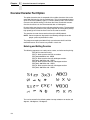
Dot Patterns And Densities
Graphics
The ANSI emulation graphics mode provides both horizontal and vertical dot
placement plotting methods. These methods enable the printing of ASCII
characters in their binary code form. Since each character has a unique
pattern of 1's and 0's (dots and voids) that make up its binary code, the
correct placement of these binary forms enables you to form larger images.
For clarity in the text, a binary 1 (a printed dot) will be shown as an X and a
binary 0 (empty dot position) will be shown as a 0.
In the graphics mode, only the low order six bits of a seven-bit character are
used (bits 1-6). Looking at an ASCII code chart, the question mark character
(?) is represented by the binary number 0111111 (bit 7 - bit 1). Since only the
first 6 bits are used, a “?” would print six dots on the paper. A lowercase “j” is
represented by 101010 which would print the following:
Horizontal Graphics / Vertical Graphics
0X0X0X0 LSB
LSB MSBX
0
X
0
X MSB
NOTE: When plotting data, the Least Significant Bit (LSB), Bit 1, is printed
first (left or top bit position) and the Most Significant Bit (MSB), Bit 6,
is printed last (right or bottom bit position).
Notice that in the horizontal graphics mode, the characters are printed on a
single horizontal dot row. In vertical graphics mode, the characters are printed
six dots high, a character per dot column.
Using a series of question mark (that prints all dots) characters in a horizontal
graphic produces a one dot high solid line across the paper. The same
character in vertical graphics mode products a six dot high band across the
paper.
Graphs, charts, and pictures can be produced by repeating, omitting, and
mixing characters across a page.
Dot Patterns And Densities
Table 10 lists the dot patterns for each of the ASCII characters. Each ASCII
character represents six dot positions (or dots) and their spacing is dependent
on the density selected. With a density of 60 and 70 DPI, the dots are spaced
1/60 and 1/70 inch apart respectively. At 120 and 140 CPI, each character
represents six dots spaced 1/120 and 1/140 inch apart. At 180 and 210 DPI
densities, the dots are spaced 1/180 and 1/210 inch apart.
The ASCII characters needed to cover all dot/void combinations are listed in
the chart below. Other valid character combinations (although repeat patterns
of the characters in the chart) are hex 09-13 and hex 20-3E.
45
Chapter
2
Graphics
NOTE: In Table 10, x=dot and o=no dot.
Table 10. ASCII Character Dot Patterns
46
Char
Hex
Value
Dots
654321
Char
Hex
Value
Dots
654321
@
40
oooooo
.
60
xooooo
A
41
ooooox
a
61
xoooox
B
42
ooooxo
b
62
xoooxo
C
43
ooooxx
c
63
xoooxx
D
44
oooxoo
d
64
xooxoo
E
45
oooxox
e
65
xooxox
F
46
oooxxo
f
66
xooxxo
G
47
oooxxx
g
67
xooxxx
H
48
ooxooo
h
68
xoxooo
I
49
ooxoox
i
69
xoxoox
J
4A
ooxoxo
j
6A
xoxoxo
K
4B
ooxoxx
k
6B
xoxoxx
L
4C
ooxxoo
l
6C
xoxxoo
M
4D
ooxxox
m
6D
xoxxox
N
4E
ooxxxo
n
6E
xoxxxo
O
4F
ooxxxx
o
6F
xoxxxx
P
50
oxoooo
p
70
xxoooo
Q
51
oxooox
q
71
xxooox
R
52
oxooxo
r
72
xxooxo
S
53
oxooxx
s
73
xxooxx
T
54
oxoxoo
t
74
xxoxoo
U
55
oxoxox
u
75
xxoxox
V
56
oxoxxo
v
76
xxoxxo
W
57
oxoxxx
w
77
xxoxxx
X
58
oxxooo
x
78
xxxooo
Y
59
oxxoox
y
79
xxxoox
Z
5A
oxxoxo
z
7A
xxxoxo
[
5B
oxxoxx
{
7B
xxxoxx
\
5C
oxxxoo
|
7C
xxxxoo
]
5D
oxxxox
}
7D
xxxxox
^
5E
oxxxxo
~
7E
xxxxxo
Horizontal Format
Table 10. ASCII Character Dot Patterns (continued)
Char
Hex
Value
Dots
654321
Char
Hex
Value
Dots
654321
-
5F
oxxxxx
?
3F
xxxxxx
Horizontal Format
Graphics data printed in horizontal format comprise a stream of bytes from left
to right across each dot row.
Table 11 shows that byte 1 (or character 1) in row 1 will print its six bits from
left to right in a single dot row. The next byte (byte 2) prints its six bits,
representing a character, in the same dot row across the page.
Table 11. Horizontal Format
Byte →
Row ↓
Byte 1
Byte 2
Byte n
1
2
3
.
.
6
123456
123456
123456
.
.
123456
123456
123456
123456
.
.
123456
123456
123456
123456
.
.
123456
Vertical Format
In vertical format, each byte (or character) occupies six dot rows of one
column. Each character is one dot wide and six dots high. The next character
(byte 2) is printed beside the first moving from left to right across the page.
Table 12. Vertical Format
Byte →
1
2
3
... n
Row
bit
bit
bit
... bit
1
2
3
4
5
6
1
2
3
4
5
6
1
2
3
4
5
6
1
2
3
4
5
6
... 1
... 2
... 3
... 4
... 5
... 6
47
Chapter
2
Graphics
Other Graphics Considerations
•
In horizontal format, an LF causes the paper to advance one or two dot
rows based on the vertical dot density.
•
In vertical format, the paper is advanced as the six dot rows are printed.
Spacing is essentially 12 LPI for low density and 24 LPI for high density
graphics.
•
Escape sequences ending with the following characters are ignored in
graphics mode:
KLPQ q
t}]!SP B
•
Escape sequences ending with the following characters are valid while
the printer is in graphics mode:
Ggubmx
dr!pes
Dot Graphics
ASCII Code ESC P
Hex Code
1B 50
Dec Code
27 80
Expression CHR$(27);“P”;
Purpose
Enters dot graphics mode at the density and format previously
selected by the ESC [p1;p2;p3 q sequence.
Discussion Following this sequence the printer prints discrete dots and
leaves spaces based on the 1's and 0's in the low order six bits
of each byte received, forming graphic dot rows from left to right.
Exit from dot graphics mode is via ESC \.
Repeat Graphics Character
ASCII Code ESC [p1 b
Hex Code
1B 5B p1 62
Dec Code
27 91 p1 98
Expression CHR$(27);“[p1b”;
Purpose
Repeats the single preceding character p1 times.
Discussion If p1 is 0 or unspecified, it is set to 1. The maximum value for p1
is 32,767. Only valid in the dot graphics mode.
48
Select Graphics Mode
Select Graphics Mode
ASCII Code ESC [p1;p2;p3 q
Hex Code
1B 5B p1 3B p2 3B p3 71
Dec Code
27 91 p1 59 p2 59 p3 113
Expression CHR$(27);“[p1;p2;p3q”;
Purpose
Selects the graphics mode format and horizontal/vertical density
for dot graphics.
This sequence must be sent before entering the graphics mode
with ESC P.
Discussion The first parameter selects the graphics mode (Table 13). The
second parameter selects the vertical dot spacing (Table 14)
and the third selects the horizontal dot spacing (Table 15).
Table 13. Select Graphics Mode
p1
Selects Graphics Mode
0
Vertical Format @ 70H x 72V DPI*
1
Invalid, default to 70H x 72V DPI
2
Vertical Format @ 140H x 144V DPI
3
Invalid, default to 70H x 72V DPI
4
Horizontal Format (plot mode)
*p2 and p3 are ignored in this mode.
Table 14. Select Vertical Dot Spacing
p2
Selects Vertical Density
0 through 6
144 DPI
7+
72 DPI
Table 15. Select Horizontal Dot Spacing
p3
Selects Horizontal Density
0 through 3
240 DPI - 544 characters per line
4
180 DPI - 408 characters per line
5
140 DPI - 317 characters per line
6 through 7
120 DPI - 272 characters per line
8 through 10
70 DPI - 158 characters per line
11+
60 DPI - 136 characters per line
49
Chapter
2
Bar Codes
Bar Codes
You can generate 17 different styles of bar codes and do the following:
•
•
•
•
all except POSTNET can be rotated 90, 180, or 270 degrees
print with or without a human readable line (HRL)
adjust the symbol size
adjust the density
The following examples show the correct control code syntax and the code
written in the BASIC program language.
Entering and Exiting Bar Codes
To print bar codes, you must first activate the bar code mode:
ESC[3t
LPRINT CHR$(27);“[3t”;
All data following this sequence will be interpreted and printed as bar codes.
To exit:
ESC[0t
LPRINT CHR$(27);“[0t”;
Setting Bar Code Parameters
You can set the style, height, spacing, orientation, and print density. There
are 10 parameters (p1 - p10) to specify. The default values are shown on the
second line below and in Table 16.
ESC [p1;p2;p3;p4;p5;p6;p7;p8;p9;p10}
LPRINT CHR$(27);“[4;9;1;2;6;2;6;2;0;0}”;
Table 16. Default Bar Code Parameters
If pn = Value
50
Enables
p1 = 4
Code 3/9
p2 = 9
3/4” high bar code
p3 = 1
Human readable line
p4 = 2
Narrow bar width 2/20”
p5 = 6
Wide bar width 6/120”
p6 = 2
Narrow space width 2/120”
p7 = 6
Wide space width 6/120”
p8 = 2
Intercharacter space width 2/120”
p9 = 0
No rotation. Use current font.
p10 = 0
Horizontal print density 60 dpi
Setting Bar Code Parameters
NOTE: If no values are set for parameters p2-p10, the default values will be
used. If you have sent a value from the host, this value is active until
you replace it or the printer is reset.
In this example the following parameters are changed on Line 10:
p1 = style (Code 128)
p2 = height (3/12 inch)
p9 = human readable font (use special font)
The semicolons are “place holders” for the parameters not being changed.
A list of the 10 parameters and their values follows.
p1
Selects the style.
Table 17. p1 Values
If p1 =
Style
0
Interleaved 2/5
1
German PTT Interleaved 2 of 5
2
Matrix 2 of 5
3
IATA 2 of 5
4
Code 3/9
5
EAN-8
6
EAN-13
7
Code 11
8
Reserved
9
Codabar a/t
10
Codabar b/n
11
Codabar c/*
12
Codabar d/e
13
UPC A
14
UPC E
51
Chapter
2
Bar Codes
Table 17. p1 Values (continued)
If p1 =
Style
15
Code 93
16
Code 128
17
Reserved
18
Reserved
50
POSTNET
NOTE: Parameters p2 through p10 are invalid for POSTNET. Do not change
the default values; otherwise, they will be retained in memory and will
affect the other bar code styles.
NOTE: The dimensions that follow apply to bar codes that are printed at 0
and 180 degrees rotation. If you are printing bar codes that are
rotated 90 or 270 degrees, the dimensions will be compressed by a
6:5 ratio.
p2
Bar code height in 1/12 inch increments. Does not include the human
readable line.
Min.:1 = 1/12 inch
Max.:120 = 10 inch
Default:9 = 9/12 inch (or 3/4 inch)
p3
Printing the human readable line.
0 = Do not print the human readable line
1 = Default. Print the human readable line
p4
Narrow bar width (number times 1/120”).
Range:2 - 126
Default:2 (2/120 inch, or approximately .017 inch)
p5
NOTE: p5, p7, and p8 are not programmable in some bar code styles.
Wide bar width (number times 1/120”).
Range:2 - 254
Default:6 (6/120 inch, or approximately .050 inch)
52
Setting Bar Code Parameters
p6
Narrow space width (number times 1/120 inch).
Range:2 - 126
Default:2 (2/120 inch, or approximately .017 inch)
p7
Wide space width (number times 1/120 inch).
Range:2 - 254
Default:6 (6/120 inch, or approximately .050 inch)
p8
Intercharacter space width (number times 1/120 inch).
Range:2 - 126
Default:2 (2/120 inch, or approximately .017 inch)
p9
Rotation and human readable line font.
Table 18. p9 Values
If p9 =
Rotation/Font
0
Default. No rotation. Use the current font, cpi, and lpi.
1
No rotation. Use special font.
2
Rotate 90 degrees. Use special font.
3
Rotate 180 degrees. Use special font.
4
Rotate 270 degrees. Use special font.
p10
Horizontal print density
0 = 60 dpi horizontal by 144 dpi vertical
1 = 120 dpi horizontal by 144 dpi vertical
120 dpi is the default for bar code styles 5, 6, 13, and 14. 60 dpi is the default
for the other bar code styles.
53
Chapter
2
Bar Codes
Human Readable Line (HRL)
The human readable line, which is .10 inch below the bar code, will print in
any of the available fonts as long as the bar code is not rotated. (Rotated bar
codes use a special font.)
To enable bold, underlining or expanded print on the human readable line,
you must first print the bar code without the line. Exit the bar code mode.
Then, print the line in normal text mode with the specified enhancements.
Spacing between Bar Codes
The space before and after a bar code is referred to as the “quiet zone” and
equals .25 inch. If two horizontal bar codes are placed side by side, the
designated minimum distance between them is .50 inch.
You can insert commas, spaces, and horizontal tabs as delimiters to separate
the bar codes:
•
•
•
comma - no extra space added
space - adds .10 inch for a total .60 inch quiet zone
tab - adds appropriate number of empty spaces to reach next tab
Examples
The comma does not add any space; therefore, only .50 inch separates the
bar codes.
A space character adds .1”. You can insert multiple space characters.
54
Bar Code Readers
To space bar codes across a page, insert horizontal tabs. Line 10 sets
horizontal tabs at 1440 and 2880 decipoints (2 and 4 inches). The Horizontal
Tab codes in lines 40 and 60 cause a jump to the next tab.
If horizontal tabs have not been set, a Horizontal Tab code is considered a
space, adding .1 inch between the bar codes. Total separation is .6 inchwhen
the Horizontal Tab is added to the quiet zones.
Line 10 clears all previously set horizontal tabs for this example.
Bar Code Readers
Use a bar code reader that can read medium or low density bar code
symbols. Avoid readers with apertures less than 7 mils (.007 inch or .18mm).
55
Chapter
2
Bar Codes
Test Program
Run this test to check the printer's ability to print bar codes when more
complicated programs are not producing results.
Line 10 turns on the bar code mode
Line 20 contains the bar code data
Line 30 exits the bar code mode
Vertical Bar Codes
You can rotate bar codes. The following examples show various ways of
creating bar codes and adjusting spacing.
Line 10 sets parameter p9 for 90 degree rotation using the
special font for the HRL
Line 20 turns on the bar code mode
Line 30 contains bar code data
Line 40 turns off the bar code mode
56
Vertical Bar Codes
Commas and spaces function as they do for horizontal bar codes. A comma
does not add any space, and a space adds .1” between the bar codes. The
quiet zones rotate with the symbol leaving almost no horizontal separation
between bar codes on the same line.
Line 10 either enables or disables printing of the human readable line.
Commas with Human Readable Line:
Commas without Human Readable Line:
Spaces with Human Readable Line:
Spaces without Human Readable Line:
57
Chapter
2
Oversize Character Font Option
Oversize Character Font Option
The optional oversize font is composed with scalable characters that can be
expanded 156 times the size of standard fonts. This will accommodate letters
up to 15.25 inches (388mm) high by 13 inches (330mm) wide. The minimum
character size (default setting) is two times the size of standard characters.
Oversize characters can also be rotated 90, 180, or 270 degrees.
Do not mistake oversize characters with expanded characters. The expanded
character feature (standard in your printer) expands all existing fonts (except
high speed) up to 8 times the normal size and cannot be rotated.
The oversize character feature works with only the ANSI protocol.
NOTE: Control sequences displayed in the following examples show the
proper syntax required from the host.
The program examples provided will help you to become familiar with the
oversized feature. All characters are printed in actual size.
Entering and Exiting Oversize
The following sequences are used to enter, rotate, and exit oversize printing.
ESC [0| Exit oversize Printing.
ESC [1| Select oversize font with no rotation.
ESC [300; 300 BSize 3x3 : ABCD
ESC [2| Select oversize font with 90-degree rotation.
ESC [300 ; 300 BSize 3x3 : ABCD
ESC [3| Select oversize font with 180-degree rotation.
ESC [300 ; 300 BSize 3x3 : ABCD
ESC [4| Select oversize font with 270-degree rotation
ESC [300 ; 300 BSize 3x3 : ABCD.
Text can be rotated in the following order from top to bottom: no rotation, 90
degrees, 180 degrees, 270 degrees.
58
Selecting Size
Selecting Size
ESC [p1;p2 B is the sequence used to set the vertical (p1) and horizontal (p2)
size of the oversize characters. A p1 value of 300 would increase the vertical
size of the character 300% or 3 times.
ESC[p1;p2 B
CHR$(27);“[300;300 B;
The last two digits of each parameter are necessary to comply with the ANSI
standard, but are ignored by the printer. Using the above example for p1, any
three digit number starting with 3 (300-399) will be interpreted as 3 times
normal size. Likewise, 400-499 equals 4 times, 1200-1299 equals 12 times
increase in size, and so on. The maximum size is 15600; 15600 (156 times)
and the minimum or default is 200;200 (2 times).
IMPORTANT
Times 1 expansion is not permitted with the oversize option. If you have
selected times 1 with the ESC[100;100 B sequence and have activated
oversize, the expansion value defaults to times 2.
Since this same sequence is used to change size in the expanded mode, the
parameters must be cleared to normal size, ESC[100;100 B, to prevent
entering expanded mode when oversize is turned off. Oversize defaults to
double-sized, 200;200, (even when 100;100 is sent) so the 100;100 sequence
must be sent after the oversize characters have been printed.
Size Parameters for Rotation
The p1 and p2 size parameters are always relative to a rotation angle of zero
degrees. That is, the characters are expanded first and then rotated.
Spacing between Characters
For unrotated characters and characters rotated 180 degrees, the horizontal
spacing between characters is 1/60 inch times the p2 parameter.
For characters rotated 90 or 270 degrees, the horizontal spacing between
characters is 3/60 inch times the p1 parameter.
Vertical spacing is dependent on vertical paper move commands (LF, CR,
VPR, etc.) and the character size and line spacing currently in effect.
59
Chapter
60
2
Oversize Character Font Option
3
Vertical Page Formatting
Overview
Rapid vertical paper movement is called slewing. A vertical format unit (VFU)
is a program you load into the printer that enables it to slew paper to preset
locations on a page.
On your printer, LF commands and other commands that produce blank lines
are accumulated and moved in one efficient paper motion. The VFUs are
maintained for compatibility with earlier applications.
Following an introductory overview of how to plan a vertical page format, the
following two methods of vertical formatting are described in this chapter:
•
Vertical tab table. The IBM Proprinter® III XL and the Epson® FX-1050
emulations each contain a vertical tab table. It is a set of programmed
vertical tabs.
•
Electronic Vertical Format Unit (EVFU). Only the P-Series emulation
provides the EVFU capability.
Information regarding ANSI EVFU starts on page 68.
Planning a Vertical Page Format
Vertical page formatting with a VFU comprises four steps:
1. Select the type of vertical format you want to use. This is covered in the
next section.
2. Design the form, determining the spacing and channel assignments for
every line. Channel assignments are discussed in the VFU sections.
3. Determine the programming sequence. The format of the sequence
depends on the type of VFU you select and is discussed in each VFU
section of this chapter.
4. Send the programming sequence to the printer in the host data stream.
This loads the VFU program.
Some VFUs require the PI line normally associated with the Dataproducts®
parallel interface.
61
Chapter
3
Proprinter and Epson Vertical Tab Table
VFU Characteristics
Keep in mind the following information when programming and using a VFU:
Elongated Characters. You can use elongated (double high) characters in
VFU programs. The VFU automatically counts one line of elongated
characters as two character lines.
VFU Not Loaded. If the VFU is not loaded, the printer performs a single line
feed in response to VFU commands.
Paper Runaway Protection. If the VFU memory is loaded and a channel
code is sent that was not previously loaded, the printer moves the paper a
single line feed.
Line Spacing. The printer can use either 6 or 8 lines per inch (lpi) spacing.
These VFUs calculate the forms length by line density selected. The 6 and 8
lpi spacing may be mixed on the same form, but should be done carefully.
Form Feed. A form feed sent from the control panel or a command from the
host moves the paper to the first channel 1, which is the top of form.
Vertical Tab. A VT command moves the paper to the next channel 12. If a
channel 12 is not loaded, a line feed will occur.
Proprinter and Epson Vertical Tab Table
The IBM Proprinter III XL and the Epson FX-1050 emulations each contain a
vertical tab table. It is a set of programmed vertical tabs. Various lines of the
form are assigned vertical tabs, which are then accessed by control code for
rapid paper advancement to the tab position.
Two control codes are used for vertical tabbing: ESC B sets single channel
vertical tabs, and VT executes a vertical tab. The Epson emulation also has
ESC / to select one of eight tab channels and ESC b to set the tabs in a
particular channel.
Executing Vertical Tabs
The vertical tab execute code is VT. If there is any data in the print buffer, it is
printed and the paper moves to the next predefined vertical tab position. If a
tab position is not defined, the paper is moved to the next line at the current
line spacing. If a tab position is at the current line, the paper is moved to the
next tab position. If no tab positions are defined between the current line and
the end of the form, the paper moves to the next TOF.
Vertical Tab Positions
Vertical tab positions are set by line number. A maximum of 16 vertical tab
positions can be set on the form. A sample format is shown in Figure 4.
The first vertical tab is set at line 6 for part number data, a second tab is set at
line 8 for part name data, and a third tab is set at line 14 for quantity data. The
ESC B code assigns the vertical tabs to the lines of the form. Once the tab
positions are set, sending the vertical tab execute code (VT) causes the paper
62
Vertical Tab Positions
(currently at the top-of-form position) to advance to the first tab position for
PART NUMBER data. Sending another VT moves the paper to the second
tab position for PART NAME, followed by a third VT to access the third tab
position for QUANTITY data.
Form Data
Form Line Number
PART NUMBER
PART NAME
QUANTITY
1
2
3
4
5
6
7
8
9
10
11
12
13
14
15
Vertical Tabs
Top of Form
Tab 1
Tab 2
Tab 3
20
Figure 4. Example of Vertical Tab Positions
63
Chapter
3
P-Series EVFU
P-Series EVFU
The EVFU may be selected in P-Series protocol. The EVFU provides 14 or 16
channels to identify up to 192 lines depending on the paper instruction. The
programming sequence is 1) start load code; 2) line identification code; and 3)
end load code.
Start Load Code - 1E or 6E Hex
The start load code clears and initializes the EVFU memory for the memory
load program. The start load code is 1E hex when the PI line is disabled (low)
or 6E hex when the PI line is enabled (high).
Channel Assignment
The EVFU memory has the capacity for 192-line forms. The first line
identification code (channel code) in the memory load program defines the
first line on the form; the second line identification code defines the second
line on the form, etc. Each line must have a line identification code. Filler
channel codes are used for lines that will not be accessed by the print
program. Any channel code can be used as a filler except channel code 1,
which is reserved for the top-of-form, and channel code 12, which is reserved
as the vertical tab channel. The same filler channel code can be repeated as
necessary for any number of lines.
Channel 1. The top-of-form code, reserved as the first line on the form or the
first line printed (top-of-form position). The operating program sends the
channel 1 code to advance to the top of the next form. After the memory is
loaded, a Form Feed code (FF, 0C hex) will move the paper to the next
channel 1 (top-of-form).
Channels 2 through 11, 13 and 14. Used as general channel codes (line
identification codes) or filler channels. Each line on the form must be identified
by a channel code. When the operating program sends the channel code, the
paper advances to the line identified by the channel code. Lines not used by
the operating program must be identified by filler channels (unused channel
codes).
Channel 12. Reserved as the Vertical Tab channel. The Vertical Tab code
(VT, 0B hex) prints any data in the print buffer and rapidly slews the paper to
the next line identified by the channel 12 code. If channel 12 is not loaded in
the EVFU memory, a single line feed will be executed when a VT code is sent.
Channel 15 and 16. Used as general channel codes or filler channels only
when the VFU is accessed by the PI line. In an EVFU form that does not use
the PI line, the codes for Channels 15 and 16 function as the Start Load and
End Load codes.
64
End Load - 1F or 6F Hex
End Load - 1F or 6F Hex
The end load code terminates the memory load program. The end load code
is 1F hex when the PI line is disabled (low) or 6F hex when the PI line is high.
Channel codes in excess of 192 channels received prior to the end load code
are discarded.
Using the EVFU
Once the EVFU program has been enabled and loaded, sending the
appropriate channel code to the printer will cause any data in the buffer to
print and will position the paper to the next line on the form having the
specified channel number assigned in EVFU memory.
For a data byte to be recognized as an EVFU instruction, the following criteria
must be met:
1. PI line must be enabled and set high; and
2. Data bit 5 must be 0 (not set).
3. Data bits 6-8 must be 0 (not set).
or:
1. PI line must be disabled or low; and
2. Data bit 5 must be 1 (set).
Given these conditions, the lower four bits of a byte will specify the EVFU
channel number. Table 19 lists the EVFU channels and their equivalent data
bytes with the PI line enabled; Table 20 lists the EVFU channel and their
equivalent data bytes with the PI line disabled.
Table 19. P-Series EVFU Codes - PI Line Enabled
ASCII
Data Bits
Channel
Hex
Dec.
Code
PI
8
7
6
5
4
3
2
1
00
0
NUL
1
X
X
X
0
0
0
0
0
1 (TOF)
01
1
SOH
1
X
X
X
0
0
0
0
1
2
02
2
STX
1
X
X
X
0
0
0
1
0
3
03
3
ETX
1
X
X
X
0
0
0
1
1
4
04
4
EOT
1
X
X
X
0
0
1
0
0
5
05
5
ENQ
1
X
X
X
0
0
1
0
1
6
06
6
ACK
1
X
X
X
0
0
1
1
0
7
07
7
BEL
1
X
X
X
0
0
1
1
1
8
08
8
BS
1
X
X
X
0
1
0
0
0
9
65
Chapter
3
P-Series EVFU
Table 19. P-Series EVFU Codes - PI Line Enabled
ASCII
Data Bits
Channel
Hex
Dec.
Code
PI
8
7
6
5
4
3
2
1
09
9
HT
1
X
X
X
0
1
0
0
1
10
0A
10
LF
1
X
X
X
0
1
0
1
0
11
0B
11
VT
1
X
X
X
0
1
0
1
1
12 (VT)
0C
12
FF
1
X
X
X
0
1
1
0
0
13
0D
13
CR
1
X
X
X
0
1
1
0
1
14
0E
14
SO
1
X
0
0
0
1
1
1
0
15
0F
15
SI
1
X
0
0
0
1
1
1
1
16
6E
110
n
1
X
1
1
0
1
1
1
0
Start
Load
6F
111
o
1
X
1
1
0
1
1
1
1
End
Load
(X = Undefined, 0, or 1) (1 = High) (0 = Low)
Table 20. P-Series EVFU Codes - PI Line Disabled or Not Used
ASCII
Data Bits
Channel
66
Hex
Dec.
Code
8
7
6
5
4
3
2
1
10
16
DLE
0
0
0
1
0
0
0
0
1 (TOF)
11
17
DC1
0
0
0
1
0
0
0
1
2
12
18
DC2
0
0
0
1
0
0
1
0
3
13
19
DC3
0
0
0
1
0
0
1
1
4
14
20
DC4
0
0
0
1
0
1
0
0
5
15
21
NAK
0
0
0
1
0
1
0
1
6
16
22
SYN
0
0
0
1
0
1
1
0
7
17
23
ETB
0
0
0
1
0
1
1
1
8
18
24
CAN
0
0
0
1
1
0
0
0
9
19
25
EM
0
0
0
1
1
0
0
1
10
1A
26
SUB
0
0
0
1
1
0
1
0
11
1B
27
ESC
0
0
0
1
1
0
1
1
12 (VT)
Clearing the EVFU Memory
Table 20. P-Series EVFU Codes - PI Line Disabled or Not Used
ASCII
Data Bits
Channel
Hex
Dec.
Code
8
7
6
5
4
3
2
1
1C
28
FS
0
0
0
1
1
1
0
0
13
1D
29
GS
0
0
0
1
1
1
0
1
14
1E
30
RS
0
0
0
1
1
1
1
0
Start Load
1F
31
US
0
0
0
1
1
1
1
1
End Load
(X = Undefined, 0, or 1) (1 = High) (0 = Low)
NOTE: The ESC code cannot be used simultaneously as the EVFU VT code
and the Special Function Control Code (SFCC). If ESC is used as the
SFCC, the EVFU must be used with the PI line enabled and set high.
Refer to the appropriate LinePrinter Plus, PGL, and VGL
Programmer’s Reference Manual for more information on the SFCC.
Clearing the EVFU Memory
The following actions will reset (clear) the EVFU memory:
1. Sending only the start load code.
2. Sending a start load code followed immediately by an end load code.
3. A second start load code is received, resulting in reinitialization of the
EVFU. (This allows the host data to be restarted.)
When the EVFU memory is cleared, the forms length returns to the previously
set value and the current print position becomes the top-of-form (TOF).
Relative Line Slewing
Another method of moving paper using the PI line results in vertical slews of a
specified number of lines within the form relative to the current print line
(rather than slewing to a specific line). For this to occur, three criteria must be
met:
1. The PI line must be enabled and set high;
2. Data bit 5 must be 1 (set); and
3. The EVFU must be the selected Vertical Format Unit.
The Slew Relative configuration and the status of data bits 1-4 determine the
number of lines slewed as described in Table 21. (Note that the state of data
bit 5 is the difference between line slewing and using the interface lines as
EVFU channel codes.) As long as the EVFU is selected, this type of vertical
paper motion will occur regardless of whether the EVFU memory is loaded or
not.
If the Double High for One Line attribute is active, n + 1 lines will be slewed
rather than n lines.
67
Chapter
3
ANSI EVFU
Table 21. P-Series EVFU Line Slewing
ASCII
Data Bits
Lines
Slewed
Hex
Dec.
Code
PI
8
7
6
5
4
3
2
1
10
16
DLE
1
X
X
X
1
0
0
0
0
1
11
17
DC1
1
X
X
X
1
0
0
0
1
2
12
18
DC2
1
X
X
X
1
0
0
1
0
3
13
19
DC3
1
X
X
X
1
0
0
1
1
4
14
20
DC4
1
X
X
X
1
0
1
0
0
5
15
21
NAK
1
X
X
X
1
0
1
0
1
6
16
22
SYN
1
X
X
X
1
0
1
1
0
7
17
23
ETB
1
X
X
X
1
0
1
1
1
8
18
24
CAN
1
X
X
X
1
1
0
0
0
9
19
25
EM
1
X
X
X
1
1
0
0
1
10
1A
26
SUB
1
X
X
X
1
1
0
1
0
11
1B
27
ESC
1
X
X
X
1
1
0
1
1
12
1C
28
FS
1
X
X
X
1
1
1
0
0
13
1D
29
GS
1
X
X
X
1
1
1
0
1
14
1E
30
RS
1
X
0
0
1
1
1
1
0
15
1F
31
US
1
X
0
0
1
1
1
1
1
16
(X = Undefined, 0, or 1) (1 = High) (0 = Low)
ANSI EVFU
Rapid vertical paper movement is called slewing. A vertical format unit (VFU)
is a table, or program, of vertical tabs that enable the printer to slew paper to
preset locations on a page.
The preset locations are identified by codes, or channels. The first line
channel code defines the first line on the form; the second line channel
defines the second line on the form, etc. Each line must have a channel. Filler
channel codes are used for lines that will not be accessed by the print
program. Two bytes are required for each line of the form.
Any channel code can be used as a filler except channel code 1, which is
reserved for the top-of-form, and channel code 12, which is reserved as the
vertical tab channel. The same filler channel code can be repeated as
necessary for any number of lines.
68
Loading the Table
The EVFU allows loading a table with a minimum form length of .33 inches
(240 decipoints) and a maximum length of 22 inches (15,840 decipoints).
Since the maximum length is 22 inches, the number of lines is dependent on
the LPI setting. 3 LPI - 66 lines, 4 LPI - 88 lines, 6 LPI - 132 lines, and 8 LPI 176 lines. Exceeding the maximum causes a fault.
The EVFU can be loaded using ANSI ESC sequences, or by using the paper
instruction (PI) line. The following pages describe the use of the EVFU without
using the PI line.
ASCII Code ESC ]!
Hex Code
1B 5D 21
Dec Code
27 93 33
Expression CHR$(27);“]!”
Loading is terminated by the ESC \ sequence.
Loading the Table
The first table location is always loaded with the channel 1 code. This is
defined as the top of form (TOF) channel. The table may be left without
channel 1 and a command to skip to channel 1 will cause a normal formfeed
as though there were no VFU.
Two bytes are loaded for each line of the form to be controlled. One or more
channel numbers may be indicated in the two byte code.
The format of two byte channel control codes is shown in Table 22.
Table 22. Two Byte Channel Control Code Format
Bit Number
8
7
6
5
4
3
2
1
Channel Number
x
x
6
5
4
3
2
1
first byte
x
x
y
y
y
y
y
y
Bit Number
8
7
6
5
4
3
2
1
Channel Number
x
x
12
11
10
9
8
7
second byte
x
x
y
y
y
y
y
y
y: 0 - no stop in channel, 1 - stop in channel
x: bit has no meaning
NOTE: To make characters acceptable, bit 7 must be set.
69
Chapter
3
ANSI EVFU
Each “channel control code” pair of bytes has the capability to indicate
multiple channels since each channel indication has a unique bit position
which is either ON - 1 or OFF - 0.
Table 23. Channel Control Codes
Decimal Value
ASCII
Character
Binary Value
Remarks
1
2
1
2
1
2
64
64
1000000
1000000
@
@
Fillers
65
64
1000001
1000000
A
@
Channel 1
66
64
1000010
1000000
B
@
Channel 2
68
64
1000100
1000000
D
@
Channel 3
72
64
1001000
1000000
H
@
Channel 4
80
64
1010000
1000000
P
@
Channel 5
96
64
1100000
1000000
‘
@
Channel 6
64
65
1000000
1000001
@
A
Channel 7
64
66
1000000
1000010
@
B
Channel 8
64
68
1000000
1000100
@
D
Channel 9
64
72
1000000
1001000
@
H
Channel 10
64
80
1000000
1010000
@
P
Channel 11
64
96
1000000
1100000
@
‘
Channel 12
Table 24 is a sample program to load an EVFU table.
Table 24. Sample EVFU Loading Program
Program Instruction
Remarks
1500 WIDTH “LPT1:”,255
Required by some BASIC languages to avoid
auto LF at column 80
1510 LPRINT CHR$(27);“]!”;
Enables EVFU loading.
1520 LPRINT CHR$(65);CHR$(64);
Resets TOF, Channel 1. See Table 23.
1530 FOR I=1 TO 4
1531 LPRINT CHR$(64);CHR$(64);
1532 NEXT I
4 filler lines
1540 LPRINT CHR$(68);CHR$(64);
Selects Channel 3. See Table 23.
1550 FOR I=1 TO 18
1551 LPRINT CHR$(64);CHR$(64);
1552 NEXT I
18 filler lines
70
The Default
Table 24. Sample EVFU Loading Program
Program Instruction
Remarks
1560 LPRINT CHR$(72);CHR$(64);
Selects Channel 4. See Table 23.
1570 FOR I=1 TO 31
1571 LPRINT CHR$(64);CHR$(64);
1572 NEXT I
31 filler lines
1580 LPRINT CHR$(80);CHR$(64);
Selects Channel 5. See Table 23.
1590 FOR I=1 TO 8
1591 LPRINT CHR$(64);CHR$(64);
1592 NEXT I
8 filler lines
1600 LPRINT CHR$(64);CHR$(66);
Selects Channel 8. See Table 23.
1610 LPRINT CHR$(27);“\”;
Exit EVFU loading
1620 END
Once the EVFU program has been enabled and loaded, sending the
appropriate channel code to the printer will cause any data in the buffer to
print and will move the paper to the next line on the form having the specified
channel number assigned in EVFU memory.
The Default
The default EVFU will be generated based on the current forms length and
LPI setting under the following conditions:
•
•
•
When the printer is initialized.
•
When the clear vertical tabs ESC [4g sequence is received.
When either the forms definition or LPI setting is changed.
When the start EVFU load escape sequence ESC ]! is immediately
followed by the end load sequence ESC \.
Table 25 shows how the default EVFU table is defined.
Table 25. Default EVFU Table
Channel
Description
1
Top Margin (first line)
2
Bottom Margin (last line)
3
Single Spacing
4
Double Spacing
5
Triple Spacing
6
Half Form
71
Chapter
3
ANSI EVFU
Table 25. Default EVFU Table
Channel
Description
7
Quarter Form
8
Tenth Line
9
Bottom of Form (bottom margin)
10
Bottom of Form minus 1 line
11
Top of Form minus 1 line (last line this form)
12
Top of Form
The Skip to Channel Command
ESC [p1;p2 ! p
Commands vertical paper movement to the channel specified by the number
formed by p1 and p2. Valid channel numbers are in the range 1-12.
0;1 - selects channel 1
0;9 - selects channel 9
1;1 - selects channel 11
Channel 1 is always used for TOF; channel 12 is always used with the vertical
tab character (VT OBH). If the channel number is greater than 12 then the
program defaults to channel 1. If the table has not been loaded and a channel
command is received, it is ignored.
72
Downloading the EVFU (Using The PI Line)
The following example illustrates the skip to channel command.
Table 26. Skip To Channel Example
Program Instruction
Remarks
Output
10 WIDTH “LPT1:”,255
Required by some BASIC
languages to avoid auto LF
at column 80
20 LPRINT CHR$(27);“[0;1!p”;
Go to top of form (channel
1)
30 LPRINT “TOP OF FORM”
Print indicated words
40 LPRINT CHR$(27);“[0;3!p”;
Go to channel 3
50 LPRINT “LINE 6”;
Print indicated words
60 LPRINT CHR$(27);“[0;4!p”;
Go to channel 4
70 LPRINT “LINE 25”;
Print indicated words
80 LPRINT CHR$(27);“[0;5!p”;
Go to channel 5
90 LPRINT “LINE 57”;
Print indicated words
100 LPRINT
CHR$(27);“[0;8!p”;
Go to channel 8
110 LPRINT “END OF FORM”;
Print indicated words
120 END
NOTE: Set the top-of-form first. When you execute the EVFU, the paper will
move to the top-of-form on the next page and then begin printing.
Downloading the EVFU (Using The PI Line)
The PI-EVFU is identical to the ESC sequence-EVFU, except for the EVFU
load and command sequences. The PI-EVFU is used exclusively with the
Dataproducts parallel interface option.
NOTE: The PI-line must be enabled in the interface menu.
Start load command:6C (hex) selects 6 LPI linespacing
6D (hex) selects 8 LPI linespacing
6E (hex) selects current linespacing
End load command:6F (hex)
The format of the two byte channel control code is shown in Table 27.
Table 27. Two Byte Channel Control Code Format
Bit Number
8
7
6
5
4
3
2
1
Channel Number
x
x
6
5
4
3
2
1
73
Chapter
3
ANSI EVFU
Table 27. Two Byte Channel Control Code Format
first byte
x
x
y
y
y
y
y
y
Bit Number
8
7
6
5
4
3
2
1
Channel Number
x
x
12
11
10
9
8
7
second byte
x
x
y
y
y
y
y
y
y: 0 - no stop in channel, 1 - stop in channel
x: bit has no meaning
NOTE: Each “channel control code” pair of bytes has the capability to
indicate multiple channels since each channel indication has a unique
bit position which is either ON =1 or OFF = 0.
Table 28. Channel Control Codes
Decimal Value
Binary Value
ASCII Character
Remarks
1
2
1
2
1
2
64
64
1000000
1000000
@
@
Fillers
65
64
1000001
1000000
A
@
Channel 1
66
64
1000010
1000000
B
@
Channel 2
68
64
1000100
1000000
D
@
Channel 3
72
64
1001000
1000000
H
@
Channel 4
80
64
1010000
1000000
P
@
Channel 5
96
64
1100000
1000000
‘
@
Channel 6
64
65
1000000
1000001
@
A
Channel 7
64
66
1000000
1000010
@
B
Channel 8
64
68
1000000
1000100
@
D
Channel 9
64
72
1000000
1001000
@
H
Channel 10
64
80
1000000
1010000
@
P
Channel 11
64
96
1000000
1100000
@
‘
Channel 12
NOTE: Since LF is not recognized during EVFU loading, filler codes are used
to tab the required number of vertical lines.
74
Downloading the EVFU (Using The PI Line)
The Skip to Channel Command
The skip to channel command has the following format:
Bit NumberFunction
PI76543210
1XXX0CCCCSkip to channel CCCC
(X bits not used)
CCCC:0000 = Channel 10110 = Channel 7
0001 = Channel 20111 = Channel 8
0010 = Channel 31000 = Channel 9
0011 = Channel 41001 = Channel 10
0100 = Channel 51010 = Channel 11
0101 = Channel 61011 = Channel 12
Slew “N” Lines
Bit NumberFunction
PI76543210
1XEE1NNNNAdvance paper the number
of lines specified by NNNN
or EENNNN,
Up to 63 lines (all bits EENNNN are 1) can be slewed. If the number of lines is
63, and the option “Truncate PI slew” is set to “Truncate at TOF,” the slew will
be aborted at Top of Form, if the distance from the current position to the next
Top of Form is less than 63 lines.
75
Chapter
76
3
ANSI EVFU
A
Standard ASCII Character
Set
B7
B6
BITS
KEY
0
B5
0
1
B4 B3 B2 B1
1 0
1
ESC
1
OCTAL
DECIMAL
HEX
33
27
1B
ASCII CHARACTER
B7
B6
0
B5
BITS
0
0
0
0
0
1
1
0
1
0
1
0
1
1
0
0
1
1
1
1
1
0
1
COLUMN
0
B4 B3 B2 B1 ROW
1
0 0 0 0
0
NUL
0
0
0
0 0 0 1
1
SOH
1
1
1
0 0 1 0
2
STX
2
2
2
0 0 1 1
3
ETX
3
3
3
0 1 0 0
4
EOT
0 1 0 1
5
0 1 1 0
DLE
DC1
(XON)
2
20
16
10
21
17
11
SP
!
3
40
32
20
41
33
21
4
0
60
48
30
1
61
49
31
5
6
@
100
64
40
P
120
80
50
A
101
65
41
Q
121
81
51
a
7
140
96
60
p
160
112
70
141
97
61
q
161
113
71
22
18
12
"
42
34
22
2
62
50
32
B
102
66
42
R
122
82
52
b
142
98
62
r
162
114
72
(XOFF)
23
19
13
#
43
35
23
3
63
51
33
C
103
67
43
S
123
83
53
c
143
99
63
s
163
115
73
4
4
4
DC4
24
20
14
$
44
36
24
4
64
52
34
D
104
68
44
T
124
84
54
d
144
100
64
t
164
116
74
ENQ
5
5
5
NAK
25
21
15
%
45
37
25
5
65
53
35
E
105
69
45
U
125
85
55
e
145
101
65
u
165
117
75
6
ACK
6
6
6
SYN
26
22
16
&
46
38
26
6
66
54
36
F
106
70
46
V
126
86
56
f
146
102
66
v
166
118
76
0 1 1 1
7
BEL
7
7
7
ETB
27
23
17
47
39
27
7
67
55
37
G
107
71
47
W
127
87
57
g
147
103
67
w
167
119
77
1 0 0 0
8
BS
10
8
8
CAN
30
24
18
(
50
40
28
8
70
56
38
H
110
72
48
X
130
88
58
h
150
104
68
x
170
120
78
1 0 0 1
9
HT
11
9
9
EM
31
25
19
)
51
41
29
9
71
57
39
I
111
73
49
Y
131
89
59
i
151
105
69
y
171
121
79
1 0 1 0
10
LF
12
10
0A
SUB
32
26
1A
*
52
42
2A
:
72
58
3A
J
112
74
4A
Z
132
90
5A
j
152
106
6A
z
172
122
7A
1 0 1 1
11
VT
1 1 0 0
12
FF
1 1 0 1
13
CR
1 1 1 0
14
SO
16
14
0E
RS
36
30
1E
.
56
46
2E
>
76
62
3E
N
116
78
4E
^
136
94
5E
n
156
110
6E
1 1 1 1
15
SI
17
15
0F
US
37
31
1F
/
57
47
2F
?
77
63
3F
O
117
79
4F
_
137
95
5F
o
157
111
6F
13
11
0B
14
12
0C
15
13
0D
DC2
DC3
ESC
FS
GS
33
27
1B
34
28
1C
35
29
1D
'
+
,
-
53
43
2B
54
44
2C
55
45
2D
;
<
=
73
59
3B
74
60
3C
75
61
3D
K
L
M
113
75
4B
114
76
4C
115
77
4D
[
\
]
133
91
5B
134
92
5C
135
93
5D
k
l
m
153
107
6B
154
108
6C
155
109
6D
173
{
123
7B
174
124
7C
|
175
}
125
7D
~
DEL
77
176
126
7E
177
127
7F
Appendix A
78
B
Conversion Tables
Table 29. Equivalent Columns Conversion Table
CPI
Inches
1/16
1/8
3/16
1/4
5/16
3/8
7/16
1/2
9/16
5/8
11/16
3/4
13/16
7/8
15/16
0.0625
0.1250
0.1875
0.2500
0.3125
0.3750
0.4375
0.5000
0.5625
0.6250
0.6875
0.7500
0.8125
0.8750
0.9375
1
2
3
4
5
6
7
8
9
10
10
12
13.3
15
16.7
1
1
2
3
3
4
4
5
6
6
7
8
8
9
9
10
20
30
40
50
60
70
80
90
100
1
2
2
3
4
5
5
6
7
8
8
9
10
11
11
12
24
36
48
60
72
84
96
108
120
1
2
2
3
4
5
6
7
7
8
9
10
11
12
12
13
27
40
53
67
80
93
106
120
133
1
2
3
4
5
6
7
8
8
9
10
11
12
13
14
15
30
45
60
75
90
105
120
135
150
1
2
3
4
5
6
7
8
9
10
11
13
14
15
16
17
33
50
67
84
100
117
134
150
167
Use this table with the Decipoints Table on the next page.
To create a 4-9/16 inch left margin with a 13.3 CPI, do the following:
In the 13.3 CPI column, add the column value in the 9/16 inch line
(7) to the column value in the 4 inch line.
7 + 53 = 60 is the column count for the new left margin
79
Appendix B
Refer to Table 30 and find line 60 and read across to the 13.3 CPI
column. The decipoint value is 3240 for the left margin. The first
print column is the one following the left margin or column 61.
The decipoint values in Table 30 represent the beginning of the range of each
column value. For example, the range of the decipoint value for margin
column 2 at 13.3 CPI is 108 - 161. Any number within this range will achieve
the same results.
Table 30. Decipoints for Column vs. CPI Values
80
CPI
MARGIN
COLUMN*
10
12
13.3
15
16.7
0
1
2
3
4
5
6
7
8
9
10
11
12
13
14
15
16
17
18
19
20
21
22
23
24
25
26
27
28
29
30
31
32
33
0
72
144
216
288
360
432
504
576
648
720
792
864
936
1008
1080
1152
1224
1296
1368
1440
1512
1584
1656
1728
1800
1872
1944
2016
2088
2160
2232
2304
2376
0
60
120
180
240
300
360
420
480
540
600
660
720
780
840
900
960
1020
1080
1140
1200
1260
1320
1380
1440
1500
1560
1620
1680
1740
1800
1860
1920
1980
0
54
108
162
216
270
324
378
432
486
540
594
648
702
756
810
864
918
972
1026
1080
1134
1188
1242
1296
1350
1404
1458
1512
1566
1620
1674
1728
1782
0
48
96
144
192
240
288
336
384
432
480
528
576
624
672
720
768
816
864
912
960
1008
1056
1104
1152
1200
1248
1296
1344
1392
1440
1488
1536
1584
0
43
86
129
172
215
258
301
344
387
430
473
516
559
602
645
688
731
774
817
860
903
946
989
1032
1075
1118
1161
1204
1247
1290
1333
1376
1419
Table 30. Decipoints for Column vs. CPI Values (continued)
CPI
MARGIN
COLUMN*
10
12
13.3
15
16.7
34
35
36
37
38
39
40
41
42
43
44
45
46
47
48
49
50
51
52
53
54
55
56
57
58
59
60
61
62
63
64
65
66
67
68
69
70
71
72
73
74
2448
2520
2592
2664
2736
2808
2880
2952
3024
3096
3168
3240
3312
3384
3456
3528
3600
3672
3744
3816
3888
3960
4032
4104
4176
4248
4320
4392
4464
4536
4608
4680
4752
4824
4896
4968
5040
5112
5184
5256
5328
2040
2100
2160
2220
2280
2340
2400
2460
2520
2580
2640
2700
2760
2820
2880
2940
3000
3060
3120
3180
3240
3300
3360
3420
3480
3540
3600
3660
3720
3780
3840
3900
3960
4020
4080
4140
4200
4260
4320
4380
4440
1836
1890
1944
1998
2052
2106
2160
2214
2268
2322
2376
2430
2484
2538
2592
2646
2700
2754
2808
2862
2916
2970
3024
3078
3132
3186
3240
3294
3348
3402
3456
3510
3564
3618
2672
3726
3780
3834
3888
3942
3996
1632
1680
1728
1776
1824
1872
1920
1968
2016
2064
2112
2160
2208
2256
2304
2352
2400
2448
2496
2544
2592
2640
2688
2736
2784
2832
2880
2928
2976
3024
3072
3120
3168
3216
3264
3312
3360
3408
3456
3504
3552
1462
1505
1548
1591
1634
1677
1720
1763
1806
1849
1892
1935
1978
2021
2064
2107
2150
2193
2236
2279
2322
2365
2408
2451
2494
2537
2580
2623
2666
2709
2752
2795
2838
2881
2924
2967
3010
3053
3096
3139
3182
81
Appendix B
Table 30. Decipoints for Column vs. CPI Values (continued)
82
CPI
MARGIN
COLUMN*
10
12
13.3
15
16.7
75
76
77
78
79
80
81
82
83
84
85
86
87
88
89
90
91
92
93
94
95
96
97
98
99
100
101
102
103
104
105
106
107
108
109
110
111
112
113
114
115
5400
5472
5544
5616
5688
5760
5832
5904
5976
6048
6120
6192
6264
6336
6408
6480
6552
6624
6696
6768
6840
6912
6984
7056
7128
7200
7272
7344
7416
7488
7560
7632
7704
7776
7848
7920
7992
8064
8136
8208
8280
4500
4560
4620
4680
4740
4800
4860
4920
4980
5040
5100
5160
5220
5280
5340
5400
5460
5520
5580
5640
5700
5760
5820
5880
5940
6000
6060
6120
6180
6240
6300
6360
6420
6480
6540
6600
6660
6720
6780
6840
6900
4050
4104
4158
4212
4266
4320
4374
4428
4482
4536
4590
4644
4698
4752
4806
4860
4914
4968
5022
5076
5130
5184
5238
5292
5346
5400
5454
5508
5562
5616
5670
5724
5778
5832
5886
5940
5994
6048
6102
6156
6210
3600
3648
3696
3744
3792
3840
3888
3936
3984
4032
4080
4128
4176
4224
4272
4320
4368
4416
4464
4512
4560
4608
4656
4704
4752
4800
4848
4896
4944
4992
5040
5088
5136
5184
5232
5280
5328
5376
5424
5472
5520
3225
3268
3311
3354
3397
3440
3483
3526
3569
3612
3655
3698
3741
3184
3827
3870
3913
3956
3999
4042
4085
4128
4171
4214
4257
4300
4343
4386
4429
4472
4515
4558
4601
4644
4687
4730
4773
4816
4859
4902
4945
Table 30. Decipoints for Column vs. CPI Values (continued)
MARGIN
COLUMN*
119
120
116
117
118
121
122
123
124
125
126
127
128
129
130
131
132
133
134
135
136
137
138
139
140
141
142
143
144
145
146
147
148
149
150
151
152
153
154
155
156
CPI
10
12
13.3
15
16.7
8568
8640
8352
8424
8496
8712
8784
8856
8928
9000
9072
9144
9216
9288
9360
9432
9504
-
7140
7200
6960
7020
7080
7260
7320
7380
7440
7500
7560
7620
7680
7740
7800
7860
7920
7980
8040
8100
8160
8220
8280
8340
8400
8460
8520
8580
8640
8700
8760
8820
8880
8940
9000
9060
9120
9180
9240
9300
9360
6426
6480
6264
6318
6372
6534
6588
6642
6696
6750
6804
6858
6912
6966
7020
7074
7128
7182
7236
7290
7344
7398
7452
7506
7560
7614
7668
7722
7776
7830
7884
7938
7992
8046
8100
8154
8208
8262
8316
8370
8424
5712
5760
5568
5616
5664
5808
5856
5904
5952
6000
6048
6096
6144
6192
6240
6288
6336
6384
6432
6480
6528
6576
6624
6672
6720
6768
6816
6864
6912
6960
7008
7056
7104
7152
7200
7248
7296
7344
7392
7440
7488
5117
5160
4988
5031
5074
5203
5246
5289
5332
5375
5418
5461
5504
5547
5590
5633
5676
5719
5762
5805
5848
5891
5934
5977
6020
6063
6106
6149
6192
6235
6278
6321
6364
6407
6450
6493
6536
6579
6622
6665
6708
83
Appendix B
Table 30. Decipoints for Column vs. CPI Values (continued)
MARGIN
COLUMN*
157
158
159
160
161
162
163
164
165
166
167
168
169
170
171
172
173
174
175
176
177
178
179
180
181
182
183
184
185
186
187
188
189
190
191
192
193
194
195
196
197
84
CPI
10
12
13.3
15
16.7
9420
9480
-
8478
8532
8586
8640
8694
8748
8802
8856
8910
8964
9018
9072
9126
9180
9234
9288
9342
9396
9450
9504
-
7536
7584
7632
7680
7728
7776
7824
7872
7920
7968
8016
8064
8112
8160
8208
8256
8304
8352
8400
8448
8496
8544
8592
8640
8688
8736
8784
8832
8880
8928
8976
9024
9072
9120
9168
9216
9264
9312
9360
9408
9456
6751
6794
6837
6880
6923
6966
7009
7052
7095
7138
7181
7224
7267
7310
7353
7396
7439
7482
7525
7568
7611
7654
7697
7740
7783
7826
7869
7912
7955
7998
8041
8084
8127
8170
8213
8256
8299
8342
8385
8428
8471
Table 30. Decipoints for Column vs. CPI Values (continued)
MARGIN
COLUMN*
CPI
10
12
13.3
198
199
200
201
202
203
204
205
206
207
208
209
210
211
212
213
214
215
216
217
218
219
220
221
222
223
224
225
226
227
228
15
16.7
9504
-
8514
8551
8600
8643
8686
8729
8772
8815
8858
8901
8944
8987
9030
9073
9116
9159
9202
9245
9288
9331
9374
9417
9460
9503
9546
9589
9632
9675
9718
9761
-
*First print column=margin column + 1
85
Appendix B
86
C
Contact Information
Printronix Customer Support Center
IMPORTANT
Please have the following information available prior to calling the
Printronix Customer Support Center:
•
•
•
•
Model number
Serial number (located on the back of the printer)
Installed options (i.e., interface and host type if applicable to the problem)
Configuration printout:
Thermal Printer
See “Printing A Configuration” in the Quick Setup Guide.
Line Matrix Printer
Press PRT CONFIG on the control panel, then press Enter.
•
•
•
Is the problem with a new install or an existing printer?
Description of the problem (be specific)
Good and bad samples that clearly show the problem (faxing or emailing
of these samples may be required)
Americas
(714) 368-2686
Europe, Middle East, and Africa
(31) 24 6489 410
Asia Pacific
(65) 6548 4114
China
(86) 800-999-6836
http://www.printronix.com/support.aspx
87
Appendix C
Printronix Supplies Department
Printronix Supplies Department
Contact the Printronix Supplies Department for genuine Printronix supplies.
Americas
(800) 733-1900
Europe, Middle East, and Africa
33 (0) 1 46 25 19 07
Asia Pacific
(65) 6548 4116
or (65) 6548 4182
China
(86) 400-886-5598
India
(800) 102-7869
http://www.printronix.com/supplies-parts.aspx
Corporate Offices
Printronix, Inc.
15345 Barranca Parkway
Irvine, CA 92618
U.S.A.
Phone: (714) 368-2300
Fax: (714) 368-2600
Printronix Inc.
c/o Printronix Nederland BV
Bijsterhuizen 11-38
6546 AS Nijmegen
The Netherlands
Phone: (31) 24 6489489
Fax: (31) 24 6489499
Printronix Schweiz GmbH
42 Changi South Street 1
Changi South Industrial Estate
Singapore 486763
Phone: (65) 6542 0110
Fax: (65) 6546 1588
Printronix Commercial (Shanghai) Co. Ltd
22F, Eton Building East
No.555, Pudong Av.
Shanghai City, 200120, P R China
Phone: (86) 400 886 5598
Fax: (86-21) 5138 0564
Visit the Printronix web site at www.printronix.com
88
D
Glossary
A
A to D
Analog to Digital
ACIA
Asynchronous Communication Interface Adapter
ACK
Acknowledge character. A transmission control
character transmitted by the printer as an affirmative
response to an inquiry from the host.
active column
The horizontal location on the paper where the next
character will print.
active line
The vertical location on the paper where the next
character will print.
active position
The position on the paper where the next character
will print. The intersection of the active column and
the active line.
ASCII
American Standard Code for Information
Interchange. A standard character encoding scheme
introduced in 1963 and used widely on many
computers and printers. It is a 7-bit code with 128
different bit patterns. There is no parity
recommendation.
attributes, print
Operations performed on text that alter its
appearance but do not change the font. Examples:
underlining, superscripting, bold, etc.
B
bar code
A printed code consisting of parallel bars of varied
width and spacing and designed to be read by a onedimensional scanning device.
baud
A unit of speed that measures the rate at which
information is transferred. Baud rate is the reciprocal
of the duration in seconds of the shortest pulse used
to carry data. For example, a system in which the
shortest pulse is 1/1200 second operates at 1200
baud. On RS-232 serial lines, the baud rate equals
the data flow rate in bits per second (bps). To
89
Appendix D
communicate properly, a printer must be configured
to operate at the same baud rate as its host
computer.
bit
Contraction of binary digit. A bit is a digit in the binary
number system, represented by a 0 or a 1. A bit is
the smallest unit of storage in a digital computer,
where 0 and 1 are represented by different voltages.
Groups of bits form other units of storage called
nibbles, bytes, and words.
bold
A print attribute specifying text of a heavy line
thickness. See also character weight.
Boot-up
The start-up procedure which causes a computer
operating system to be loaded into main memory.
buffer
A reserved area in memory that data is written to and
read from during data transfers.
bus
A circuit for the transfer of data or electrical signals
between two devices.
byte
A group of consecutive bits forming a unit of storage
in a digital computer and used to represent one
alphanumeric character. A byte usually consists of 8
bits, but may contain more or fewer bits, depending
on the computer or protocol.
C
90
character cell
The invisible rectangular space occupied by a
character, including the white space around the
character. The height of a cell remains constant even
with changes in the current line spacing, and the
width is equal to the current character spacing. Used
as a unit of spacing.
character proportion
The ratio of character height to character width. See
also compressed and expanded.
character set
A set of codes, each of which represents a control or
printable character, including symbols, punctuation,
numbers, diacritical markings, and alphabet
characters. Each character is assigned a unique
address in memory.
character weight
The degree of lightness and thickness of printed text.
For example: “Bold” refers to a heavy or thick
character weight, as shown in this sentence.
“Medium,” “normal,” or “book weight” refer to the
character weight used in this sentence.
checksum
A value used to verify microcode correctness.
coax
Coaxial cable. An electrical signal conductor
consisting of a single wire surrounded by insulation
and a braided shield. Used to connect computers to
input or output devices.
Code V™
An optional QMS® emulation that allows you to
create and store forms: generate logos, bar codes,
and expanded characters; create other graphics, and
merge graphics with alphanumeric data as a
document is printed.
command
An operating instruction (e.g., form feed, or FF) sent
from a computer to the printer. Also called a control
code or non-printable character. Commands are
opposed to data, which is printed.
command delimiter
An ASCII character used to begin a command string
(same as SFCC). Commonly used command
delimiters are ESC (1B hex) and SOH (01 hex).
command sequence
Two or more bytes that instruct the printer to perform
a special function. The first character in the
sequence is a special function control character
(SFCC). This character alerts the printer that the
string which follows is a command sequence, not a
character or graphic code. See also escape
sequence, SFCC, SSCC.
compatibility
The ability of one printer to accept and properly
process commands meant for a different printer. See
also emulation and protocol.
compressed
Refers to a typeface with a font width approximately
60% smaller than normal. Character height is not
changed.
configuration
Refers to the operating properties that define how the
printer responds to signals and commands received
from the host computer at the printer interface. These
properties are called configuration parameters and
are set to match the operating characteristics of the
host computer system.
controller
An independent logic unit in a data processing
system that controls data paths between one or more
units of peripheral equipment.
cpi
characters per inch. A measurement of monospaced
fonts indicating the horizontal character density. For
example, 10 cpi means 10 characters can be printed
in one horizontal inch. See also pitch.
cps
characters per second. A measurement of the print
speed of a serial (character) printer.
CPU
Central Processing Unit
CR
Carriage Return
CT+
Coax/Twinax only: a model available in a previous
generation of the IBM Line Matrix Printer.
CTA
Coax/Twinax/ASCII
91
Appendix D
CTS
Clear To Send. Status signal to the printer indicating
the host is ready to receive data/status signals from
the printer.
CVFU
Centronics® direct access Vertical Format Unit.
D
92
data bits
Binary information sent to the printer; a character set
grouping containing letters, digits, and punctuation
marks to be printed, or control codes to move paper,
format text and graphics, and position the text and
graphics on the page.
DAVFU
Direct Access Vertical Format Unit. Also known as
NVFU. See also NVFU.
DC
Data Controller.
DCD
Data Carrier Detect. Status signal to the printer. The
ON condition is required for the printer to receive
data.
decipoint
One tenth of a point. A unit of length equal to 1/720
inch. See also point.
default
A value, parameter, attribute, or option assigned by a
program or system if another is not specified by the
user.
descender
The portion of a printed, lowercase character that
appears below the base line. For example, /g/ /j/ /p/
/q/ and /y/ all are characters with lowercase
descenders.
diagnostic
Pertains to the detection and isolation of printer
malfunctions or mistakes.
DIP
Dual In-line Package. A method of packaging
semiconductor components in rectangular cases with
parallel rows of electrical contacts.
DIP switch
A DIP equipped with switches. A typical DIP switch
has from four to ten individual switches mounted in
its package. The individual switches are typically
toggle, rocker, or slide switches.
disable
To deactivate or set to OFF.
diskette
A thin, flexible magnetic disk containing software
such as test and diagnostic programs, initialization
files, and all font specifications for the printer.
DP
Data Processing. (See also HS for Draft Print).
draft
A limited dot font used for rough copy; characterized
by low print quality but fast printing speed.
DRAM
Dynamic Random Access Memory.
DSR
Data Set Ready. Status signal to the printer
indicating the host is in a ready condition.
DTR
Data Terminal Ready. Control signal from the printer
indicating it is in a ready condition.
DVFU
Dataproducts direct access Vertical Format Unit.
E
EBCDIC
Extended Binary Coded Data for Information
Communication.
EC
Engine Controller
ECMA
European Computer Manufacturers Association.
EEPROM
Electrically Erasable Programmable Read Only
Memory.
EIA/TIA
Electronic Industries Association/
Telecommunications Industry Association
Elite
A name indicating a monospaced font with a pitch of
12 cpi (and usually 10 points in height).
em
A unit of measure in typesetting: the width of a piece
of type about as wide as it is tall. (Derived from
uppercase M, usually the widest character in a set.)
emulation
Refers to the ability of a printer to execute the
commands of another printer protocol. When used as
a proper noun (e.g., Proprinter III XL Emulation), it
means printer protocol. See also compatibility and
protocol.
en
A unit of measure in typesetting equal to half the
width of an em.
enable
To activate, make true (1), or set to on.
escape sequence
A command sequence in which the first byte is
always the ASCII ESC character. Same as “escape
code.” See also command sequence, SFCC, SSCC.
ETX
End of Text. A transmission control character sent
from the host to the printer, indicating the end of
transmission of a block of data.
EVFU
Electronic Vertical Format Unit. Relates to the ability
to slew (skip quickly a specified number of lines).
expanded
A font enhancement referring to larger-than-normal
character width with no change in character height.
F
false
Off or zero. Compare true.
93
Appendix D
94
family (or type)
A set of all variations and sizes of a type style.
FF
Form Feed.
FIFO
First In, First Out.
fixed-pitch fonts
See font, monospaced.
flash memory
A rugged, high-density non-volatile memory used to
store programs, instructions, and routines in PSA®
printers. Compare NVRAM.
FM Header
Format Header. Command strings used to switch
between SCS and IPDS.
font
The complete set of a given size of type, including
characters, symbols, figures, punctuation marks,
ligatures, signs, and accents. To fully describe a font,
you must specify seven characteristics:
1) typeface
2) spacing (proportional or monospaced)
3) type size (12 point, 14 point, etc.)
4) scale factor (character height/width ratio)
5) type style
6) character weight
7) character proportion (normal, condensed,
expanded).
font, landscape
A font printed parallel to the long edge of a page.
font, monospaced
Also called fixed-pitch fonts. Every character,
regardless of horizontal size, occupies the same
amount of font pattern space. All monospaced fonts
use specific pitch size settings. Monospaced fonts
are sometimes used when strict character alignment
is desired (tables, charts, spreadsheets, etc.).
font name
See typeface.
font pattern
The matrix of pixels which represents a character,
symbol, or image.
font, portrait
A font printed parallel to the short edge of a page.
font, proportional
A font in which the width of a character cell varies
with the width of the character. For example, /i/ takes
less space to print than /m/. Using proportional fonts
generally increases the readability of printed
documents, giving text a typeset appearance.
font weight
The thickness of the lines making up a character. For
example, “bold” and “light” are different font
weights.
font width
The measurement of the width of a character cell in
dots.
G
GL Characters
Graphic left: Graphic left characters map half of the
character set table. The GL characters reside at 0 127 hex and comprise the ASCII portion of the table.
GR Characters
Graphic right: Graphic right characters map half of
the character set table. The GR characters reside at
128 - 255 hex and comprise the graphics portion of
the table.
H
hammer
An assembly consisting of a hammer spring and a
hammer tip.
hammer spring
The flat piece of metal, made of spring steel, which
supports and pushes the hammer tip.
hammer tip
The small, round point, located near the end of the
hammer spring, which strikes the ribbon and leaves a
dot on the paper.
hex codes
Based on a numeral system with a radix of 16.
hex dump
A hex dump is a translation of all host interface data
to its hexadecimal equivalent. A hex dump is a
printer self-test typically used to troubleshoot printer
data reception problems.
HGS
Horizontal Grid Size
host computer
The computer that stores, processes, and sends
data to be printed, and which communicates directly
with the printer. The term “host” indicates the
controlling computer, since modern printers are
themselves microprocessor-controlled computer
systems.
HS
High Speed or Draft Print characters.
HT
Horizontal Tab.
Hz
Hertz. Cycles per second. Frequency.
I
IEEE
Institute of Electrical and Electronic Engineers, Inc.
IGP
Intelligent Graphics Processor. An interface that
converts graphics commands received from the host
computer to binary plot data that is usable by the
printer. The IGP is the board-installed Intelligent
Graphics Processor. The IGP provides on-line forms,
95
Appendix D
bar codes, and many alphanumeric text-generation
capabilities.
initialization
A series of processes and self-tests to set power-up
default conditions and parameters.
interface
The hardware components used to link two devices
by common physical interconnection, signal, and
functional characteristics.
invoke
To put into effect or operation.
ipm
inches per minute. A measurement of the speed of a
printer printing in graphics print mode (plotting
speed).
italic
A slanted type style. This sentence is printed in an
italic type style.
L
LAC
Load Alternate Characters.
LF
Line Feed.
landscape
Printed perpendicular to the paper motion.
LCD
Liquid-Crystal Display. The LCD is located on the
operator panel. Its purpose is to communicate
information to the operator concerning the operating
state of the printer.
LED
Light Emitting Diode.
logical link
The parameters that specify data transfer, control, or
communication operations.
lpi
lines per inch. A measurement indicating the vertical
spacing between successive lines of text. For
example, 8 lpi means 8 lines of text for every vertical
inch.
lpm
lines per minute: A speed measurement indicating
the number of lines printed every minute. (lpm
usually defines the speed at which text prints.)
M
96
monospaced
See font, monospaced.
MM
Millimeter.
MPL
Maximum Page Length. Also known as forms length.
The number of lines that can be printed on a page.
MPP
Maximum Print Position. Also called line length.
N
N/A
Not available or not applicable.
NACK
Negative-Acknowledge reply. A reply from the printer
to the host indicating that an exception has occurred.
Contrast with acknowledge character.
NAK
Negative-Acknowledge character. A transmission
control character transmitted by the printer as a
negative response to an enquiry from the host.
NL
New Line (3287 only).
nibble
A unit of storage containing half of a byte, usually
four bits.
NLQ
Near Letter Quality.
Not Ready mode
Offline. The printer is not ready to receive and
process commands and data.
nS
Nanosecond (one billionth of a second)
NVFU
Direct Access Vertical Format Unit. See also
DAVFU.
NVRAM
NonVolatile Random-Access Memory. A type of
RAM in which stored data are not lost when the
power is interrupted or turned off. A battery supplies
power to NVRAM when the system does not. Unlike
ROM (another type of nonvolatile memory), NVRAM
is accessible and its contents can be altered.
O
OCR
Optical Character Recognition. A process by which a
machine can “read” characters printed in a special
standardized font. Data are read by a photoelectric
optical scanner and recorded on magnetic tape or
disk. OCR-A and OCR-B are two widely used OCR
fonts.
off-line
An operational state in which the printer cannot
accept commands or data from the host computer,
but can perform self-tests, form settings, and record
configuration changes.
Ohm
A unit of measurement for electrical resistance.
on-line
An operational state in which the printer is under
direct control of the host computer. In this state, the
printer accepts commands and data sent from the
host computer, and acts on them immediately.
97
Appendix D
P
98
PA
Program Attention. Used in applications programs.
PAL
Programmable Array Logic
parity (check)
Parity checking is the addition of non-data bits to
data, resulting in the number of 1 bits being either
always even or always odd. Parity is used to detect
transmission errors. Parity represents the value in
the check digit of the received or transmitted data.
parsing
Parsing is the process of separating a programming
statement into basic units that can be translated into
machine instructions. A printer can recover from an
erroneous code sequence by performing as much of
the function as possible or, parsing the valid
parameter from the invalid.
PC
Personal Computer.
PCB
Printed Circuit Board. A PCB is an insulating board
on which circuit paths have been printed or etched.
PCBA
Printed Circuit Board Assembly. A PCBA is a PCB
that has all of the electrical and mechanical
components (resistors, capacitors, ICs, sockets, etc.)
mounted on it.
PGL
Printronix Graphics Language. The software version
of the old hardware based IGP that is used in the
Printronix PSA line of printers. It provides the same
forms and barcode generation capabilities as the
IGP.
PI
Paper Instruction: A signal from the host with the
same timing and polarity as the data lines.
pica
A name indicating a monospaced font with a pitch of
10 cpi and usually a 12 point height. Pica is used in
typography as a unit of measurement equal to 1/6
inch.
pin configuration
Establishes the physical attachment and protocol
conversion connections for the host interface.
pitch
The number of text characters printed per horizontal
inch. Specified in characters per inch (cpi).
pixel
Derived from picture (PIX) ELement. The smallest
displayable picture element on a video monitor or
printable unit. In printing, a pixel is a dot.
PMPP
Physical Maximum Print Position. The longest line
the printer is capable of printing. This differs from
MPP in that the printer may be capable of printing
lines 132 characters wide (PMPP), but the print job is
only 80 characters wide (MPP). (See also MPP.)
point
A unit of length in printing and typography, used to
specify type sizes, heights of font characters, etc.
There are 72 points in a vertical inch; thus, one point
equals 1/72 inch, or approximately 0.0138 inch.
Some examples of point sizes are: This is 8 point type.
This manual is printed in 10 point type. This is 14
point type.
POR
Power On Reset.
port
A channel used for receiving data from or
transmitting data to one or more external devices.
portrait
Printed parallel to the short edge of a page.
Postnet
A bar code standard defined by the United States
Postal Service.
print mode
Synonym for print attribute. Includes character
attributes such as italic, underlining, super/subscript,
as well as Draft, NLQ, and DP.
protocol
In general, a set of rules governing the exchange of
information between computer systems. For printers,
a protocol is the coding system used to convey and
print characters and graphics. A printer protocol
includes character codes, printer function codes, and
machine-to-machine communication codes. In this
manual, protocol and emulation mean the same
thing. See also compatibility and emulation.
PSA
Printronix System Architecture. A print engine design
that puts all data and electro-mechanical control logic
on one circuit board. The use of flash memory on this
board permits rapid access to stored printer
emulations and fast processing of print data.
R
RAM
Random-Access Memory. Also called “main
memory” or “working memory,” this is the active
memory of a printer, into which programs are loaded.
This memory can be read from or written to at any
time-hence the term “random-access.” RAM is also
termed “volatile” because whatever is in RAM is lost
when power is turned off or interrupted. See also
ROM.
RD
Receive Data. Serial data stream to the printer.
read
To retrieve data from memory (RAM, NVRAM) or
mass storage (hard disk, floppy diskette, etc.).
Ready mode
Online. The printer is ready to receive and process
commands and data.
99
Appendix D
reset
To turn off, deactivate, disable, or return to a
previously determined state.
resolution
A measure expressing the number of units in a given
range used to create an image. In printing, this is
expressed as the number of dots per inch (dpi)
horizontally and vertically.
ROM
Read-Only Memory. Programs, instructions, and
routines permanently stored in the printer. ROM is
not lost when power is turned off and cannot be
written to-hence the term “read-only.” ROM-resident
fonts are fonts permanently stored in a printer and
available at any time. See also RAM.
roman
A type style in which the characters are upright. This
is sentence is printed in a roman type style.
RTS
Request To Send. Control signal from the printer.
S
SA
Set Attribute
SAA
Systems Application Architecture
sans serif
A typeface or font in which the characters do not
have serifs. This font is sans serif.
SCS
System Network Architecture (SNA) Character
String. Usually commands to set printer format, etc.
serial communications The sequential transmission of data, in which each
element is transferred in succession.
serial matrix
A type of printing technology used in some impact
printers. Data are sent to the printer through either a
serial or a parallel interface, but the print head must
receive the data serially in order to form each
character. The moving print head uses pins to form
whole characters one at a time and one after the
other. The pins print dots according to programmed
matrix patterns. A line matrix printer also forms
characters with dots in matrix patterns, but it feeds
print data in parallel to many hammers mounted on a
rapidly oscillating shuttle. The hammers fire
simultaneously to print entire lines at a time.
serif
A short line stemming from and at an angle to the
upper or lower end of the stroke of a letter or number
character.
A
set
100
serif
To turn on, activate, invoke, or enable.
SFCC
Special Function Control Character. The first
character in a printer command sequence. In
Proprinter III XL emulation mode, you can select one
of five characters as the SFCC. In Epson emulation
mode, the SFCC must always be the ASCII escape
character (ESC). See also command sequence and
escape sequence.
shadow printing
A typeface with a heavy line thickness produced by
doublestriking. The printer forms a character, then
prints it again, but fractionally offset from the first
position. See also bold, character weight.
shuttle
The subassembly in a line matrix printer that includes
the hammer bank assembly and some or all of the
drive mechanism.
sixel
A vertical column consisting of six pixels and treated
as a unit in graphics applications.
size, type
See point.
SLD
Set Line Density
slewing
Rapid vertical paper movement.
SNA
Systems Network Architecture. A hardware and
software protocol used on IBM mainframe networks.
soft reset
See warm start.
SOH
Start Of Header
spacing
See font, proportional and font, monospaced.
SSCC
SuperSet Control Code. It is of the form SFCC | } ;
and is used to execute superset commands.
start bit
The signal that indicates the start of a character or
element in a serial data stream.
stop bit
The signal that indicates the end of a character or
element in a serial data stream.
string
Two or more bytes of data or code treated as a unit.
style, type
See type style.
superset commands
Commands which are an extension to the base
LinePrinter+ printer protocol, such as the bar code
commands for the Epson FX protocol. See also
SSCC.
symbol set
See character set.
T
TCB
Task Control Block
101
Appendix D
TD
Transmit Data. Serial data stream from the printer for
transmitting status and control information to the
host.
TOF
Top Of Form
TTL
Transistor-Transistor Logic.
true
On or 1. “High true” refers to a positive relative
voltage representing the ON state; “low true” refers to
a zero or negative relative voltage representing the
ON state.
twinax
Twinaxial cable. An electrical signal conductor
consisting of two wires surrounded by insulation and
a braided shield. Used to connect computers to input
or output devices.
type family
See typeface.
type size
See point.
type style
Refers to either the upright or italic character style in
a specific font family. Roman is upright like this, italic
is slanted like this.
typeface
A descriptive name or brand name that identifies a
particular design of type. Also called type family.
typographic font
See font, proportional.
U
UPC
Universal Product Code.
USET
User-defined Set: An IGP command that creates
custom character sets (except OCR fonts) from
existing characters stored in memory.
V
102
VFU
Vertical Format Unit
VGL
Code V Graphics Language. An emulation of the
QMS Code V Magnum firmware. The software
version of the old hardware based IGP that is used in
the Printronix PSA line of printers. It provides the
same forms and barcode generation capabilities as
the IGP.
VT
Vertical Tab
W
warm start
A reboot or soft reset. The following occurs: 1) data
are cleared from all buffers (I/O and internal print
buffers); 2) all internal system variables are reset to
default values, which is transparent to the user; and
3) the power-up configuration values-except the host
I/O selection-are loaded. If the user has not defined
power-up configuration values, the printer resets to
the factory default configuration values.
weight
See character weight.
word
1. A storage unit consisting of the number of bits that
comprise one storage location in main memory.
2. The name used for a variable or constant in a
program.
3. The data value occupying a storage location.
write
To place data in memory (RAM, NVRAM) or in mass
storage (hard disk, floppy diskette, etc.).
X
X-OFF
A character transmitted by the printer announcing
that the printer is off-line or the buffer is almost full.
X-ON
A character transmitted by the printer announcing
that the printer is on-line or the buffer is almost
empty.
103
Appendix D
104
Index
A
Control code, 30
functions, 28
ANSI
Customer Support Center, 87
control codes, 30
D
emulation, 23
EVFU, 68
Default values, 23
resetting, 40
Line Printer Plus, 25
ANSI emulation, configuring via control codes and
Density, graphics, 49
menus, 23
DIAGNOSTICS PASSED, 19
ASCII Character Set, 77
Dot graphics mode, 48
B
Downloading Optional Font Files to Flash
Memory, 16
Bar code readers, 55
Downloading software, 14
Bar codes
E
ANSI
parameters, 50
Epson, vertical tabs, 62
human readable line, 54
ERROR
spacing, 54
testing, 56
DC PROGRAM NOT VALID, 19
vertical, 56
DRAM AT ADRESS XXXXXXXX, 19
Binary code form, graphics, 45
EC PROGRAM NOT VALID, 19
Bottom margin, 34
EC STOPPED AT STATE XXXX, 19
C
FLASH DID NOT PROGRAM, 19
FLASH NOT DETECTED, 19
Character attributes, 35
NO DRAM DETECTED, 19
Character Set, ASCII, 77
NVRAM FAILURE, 19
Character sets, International, 31
PROGRAM NEEDS MORE DRAM, 19
Character, expanded, 33
PROGRAM NEEDS MORE FLASH, 20
Characters, expanded, 58
PROGRAM NOT COMPATIBLE, 20
CLEARING PROGRAM FROM FLASH, 19, 21
PROGRAM NOT VALID, 20
Clearing tabs, 41
SECURITY PAL NOT DETECTED, 20
Configuring, 26
SHORT AT ADDRESS XXXX, 20
Contact information, 87
WRITING TO FLASH, 20
WRONG CHECKSUM, 20
DC PROGRAM NOT VALID, 19
105
DRAM AT ADDRESS XXXXXXXX, 19
NO DRAM DETECTED, 19
EC PROGRAM NOT VALID, 19
NVRAM FAILURE, 19
EC STOPPED AT STATE XXXX, 19
PROGRAM NEEDS MORE DRAM, 19
FLASH NOT DETECTED, 19
PROGRAM NEEDS MORE FLASH, 20
NO DRAM DETECTED, 19
PROGRAM NOT COMPATIBLE, 20
NVRAM FAILURE, 19
PROGRAM NOT VALID, 20
PROGRAM NEEDS MORE DRAM, 19
SECURITY PAL NOT DETECTED, 20
PROGRAM NEEDS MORE FLASH, 20
SHORT AT ADDRESS XXXX, 20
PROGRAM NOT COMPATIBLE, 20
WRITING TO FLASH, 19, 20
PROGRAM NOT VALID, 20
WRONG CHECKSUM, 20
SECURITY PAL NOT DETECTED, 20
ERROR DC PROGRAM NOT VALID, 19
SHORT AT ADDRESS XXXX, 20
LOADING PROGRAM FROM PORT XX%, 20
WRITING TO FLASH, 19, 20
PLEASE WAIT... RESET IN PROGRESS, 21
WRONG CHECKSUM, 20
RESTORING BOOT CODE, 21
ERROR OCCURRED / FLUSHING QUEUES*, 20
SECURITY CODE VIOLATION, 21
ESC Sequence, 29
SENDING PROGRAM TO EC
EVFU (Electronic Vertical Formatting Unit)
channel assignment, 64
clearing the memory, 67
PROCESSOR, 21
TABLE MISMATCH / DOWNLOAD AGAIN, 21
Font
default, ANSI, 71
attributes, 35
downloading, 68
expanded, 33, 58
end load code, 65
Fonts, Downloading, 16
PI line disabled, 66
Form length, 34
PI line enabled, 65
Formatting
relative line slewing, 67
vertical, 68
G
start load code, 64
terminating, 43
Graphics mode, 49
using the EVFU, 65
EVFU, downloading with PI Line, 73
Expanded characters, 58
dot, 48
Graphics, repeat character, 48
H
Expanded mode, 33
F
Horizontal position absolute, 36
Factory settings, 23
Horizontal position backward, 36
Flash memory, 10
Horizontal positive relative, 36
Flash messages
Horizontal tabs, 42
CLEARING PROGRAM FROM FLASH, 19, 21
Horizontal/Vertical position absolute, 37
DIAGNOSTICS PASSED, 19
Human readable line, bar codes, 54
I
ERROR
DRAM AT ADDRESS XXXXXXXX, 19
EC PROGRAM NOT VALID, 19
EC STOPPED AT STATE XXXX, 19
FLASH NOT DETECTED, 19
106
Installing emulations, 10
International character sets, selecting, 31
L
S
Laoding EVFU Table, ANSI, 69
SECURITY CODE VIOLATION, 21
Left margin, 37
SENDING PROGRAM TO EC PROCESSOR, 21
Line spacing, 37
Skip to Channel Command
Loading data, terminate, 43
LOADING PROGRAM FROM PORT XX%, 20
M
ANSI
Using PI Line, 75
Skip to Channel command, ANSI, 72
Slewing Paper
Manuals, related, 9
ANSI emulation, 68
Margins
Epson emulation, 62
bottom, 34
Proprinter emulation, 62
left, 37
P-Series emulation, 64
right, 37
Slewing Program, loading EVFU, ANSI, 69
top, 34
Software, downloading, 14
P
Spacing between bar codes, 54
Special function code, 29
Paper slewing, 61
PLEASE WAIT... RESET IN PROGRESS, 21
Print position, vertical, 43
Supersript/Subscript printing, 41
Supplies Department, 88
T
Private mode
disable, 39
TABLE MISMATCH / DOWNLOAD AGAIN, 21
enable, 39
Tabs
Proportional printing, 39
clearing, 41
Proprinter
horizontal, 42
vertical tabs, 62
Tabs, Vertical
P-Series EVFU, 64
Epson FX, 62
channel assignment, 64
clearing the memory, 67
Proprinter III XL emulation, 62
Top margin, 34
end load code, 65
V
PI line disabled, 66
PI line enabled, 65
Vertical
relative line slewing See EVFU, 67
bar codes, 56
start load code, 64
format unit (VFU), 61
R
formatting, 68
print position, 43
Repeat graphics character, 48
Vertical Formatting, P-Series EVFU, 64
Resetting, 40
Vertical tabbing example, 63
RESTORING BOOT CODE, 21
Vertical tabs
Right margin, 37
Epson, 62
Proprinter III XL emulation, 62
107
108
*256385-001*
256385-001A