1
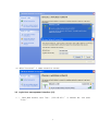
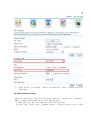
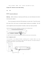
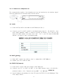
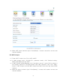
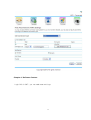
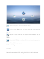
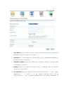
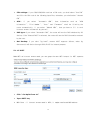
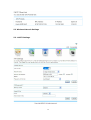
Model: 434T User Manual 02-May-2013 Table of Contents Chapter I Product Introduction..........................................................................................................3 1.1 Product appearance and LED indicators................................................................................................3 Chapter II Product Installation..........................................................................................................4 2.1 Wireless network connection- take Windows Xp for example Power 434T.......................................4 2.2 Login User management Interface (UI)................................................................................................6 2.3 Wi-Fi password modification.................................................................................................................7 2.4 Default factory setting............................................................................................................................9 Chapter III Internet access mode setting ..............................................................................................10 3.13G..........................................................................................................................................................10 3.1.1 Insert the SIM card............................................................................................................................10 3.1.2 Connect to a PC...............................................................................................................................10 3.1.3 Connect to a telephone set...............................................................................................................11 3.2 ADSL ..................................................................................................................................................11 3.3 DHCP(Hotel)..................................................................................................................................11 3.4 STATIC IP(Campus)............................................................................................................................11 3.5 WIFI Hotspot.......................................................................................................................................12 Chapter Ⅴ Software feature ..............................................................................................13 5.1 Internet settings....................................................................................................................................14 5.1.1 WAN .........................................................................................................................................14 5.1.1.1 STATIC Mode................................................................................................................15 5.1.1.2 DHCP Mode...................................................................................................................15 5.1.1.3 PPPOE (ADSL) Mode...................................................................................................16 5.1.1.4 3G Mode........................................................................................................................18 5.1.1.5 WIFI...............................................................................................................................19 5.1.2 LAN..........................................................................................................................................20 5.1.3 Static Routing............................................................................................................................20 5.1.4 DHCP clients.............................................................................................................................21 5.2 Wireless Network Settings...................................................................................................................22 5.2.1 WIFI Settings............................................................................................................................22 5.3 Firewall ...............................................................................................................................................25 5.3.1 Content Filter............................................................................................................................25 5.3.2 Address Filter ...........................................................................................................................26 5.3.3 Virtual Server............................................................................................................................28 5.3.4 System Security........................................................................................................................31 5.3.5 DMZ Settings............................................................................................................................31 5.4 Admin...................................................................................................................................................31 5.4.1 Status ........................................................................................................................................32 5.4.2 Management..............................................................................................................................33 5.4.3 Upload.......................................................................................................................................35 2 5.4.4 Settings......................................................................................................................................36 Chapter V FTP.................................................................................................................................37 5.5 FTP: files download and upload................................................................................................37 ...........................................................................................................................................................37 Chapter I Product Introduction 1.1 Product appearance and LED indicators 3 Chapter II Product Installation 2.1 Wireless network connection- take Windows Xp for example Power 434T (1) Select “wireless network connection” on “Network Connection” property of the 4 computer desktop. See as below,make the In ternet protocol to “ ob ta in IP address automat ica l l y ” . (2) The icon “ ” comes on the r ight bot tom of computer desktop , press r ight but ton of mouse, then se lect “ V iew Avai lab le Wire less Networks ” in the prompt sess ion. Select SSID:3GRouter_xxxx f rom the wire less network connect ion l i s t ,cl ick “connect” button, 5 (3) When“Connected”,i t means connect ion success. 2.2 Login User management Interface (UI) ( 1 ) Open Web browser, input “http : //192.168.169.1 ” in Address bar , and press “ En ter ” . 6 (2) In the following pop-up window input User name: admin;Password: admin, and click “Login”. 2.3 Wi-Fi password modification (1) Connect your PC to 434T via WiFi ,in the WEB browser input :192.168.169.1,c l ick “W IF I ” i con,input password:admin,enter in to WIFI management set t ing 7 (2) Select the encrypt ion mode in “ Security Mode”,and set WIFI key. 8 (3) After set t ing,cl ick “Apply ” but ton,then 434T wi l l restar t ,connect your PC to 434T again. 2.4 Default factory setting When you reset 434T, it will be factory status. default IP : 192.168.169.1 , password : admin, In te rnet access mode: Smart , SSID:3Grouter_xxxx。 ① Power 434T,then 434T star t and blue l ight f lash (3s/ t imes) . ② Press ” WPS ” but ton, unt i l 5—10s ,then re lease,i f status ind icator l ight i s blue 9 f lash( 1s/t imes) ,i t means “ r eset ” success,then 434T wi l l res tar t . Chapter III Internet access mode setting 3.1 3G 3.1.1 Insert the SIM card Warning Before inserting or removing the SIM card, you must disconnect the device from the power adapter. If you are required to enter the PIN code,enter the correct one. If you fail to enter the correct PIN or PUK code, the network-related functions are unavailable. The SIM card is supplied by the service provider. For details, contact your service provider. Insert the card into the slot completely, as shown in the following figure. To remove the card, press the card gently. Now the card will pop up automatically. 3.1.2 Connect to a PC If the indicator of the Ethernet interface connecting with a network cable is on, the connection is successful. The Ethernet cable cannot be longer than 100 meters (328 feet). To achieve better effect, use the shielded cable. 10 3.1.3 Connect to a telephone set The communication quality of the telephone set can be interfered by the wireless signal. Place the telephone set one meter away from the device. 3.2 ADSL (1) Power 434T put ADSL LAN cable into 434T WAN port (No.1). (2) Connect your PC to 434T via WIFI, in the Web browser input IP :192.168.169.1, then input admin password: admin, a sess ion re jected (as below) , th is t ime you can input your ADSL account in fo, then c l ick “ OK ” 。Ps:i f your ISP requ i re bound MAC address, you need to input corresponding MAC. 3.3 DHCP(Hotel) (1) Power 434T, connect the cable in hote l or modem LAN to 434T WAN por t . (2) Connect your PC to 434T v ia WIFI 3.4 STATIC IP(Campus) (1) Power 434T, connect LAN from modem to 434T WAN port. (2) Connect your PC to 434T via WIFI, in the Web browser input: 192.168.169.1, password: admin,c l ick “ Ne twork set t ing—WAN ” ,set WAN mode:STATIC IP (3) Input IP address and gateway info from ISP under the STATIC IP mode Webpage. Then click “Apply” button. 11 (4) When 434T status indicator light is blue(always), it means connection success and internet available. 3.5 WIFI Hotspot (1) Power 434T, connect your PC to 434T via WIFI (2) In Web browser input: 192.168.169.1, password: admin, click “Network settingWAN”,make WAN mode be “WIFI”. (3) In WIFI Hotspot setting Webpage, click “Get Aplist in the air”, select SSID you know. If the wireless network is encryption,please input WIFI password, then click “Apply” button. If WIFI hotspot is bound MAC, please start MAC clone and input bound MAC address. (4) When the status indicator light is blue(always), it means dail number success and internet available. 12 Chapter Ⅴ Software feature Login GUI of 434T,you can make some set t ings. 13 :Check and conf igue the bas ic in fo of wire less network : Login the status Webpage,check the in ternet access mode, connect ion and net f low, ect . :When ADSL i s cur rent access mode,you can input account and password f rom your operator . :When put t ing 3G USB Modem, accord ing to SIM and cur rent network requ i rement you can input PIN and APN f rom your operator 5.1 Internet settings 5.1.1 WAN There are five online methods (STATIC, DHCP, PPPOE (ADSL), 3G. ,WIFI in WAN mode. 14 5.1.1.1 STATIC Mode The superior equipment is router or others; you need to enter fixed IP address provided by ISP. IP address: Static IP address provided the ISP. Subnet mask: Provided by ISP. Default Gateway:Fi l l in the gateway address as prov ided by the ISP. Primary DNS Server:Fi l l in the DNS server as prov ided by the ISP. Dif ferent areas have di f fe rent DNS addresses. Secondary DNS Server : Fi l l in the DNS server as prov ided by the ISP. Dif ferent areas have di f fe rent DNS addresses. 5.1.1.2 DHCP Mode The superior equipment is router; you can acquire IP address from ISP and access internet without filling any content. Obtain IP and DNS information relating to the extranet ports from the DHCP server and make 15 sure that the extranet ports connect to DHCP server. You can choose not to fill in the Hostname. 5.1.1.3 PPPOE (ADSL) Mode Superior equipment is modem or optical fibre; you need to enter user name and password appointed by ISP. 16 User Name: Fill in the Internet access account as provided by the ISP. Please place enquiries on the ISP in case of any queries. Password: Fill in the password as provided by the ISP. Please place enquiries on the ISP in case of any queries. Operation modes: Divided into “Keep Alive” connection, “Manual” connection and “On Demand” connection. Manual : se lcet th is opt ion,you need to dai l no manual ly when the in te rnet connect ion i s shut-down. On Demand: when the network visit is required from LAN , i t wi l l connect automat ica l l y 。 I f there i s no any network requ i red with in set t ing t ime( l e isure) , i t wi l l disconnect automat ica l l y ( no disp lay disconnect in 17 status webpage)。 This mode i s su i tab le for the user who pay accord ing to the in te rnet us ing t ime and save the cost . 5.1.1.4 3G Mode Use 3G wireless data card 3G Run Type: ⑴ 、 Under the “ Keep Al ive ” mode, the router wi l l dia l up automat ica l ly and get connected to the In te rnet when 3G equipment i s plugged in . ⑵ 、 Under the “Manua l ” mode, the access in ternet th rough dia l-up wi l l not be l aunched unt i l the user c l icks “ Connect ion ” on the status page. ⑶ 、 Under the “ On-Demand ” mode, the system wi l l be connected to the network automat ica l ly in case of WAN access requests. I f there are no network access requests with in the speci f ic per iod ( id le t ime), the system wi l l disconnect to the network automat ica l ly . This connect ion mode could ef fect ive ly save network access fees for users that se lect to make payment by the t ime actua l ly consumed. 18 PIN settings: If your SIM/USIM/UIM card has a PIN code, you shall select “Use PIN” and fill in the PIN code in the following Input Box, otherwise, you shall select “Unused PIN”. APN : I f you se lect “ Au tomat ic APN ” , then in format ion such as “ APN In format ion ” , “ D ia l Number ” , “ User ” and “ Password ” sha l l be f i l led by the router automat ica l ly . I f you se lect “Manua l APN ” , then you have to f i l l in such In ternet access in format ion by yourse l f . DNS type: If you select “Automatic DNS”, the router will use the DNS obtained by 3G dial-up. If the “Manual DNS” is selected, the router will use the DNS information entered by the user. Net Backup: If you slect “3g back”, means 434T supports failover, when 3g disconnect,it will dial no through ADSL/DHCP for internet prepare. 5.1.1.5 WIFI Make WIFI as in te rnet access mode, you can grasp the near WIFI hotspot for WIFI repeater . Click “ Get Aplist from air” Input WIFI key MAC Clone :I f in te rnet access mode i s ADSL, i t maybe need bound MAC address 19 5.1.2 LAN IP address: Set up IP addresses for Intranet ports Subnet mask: Set up masks for the Intranet. MAC address: Indicated physical addresses of the Intranet ports. DHCP type: Select “Server” to open DHCP services and then the host in the Intranet could obtain IPs dynamically. Start IP address-End IP address: IPs obtained by the host in the Intranet via DHCP mode is included in this range. 5.1.3 Static Routing This function may be used when it is required to add a specific routing for a certain host. The proper use of static routing could reduce routing issues, alleviate the overload of routing data flows and enhance the transmission speed for the data packets. A routing item may be identified by setting targeted IP address, subnet mask and gateway address, among which the targeted IP address and the subnet mask are used to identify a target network/host. Afterwards, the router transmits the data packets to the designated target network/host via the gateway. 20 Destination IP address: Identify target addresses or networks that are hopefully to be visited. Range : Host/Net: The selection of a host means to designate a certain IP for the host. The network defines a specific network segment by defining a subnet mask. Gateway: IP address of the router or the host where the data packets are sent. Interface: Indicate connector information. Comment: Fill in necessary notes. Current Routing table in the system: Display all kinds of information relating to all current router tables that are defined by the user. 5.1.4 DHCP clients Display information relevant to the hosts that are connected to the router’s Intranet via DHCP. DHCP client list enables you to check the status of online users such as MAC address, IP address and lease periods of the IP address. 21 5.2 Wireless Network Settings 5.2.1 WIFI Settings 22 Wireless switch: Switch on/off wireless functions of the router. Network mode: Wireless application standards for the router. The router supports 802.11b, 802.11g, and 802.11n or mix modes. SSID: Network name of the wireless signals. This router supports multiple wireless networks. If you select “Hidden the Wireless Client”, you cannot scan the router’s SSID. If you select “Isolated”, you can prevent other users under the same network between the transmission of the virus. Broadcast network Name: You can select “Disable” to forbid the router to broadcast SSID. After that, the wireless clients cannot scan the router’s SSID. The clients cannot communicate with the router if they fail to know the router’s SSID. The broadcast network identifier is defaulted as “Enable”. Frequency (channel): Channels currently used by the router. Other effective work channels could be selected from the following list and options are 1 to 13. Security mode:open 、 share 、 WEP、 WPA、 WPA-PSK、 WPA2、 WPA2-PSK、 WPA-PSK /WPA2- PSK 、WPA1WPA2、8021.X 5.2.2 WPS Conf igurat ions Wi-Fi Protect ion Set t ings (WPS) can eas i ly and quick ly estab l ish an encrypted connect ion among cl ients of the wire less network. You have no need to se lect the encrypt ion mode or conf igure a key. You jus t need to press “ WPS ” but ton one second, or enter cor rect PIN code or se lect PBC (or press “WLAN/WPS ” but ton ind icated on the back panel ) to eas i ly conf igure WPS. 23 Wi-Fi Protection Settings: Used to disable or enable WPS functions. The default status is “Disable”. WPS Overview: Display relevant information including current WPS status, authentication modes and encryption types applied, and default private key indexing. WPS Current Status: “Idle” means the idle status. “Start MSC Process” means that the process is enabled and the access is on the way. “Success” means that the server and the client have reached an agreement during the negotiation. WPS Validity: “Yes” means taking effect and “Not Used” means not taking effect. Generally, if the AP-Safety Configuration takes effect, this place will be displayed as “Not Used”. SSID Configured by WPS: Display master SSID numbers of the WPS. WPS is only valid for the master SSID. WPS Authentication Mode: The authentication mode used by WPS. WPA/WPA2-Personal 24 mode is commonly seen. WPS Encryption Type: It means the data encryption type. AES/TKIP encryption type is commonly seen. WPS Key: Effective keys automatically generated by AP. Reset OOB: When you press this button, the WPS service terminal is indicated as Idle and the WPS indication light turns off. AP will not respond to connection requests from WPS clients and the safety are configured as WPA mode. WPS Mode: Support two kinds of simple WPS settings, namely PBC (Push-Button Configuration) and PIN code. PBC: select PBC and click "Save as" or press WLAN / WPS button in the back panel for about one second while activating WPS / PBC to connect in the client port. Operation Process: after clicking the WLAN / WPS button for one second, WPS lights will blink about 2 minutes, indicating that the function is activated. In this time range, the wireless client ports can activate the WPS / PBC for authentication and consultation. After the connection is successfully connected, WPS indication light will be off and access process of wireless client could be completed. If users want to access multiple wireless client ports, users need to repeat the process. It could support up to 32 wireless client ports to access. PIN: If users want to use the PIN, users must know the PIN code of wireless client ports. Users could just add to the input box and then save while using the same PIN code to make connection in the client ports. PIN (Key): Default PIN code. 5.3 Firewall 5.3.1 Content Filter Webpage content filtering: Filter the part “Proxy Java ActiveX” of the web pages. URL filtering: Filter out the entire content of the webpage of URL 25 Web host filtering: URL WEBPAGES including keywords are filtered. 5.3.2 Address Filter This function is aimed at restricting and managing the client ports of the router. If you need to limit Internet use of the machine of the router, you could use this function. To use this function, you should first activate it and then select a default strategy (accept or reject), which means the data packets that do not comply with the rules to be accepted or rejected. And then fill out the corresponding filter rules. Pay attention that it is not required you to fill out all the items but to fill the appropriate selection according your own requirements. For example, to ban the IP of 192.168.1.146 to use Internet (others can use Internet), you just need to adopt the default strategy as acceptance strategy and fill 192.168.1.146 in the column of the source IP address. To use this function could enhance users’ security and manageability of LAN. 26 Mac/IP/Port Filtering: This function takes no effect if “Prohibit” is selected. After you click “Enable”, this function will take effect. Default Policy: Select “Dropped” or “Accepted”. This strategy shall be implemented if rules as defined below are not matched. MAC Address: Fill in MAC addresses that you plan to define rules. Source IP Address: Enter local IP address that needs filtering. You shall fill in rules that correspond to this IP. 27 Destination IP Address: Enter destination IP address that needs filtering. You shall fill in rules that correspond to this IP. Port range: Ranges for ports that need to be abandoned or accepted. Protocol: Select protocols that are used by controllable data packets. Strategy: Identify whether the defined rules are “Abandon” or “Accept”. It is in the opposite side of the default strategy. Remarks: Indicate the rules defined by you to differentiate such rules. 5.3.3 Virtual Server The virtual host enables remote users who gain access to web or FTP services via public network IP addresses to automatically shift to local servers of the LAN. The virtual server can define a service port. All service requests to such port raised by the Extranet shall be transmitted to LAN servers as specified by the router (based on IP address). This way, the user could successfully access LAN servers without exerting any influences on the internal network safety of the LAN. 28 29 Virtual Server settings: Enable or disable functions of the virtual servers. IP address: It is used to input necessary IP addresses, such as192.168.1.103. Port Range: It is used to input necessary port ranges, such as 80-80. Protocol: Select protocols that are used by controllable data packets. Remarks: Fill in necessary notes. In terms of the configurations described above, all data will be transmitted to a computer with the IP address of 192.168.1.103 within the LAN if some program accesses the 80 port of the router. Current Virtual Servers in system: Indicate the list of current virtual servers. 30 5.3.4 System Security Remote management: Identify whether it is permitted to access WEB management pages via Extranet ports. Ping form WALL Filter: Identify whether it is permitted to PING the router via Extranet port 5.3.5 DMZ Settings Transfer all data that are received by the router’s Extranet ports to “DMZ IP Address” 5.4 Admin 31 5.4.1 Status Current work conditions of the router. System information: Version: indicates the router’s current software versions and the release date. Running Time: indicates the system operation time after the router is loaded with a power supply. Such time will be cleared to zero after the power supply is unloaded. Internet Configurations: Connected : 3G mode conta ins two but tons, namely “ D isconnect ” and “ Connect ” wi l l be disp layed on the in te r face to disconnect and connect the 3G network. Network Mode : Signa l in tens i ty of the 3G network / s igna l in tens i ty of the 2G network. Network type:Which network i s cur rent ly connected(WCDMA,TD,EVDO) WAN IP Address: current WAN IP address of the router. The router’s connection type 3G not connected to the extranet, the address will be displayed as empty or 0.0.0.0. Subnet Mask: Router’s WAN subnet mask. Default Gateway: Router’s WAN default gateway. 32 Primary Domain Name server: Address of the DNS server that is currently used by the router. Local Network: Local IP address: IP address of the router’s Intranet ports. Local Net mask: Subnet mask of the router’s Intranet. MAC address: Physical address of the router’s Intranet ports. 5.4.2 Management Administrator Settings Administrator Settings : Set account and password for admin is t ra tor . You can do any operat ion i f you log in the page in the capaci ty of admin is t ra tor . NTP Settings 33 Current Time:Set the router t ime the same to PC. Time Zone:Select t ime and area. NTP Server: Enter the address for the NTP Server, then the Router will get the time from the NTP Server preferentially. In addition, the router built-in some common NTP Servers, so it can get time automatically once it connects the Internet. NTP Synchronization : In terva ls for the router to obta in data f rom the t ime server . DDNS DDNS (Dynamic Domain Name System) – The capability of assigning a fixed host and domain name to a dynamic Internet IP Address. The router offers the DDNS feature, which allows the hosting of a website, FTP server, or e-mail server with a fixed domain name(named by yourself) and a dynamic IP address, and the your friends can connect to your server by entering your domain name no matter what your IP address is. Before using this feature, you need to sign up for DDNS service providers. The Dynamic DNS client service provider will give you a password or key. Dynamic DNS Provider: select websites that provide dynamic domain name service. 34 Account : the login name you register in the websites that provide dynamic domain name service. Password: the password you register in the websites that provide dynamic domain name service. DDNS: the domain name you register in the websites that provide dynamic domain name service Note: Before using Dynamic Domain Name function, please register the dynamic DNS address services in the website listed in drop-down box of service providers and ensure that this account is effective. 5.4.3 Upload If it is required to upgrade the router’s software, the first choice is to obtain our upgrade files and save it in this equipment. Then click “Browse” in the “Location Update” to select upgrade files, then click “Apply” and keep waiting until the upgrade is done (generally within one minute). 35 5.4.4 Settings Export system configurations: Save system configuration files locally for further recoveries. Export LOG: Click the “open” button; store the Log file locally to seek error. Import system configurations: Introduce local configuration files to the router. After that, each configuration of the router will be updated into the configuration files. Load Factory Defaults: All the configurations will reset to the factory original settings Clear Flux Defaults: Click “Clear Flux”, current flux and amass flux of the main page will be cleared 36 Chapter V FTP 5.5 FTP: files download and upload Put USB driver/Hard disk/HDD into USB port of 434T, then connect your PC to 434T via WIFI or cable. Click your “My computer” or “Browser”, input:ftp://192.168.169.1. then you can see all files and you can upload and download the files you want. 37