1
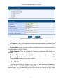
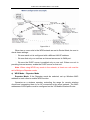
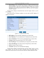
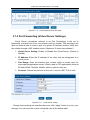
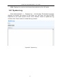
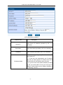
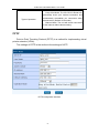
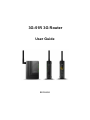
3G-51R 3G Router
User Guide
2011-5-10
3G Wireless-N Broadband Router’s User Guide
Contents
CHAPTER 1 ...........................................................................................................................................1
1.1 INTRODUCTION ...............................................................................................................................1
1.2 OVERVIEW......................................................................................................................................1
1.2.1 Product Appearance............................................................................................................1
1.2.2 Physical Details....................................................................................................................2
1.2.2.1 Front Panel........................................................................................................................2
1.2.2.2 Rear Panel ........................................................................................................................3
1.3 FEATURE ........................................................................................................................................3
CHAPTER 2 CLIENT CONFIGURATION .......................................................................................6
2.1 SUMMARY.......................................................................................................................................6
2.2 COMPUTER CONFIGURATION .........................................................................................................6
2.2.1 System Requirement...........................................................................................................6
2.2.2 Connection Type ..................................................................................................................6
2.2.3 Network Configuration ........................................................................................................7
2.2.4 Test of the network connection. .......................................................................................10
CHAPTER 3 SOFTWARE CONFIGURATION ...............................................................................12
3.1 SUMMARY...................................................................................................................................12
3.2 LOGIN .........................................................................................................................................12
3.3 ISP CONFIGURATION .................................................................................................................14
3.4 NETWORK CONFIGURATION.........................................................................................................14
3.4.1 LAN Setting ........................................................................................................................14
3.4.2 WAN Setting .......................................................................................................................16
3.4.3 MAC Clone .........................................................................................................................21
3.4.4 Advanced Routing .............................................................................................................22
3.5 W IRELESS SETTINGS ...................................................................................................................24
3.5.1 Basic Setting ......................................................................................................................24
3.5.2 Advanced Setting...............................................................................................................27
3.5.3 Security ...............................................................................................................................30
3.5.4 WDS ....................................................................................................................................37
3.5.5 WPS.....................................................................................................................................41
3.5.6 Station List ..........................................................................................................................43
3.6
DHCP SERVER ........................................................................................................................44
3.6.1 DHCP Server Setting ........................................................................................................44
3.6.2 DHCP Clients .....................................................................................................................46
3.7 FIREWALL .....................................................................................................................................46
3.7.1 MAC/IP/Port Filtering. .......................................................................................................46
3G Wireless-N Broadband Router’s User Guide
3.7.2 Port Forwarding (Virtual Server Settings) ......................................................................48
3.7.3 DMZ .....................................................................................................................................49
3.7.4 System Security .................................................................................................................50
3.7.5 Content Filtering. ...............................................................................................................51
3.8 ADMINISTRATION ........................................................................................................................52
3.8.1 Operation Mode .................................................................................................................53
3.8.2 Management ......................................................................................................................54
3.8.3 Upgrade Firmware.............................................................................................................55
3.8.4 Settings Management .......................................................................................................56
3.8.5 Status...................................................................................................................................57
3.8.6 Statistic ................................................................................................................................59
3.8.7 System Log.........................................................................................................................60
APPENDIX ...........................................................................................................................................61
WAN SETTING ....................................................................................................................................61
PPPoE (ADSL)...............................................................................................................................61
L2TP...............................................................................................................................................62
PPTP ..............................................................................................................................................64
COMMON APN SETTINGS ....................................................................................................................65
3G Wireless-N Broadband Router’s User Guide
Chapter 1
1.1 Introduction
Thank you for purchasing the 3G-51R 3G Router. The 51R 3G-51R 150M
Router supports WiFi, Ethernet gateway and 3G in one device and is especially
designed for the small enterprise, office and family users. It offers wireless
broadband WAN HSUPA connection with rate up to 7.2Mbps. On Local area
Network (LAN), it supports both the newest IEEE802.11n and the older
IEEE802.11b/g and wire Ethernet 10/100Mbps interfaces. It supports TD-SCDMA,
CDMA2000/EVDO and WCDMA 3G network.
The 3G-51R integrates a WAN port, a 10/100Mbps LAN port and a SIM slot for
directly using the 3G data SIM - no USB dongle required! The 11n WiFi supports
rates up to 150Mbps with a NAT firewall which supports SPI and an easy-to–use
web operation interface.
1.2 Overview
1.2.1 Product Appearance
Figure1.2.1 3G-51R appearance picture
1
3G Wireless-N Broadband Router’s User Guide
1.2.2 Physical Details
1.2.2.1 Front Panel
The router front panel has indicator lights with the following layout.
Figure1.2.2 the front panel picture
Name
State
Light on
Description
The power is ready and it works
Power
Light off
The power is off.
The connection is established with the computer or the local
Light on
area network through the corresponding LAN port.
LAN
Light flash
Light off
Sending / receiving data
There is no device linked to the corresponding LAN port
The connection is established with the xDSL Modem/Cable
Light on
through the corresponding WAN port.
WAN
Light flash
WiFi
3G
Modem or Ethernet (for example: Hub, Switch and Router)
Sending/receiving data
Light off
There is no device linked to the corresponding WAN port
Light on
The wireless connection is established
Light flash
Sending /receiving data
Light off
The wireless connection is not established
Light on
The 3G service is ready.
Light flash
Light off
Trying to link the 3G network..
The 3G service is not established.
2
3G Wireless-N Broadband Router’s User Guide
1.2.2.2 Rear Panel
The most ports of 3G-51R are put on the rear panel, please see the following
picture:
Figure 1.2.1 the rear panel picture
3G ANT
3G/WiFi antenna port, used for 3G/WiFi wireless operation
and data transmit.
WAN
Wide area Network port (RJ45). It is used for connecting the
router to the xDSL Modem/ Cable Modem or Ethernet network
device(for example :Hub, Switch and Router)
LAN
Local area Network port (RJ45) . Through this port, you can
connect the router to your PCs and other Ethernet network
device (for example: Hub, Switch).
SIM Card
SIM card port
Power
Turning on/off the router power.
Reset
After the router is power on, press this reset button for five
seconds to reset the router, the router will be restored to
factory default settings.
DC(+9V)
The power plug is where you connect the power adaptor.
Note: Please use the power adaptor which attached for the
router, for preventing from the router damage.
1.3 Feature
Conforms to the IEEE 802.11g、IEEE 802.11b、IEEE802.11n draft v2.0
standard
Supports CSMA/CA、CSMA/CD、TCP/IP、PPPoE、DHCP、ICMP、NAT
protocol
10/100M Ethernet network(WAN) port to connect with ADSL or Ethernet
network device(for example : Switch / Router).
Built in 3G modem – takes SIM directly. No need to use 3G wireless USB Adaptor.
Uses Sierra MC8785 3G modem.
3
3G Wireless-N Broadband Router’s User Guide
LAn/WAN ports automatically detect MDI or MDIX
WiFi supports 64/128 WEP and also WPA, WPA2, IEEE802.11i and TKIP
encryption.
SSID broadcast control and access control based on MAC.
WDS wireless repeater mode
Built-in DHCP server
Built-in SPI NAT firewall, support PING ,Broadcast and the content of
packet, MAC address, IP address, URL and Domain name filtering
Supports static route setting
Supports VPN (PPTP/IPSec/L2TP) pass-through
Supports virtual server and DMZ
Supports UPnP, DNS PROXY
Supports MAC address revised and cloned
Built-in TD-SCDMA / WCDMA / EVDO 3G wireless modem.
3G wireless network autodial, reconnection and route.
Remote web management
1.4 Software Feature
1
2
3
Internet connection, build connection with Virtual Private Network
including PPTP,L2TP and so on through WAN port.
Support PPPoE dialing and build link with separate xDSL broadband
connection through WAN port.
Support static IP address setting and connect to the special net through
WAN port.
4
Support DHCP Client linking.
5
Supply WAN port MAC address cloned
6
Support PPP Dialing through built-in 3G module, and make connect to
3G mobile network
8
Support manual or automatic option for turn on/off 3G connection,
9
Support auto-reconnect when PPP disconnection
10
11
Support AP client, Ethernet to WiFi converter mode so that
machine can join to one 802.11b/g/n AP network.
Supply WEP、WPA-TKIP、WPA-AES、WPA-TKIP+AES、WPA2-TKIP、
WPA2- AES、WPA2-TKIP+AES wireless encryption, and support SSID
broadcast control .
4
3G Wireless-N Broadband Router’s User Guide
12
Show WAN port, LAN port, WiFi and 3G network port status.
13
Support IP address and subnet management of LAN port.
14
Support DHCP service management of LAN port.
15
Support NAT firewall setting
16
Support data packet relay and static route management
17
Support management of appending and deleting static route rule
18
Support DMZ,make the machine can communicate each other whether
location on internet or intranet.
19
Support IP address ,MAC address ,port and packet filtering
20
Enable/Disable WEB remote management
21
Set router time
5
3G Wireless-N Broadband Router’s User Guide
Chapter 2 Client Configuration
2.1 Summary
Before using the Wireless-N Router, you need ensure your computer network is
configured to talk to the router.
2.2 Computer Configuration
2.2.1 System Requirement
When you setup the 3G-51R 3G Router, you will need a computer with a
network LAN port which supports TCP/IP protocol and a web browser e.g. Microsoft
internet Explore.
2.2.2 Connection Type
There are two ways to connect your configuration computer to the 3G-51R 3G
Router.
2.2.2.1 Connect the router by the Ethernet directly
Connect the Router’s LAN port to your network card by cable as shown below:
Figure2.2.1
2.2.2.2 Local area Network connection type
Connect the 3G-51R 3G Router to your Local area Network via switch or hub:
6
3G Wireless-N Broadband Router’s User Guide
Figure 2.2.2
2.2.3 Network Configuration
After connecting the router to your LAN you need set your computer IP address
and other parameters to match the router.
The following is the detail of network setting, take Windows XP for example:
⒈ Double click the “Start” menu, then select “Control panel”, one icon
“Network and internet Connections” pop-up, double click it, then select the
“Local Area Connection”. See the following figure for reference:
7
3G Wireless-N Broadband Router’s User Guide
Figure2.3 LAN Area Connection configuration
⒉ Double click “Local Area Connection”, then popup a dialog box, select
“Properties”, then select “Internet Protocol (TCP/IP), click “Properties
(R) ” ,see the following figure:
Figure 2.4 Local Area Connection properties configure
⒊We can choose two setting-up type in the interface “Internet protocol
(TCP/IP) Properties”
One: Select “obtain an IP address automatically” and “obtain DNS server
address automatically”, see the following figure
8
3G Wireless-N Broadband Router’s User Guide
Figure 2.5 Internet Protocol (TCP/IP) properties setting
Click the “OK” button, the local computer will request assigning IP address and
DNS automatically.
Note: The router default to enable DHCP server, it will assign an IP address to
the computer of the local area network automatically.
Two: Set up fixed IP address, select “Use the following IP address” and “Use
the following DNS server address”, then fill in the following parameter.
IP address:192.168.0.x (x is a integer between 100-200)
Subnet mask code:255.255.255.0;
Tacit gateway:192.168.0.1;
DNS Server:
:You can fill in your local DNS server address provided by your ISP,
or you can take the router as DNS proxy server.
9
3G Wireless-N Broadband Router’s User Guide
Figure2.6 configure IP address and DNS manually
Click the “OK” button. The above settings is submitted, then the interface turn
to “Local Area Connection Properties”, Click the “OK” button to save the above
settings.
Tip: If you are not sure of the DNS server address, we recommend you to
select “Obtain an IP address automatically (O)” and “Obtain a DNS server address
automatically”.
Note:The following is the factory default setting parameter of 3G-51R 3G Router
LAN port:
IP address:192.168.0.1
Subnet mask code:255.255.255.0
2.2.4 Test of the network connection.
The first step:Checking the IP configuration
After setting up TCP/IP, you can use the order “ipconfig” to check if the IP is
assigned.
10
3G Wireless-N Broadband Router’s User Guide
Click “Start”→ “Run”→ Input “cmd”, then input the order “ipconfig” and hit
“enter” key.
Make sure that the user’s network configuration conforms to the following three
requirements:
① IP address must be between: 192.168.0.100 to 192.168.0.200
② Subnet mask code is 255.255.255.0
③ Default gateway is 192.168.0.1
For example,the right configuration information of system feedback is the
following information:
Ethernet adapter Local Area Connection:
Connection-specific DNS Suffix :
IP Address. . . . . . . . . . . . : 192.168.0.100
Subnet Mask . . . . . . . . . . . : 255.255.255.0
Default Gateway . . . . . . . . . : 192.168.0.1
The second step: Test of connectivity
After finish computer configuration, you use the command “Ping” to check the
connected situation between the computer and the router. Click “Begin”→ “Run”,
then input command line “CMD”, then input the command “Ping 192.168.0.1”,and
hit “Enter”. If the screen output the following information, it means the normal
connection has established from computer to the router.
Pinging 192.168.0.1 with 32 bytes of data:
Reply from 192.168.0.1: bytes=32 time=1ms TTL=64
Reply from 192.168.0.1: bytes=32 time=1ms TTL=64
Reply from 192.168.0.1: bytes=32 time=1ms TTL=64
Reply from 192.168.0.1: bytes=32 time<1ms TTL=64
Ping statistics for 192.168.0.1:
Packets: Sent = 4, Received = 4, Lost = 0 (0% loss),
Approximate round trip times in milliseconds:
Minimum = 0ms, Maximum = 1ms, Average = 0ms
You can do some configuration on the 3G-51R broadband Router.
If the screen appears the following information, it shows the equipment hasn’t
installed:
Pinging 192.168.0.1 with 32 bytes of data:
Request timed out
Request timed out
Request timed out
11
3G Wireless-N Broadband Router’s User Guide
Request timed out
This information show the equipment is not ready, You can check it according
to the following sequence:
1.Hardware connection:The both LAN port LED indicator on the router’s rear
panel and the one on the computer network card are bright。
2.Computer TCP/IP attribute configuration: If the router LAN IP address is
192.168.0.1 , the computer IP address should be one address value range from
192.168.0.100 to192.168.0.200
Chapter 3 Software Configuration
3.1 Summary
The 3G-51R 3G Router uses web-based configuration, management and
debugging interface, you must configure the relevant parameter according to the
local network environment before using the 3G-51R 3G Router.
3.2 Login
⒈ Open your browser, input the IP address of your router, which by default is
192.168.0.1
Figure 3.2-1
⒉ One user name and password window prompt appears. Input the user
name and password, and chick “OK”:
12
3G Wireless-N Broadband Router’s User Guide
Figure 3.2-1 Login interface
Note:The initialization user name and password are admin, you can change the user
password when you enter system.
⒊ After your successful login, you enter the 3G-51R 3G Router WEB
configuration interface. See the following picture:
13
3G Wireless-N Broadband Router’s User Guide
Figure 3.2-2 Web configuration main interface
The main menus are on the left of the web-based utility. Submenus will show after
you click one of the main menus. On the right of the web-based page, there are
detailed explanation and instructions for the corresponding page. To apply any
settings you have altered on the page, please click the save button.
3.3 ISP Configuration
3G-51R 3G Router support the following six common WAN connection types (default
connection type is dynamic IP address connection via cable).
Dynamic IP Address: Broadband network or cable connection, assign IP
address through DHCP service from ISP.
Static IP Address: It is a static mode and Ethernet connecting, static IP
address assign from ISP.
PPPoE dialing:
: Link with internet through PPPoE;
L2TP:
:Link with internet through virtual private network dialing.
PPTP:
:Support multi –protocol dummy special network.
3G:
:Wireless linking with Internet, support USB 3G modem and internal PCI-E
3G module.
In the UK the only two connection types applicable are dynamic/static IP
via the WAN port (connecting to an existing internet router) or 3G. For
simplicity the other connection modes are covered in the Appendix at the end
of the manual.
3.4 Network Configuration
3.4.1 LAN Setting
Click the "Primary" button to the page, you can set up the configuration of LAN
interface.
14
3G Wireless-N Broadband Router’s User Guide
Figure 3.4.1 Primary setting
The following options are displayed on this page:
option
Description
IP address
Shows the IP address of the Wireless-N Router’s
LAN port. Default IP address is 192.168.0.1, user
can change it
Subnet mask
Subnet Mask of router’s LAN IP address. Default
subnet mask is 255.255.255.0
MAC Address
The physical layer address for the Wireless-N
Router’s LAN port.
DNS Proxy
Start DNS Proxy on the firewall feature, the default:
disable.
Note:After finishing the setting, click Apply to save the settings. When you change the IP
address of LAN port, please login in the WEB configuration interface with the router’s new IP
address.
All devices on the network must have the same subnet mask to communicate on the
network.
15
3G Wireless-N Broadband Router’s User Guide
3.4.2 WAN Setting
Click "Internet Settings" - > "WAN" and enter into the WAN setting page,
It shows the six mode for the Wireless-N Router’s WAN port configuration, please
choose the proper connection mode for you, and then fill in your connected
parameter.
Figure 3.4.2-2 WAN configuration interface
3.4.2.1 DHCP (Auto Config)
Select DHCP (Auto Config) for the WAN port. This setting allows the
Wireless-N Router to automatically obtain an IP address from a DHCP server
normally via a separate DSL or broadband router. This access mode does not
require you to do special settings.
In the following picture 3.5, the “optional” means the hostname of the DHCP
16
3G Wireless-N Broadband Router’s User Guide
client on the network.
Figure 3.4.2-3 DHCP configuration interface
3.4.2.2 Static IP(
(fixed IP)
)
Select STATIC (fixed IP) for the WAN port. Then fill the IP address、subnet
mask、default Gateway、primary DNS server and secondary DNS server (you can
get parameters from your ISP, and you must enter and fill in at least one
parameter).
Note: The IP address of LAN port and WAN port can not be set to the same
sub network.
17
3G Wireless-N Broadband Router’s User Guide
Figure 3.4.2-4 Fixed IP configuration interface
You should input the following parameters into the blank provided:
IP Address: Enter the IP address in dotted-decimal notation provided by your
ISP.
Subnet Mask: Enter the subnet Mask in dotted-decimal notation provided by
your ISP usually is 255.255.255.0
WAN Gateway: Enter the gateway IP address in dotted-decimal notation by
your ISP.
Primary DNS: The DNS should be set to the address provided by your ISP.
Secondary DNS: The DNS should be set to the address provided by your ISP.
Click the Apply button to save your settings.
3.4.2.6 3G
The Wireless-N Router support three type of 3G broadband connection:
WCDMA, CDMA 2000/EVDO & TD-SCDMA. With the router power off, you first
need to insert your 3G data SIM into the SIM slot on the front of the unit. Then
power the router back up again.
18
3G Wireless-N Broadband Router’s User Guide
Figure 3.4.2-8 3G configuration interface
Parameter Item
Description
USB 3G modem
This should be left as Auto Detect.
Connect Status
The current status of the 3G network connection
Boot-up dial mode: auto & manual.
Dial Setting
Dial parameter: Default & User defined.
User
Enter the correct User Name provided by your ISP.
Only required if specified by ISP. There is a list of
common settings for UK providers in the Appendix
however this is not definitive and you may need to
19
3G Wireless-N Broadband Router’s User Guide
ask your ISP for this information.
Password
Enter the correct Password provided by your ISP –
see Appendix if not sure.
Dial Number
Enter the correct Dial Number provide by your ISP.
Only required if specified by ISP. All UK Providors
use *99# for this string.
APN
Input the correct APN (Access Point Name) provide
by your ISP – see Appendix if not sure.
Authentication
For the UK this parameter should be set to NO
AUTH.
If required you can also set this to PAP of CHAP.
PIN
Personal Identification Number for SIM.
Only required if specified by ISP.
Please enter the 3G dial parameters required for your account then Click the
Apply button to save your setting.
If you need make 3G online, click on "Connect" button.
Note:
1.
It requires about half one minute for 3G dial-up time, if the dial-up is unsuccessful,
check your settings and/or signal strength.
2.
After 3G connection is successful, the connection via Ethernet or WiFi (between
your computer and the Wireless-N Router) will automatically disconnect and then
reconnect to get the revised DNS setting from the 3G connection.
Keep Alive parameters
Parameter Item
Description
20
3G Wireless-N Broadband Router’s User Guide
LCP
DNS Resolve
PPP parameter link protocol
Enter Domain Name System (DNS) Server.
Destination IP Address: Enter target IP address which you
need ping to periodically
Ping
Using Gate way IP Address: Select this option, Using Gate
way IP Address as Destination IP Address for ping.)
String : The content of heartbeat packet which send to
destination machine
Destination IP Address: IP address of destination machine
which receive heartbeat packet
Heartbeat
Protocol: heartbeat packet sending protocol, you can
choose UDP or TCP
Port Number:port number of destination machine which
receive heartbeat packet
Interval: redial-up interval (unit is second)
Retry Number: Retry Dial-up times
Operation Mode
When the 3G network is off-line abnormality, the router will
execute this redial policy, router will Ping the IP Address
periodically according to the “interval” value, and redial once
failed time of PING over the number of “Retry Number”
value.
3.4.3 MAC Clone
Chick “Internet Settings --> MAC Clone”, you may enable/disable WAN
Interface MAC Clone functions as your wish.
Some ISP require you binding MAC Address with the computer in order to stop
multi-computer share bandwidth. You can fill one valid MAC on the router so that
you can share the bandwidth to multi-computers disregard for one MAC for one
computer rule.
MAC Address:
:The IP Address of the router’s WAN port.
Fill MAC Address: Config the physical address for the router’s WAN port.
21
3G Wireless-N Broadband Router’s User Guide
Figure 3.4.3 MAC clone interface
Notes: Only LAN in the computer can not use the "MAC address copy" function.
Only the PC for the LAN port can “MAC address clone”
3.4.4 Advanced Routing
Chick “Internet Settings --> Advanced Routing” to the page.
Routing setup allows a manual method to set up routing between networks.
The network administrator configures static routes by entering routes directly into
the routing table. Static routing has the advantage of being predictable and easy to
configure.
Static Routing is a specially routing, you need finish configuration manually. In
the network communication, we can improve communication efficiency and promote
packet transfer speed after use suitable routing rule.
This screen is used to manually configure static routes to other IP networks,
sub networks, or hosts. Click “Network Settings” followed by “Advanced Routing.”
(Maximum 32 entries are allowed).
Enter the IP address, enable the static routing.
22
3G Wireless-N Broadband Router’s User Guide
Figure 3.4.4-1 Add new routing rule
The following items are displayed on this page:
Destination: The network address of the destination LAN segment. When
a packet with destination IP address that matches to this field, it will route to
the device set in the Route Gateway field.
Range: Defines the type of destination. (Options: Host/Net, Default: Host)
Net mask: Enter the Net mask, general as 255.255.255.0.
Gateway: Enter the Gateway IP address in the field.
Interface: The selected interface to which a static routing subnet is to be
applied.
Comment: Enter note or remark here.
Note:
1.
Destination can not be the same as WAN or LAN port.
2.
The sub-net of gateway must be the same as WAN or LAN port.
3.
If the destination is a host‘s address, the Net mask must be
255.255.255.255
4.
If the destination for IP network segment is the same, it is
matching with the Net mask.
This table displays the information necessary to forward a packet along the
best path toward its destination. Each packet contains information about its origin
and destination. When a packet is received, a network device examines the packet
and matches it to the routing table entry providing the best match for its destination.
The table then provides the device with instructions for sending the packet to the
next hop on its route across the network.
Figure 3.4.4-2 Current Routing table in the system
Destination: Displays all destination networks or specific hosts to which packets can be
routed.
23
3G Wireless-N Broadband Router’s User Guide
Netmask: Displays the sub network associated with the destination.
Gateway: Displays the IP address of the router at the next hop to which matching frames
are forwarded.
Flags: Possible flags identify as below
0: reject route
1: route is up
3: route is up, use gateway
5: route is up, target is a host
7: route is up, use gateway, target is a host
Metric: A number used to indicate the cost of the route so that the best route, among
potentially multiple routes to the same destination, can be selected.
3.5 Wireless Settings
3.5.1 Basic Setting
Chick “Wireless Settings” --> “Basic” to the configure page. You can setup the
basic setting of wireless, such as “turn on/off radio”, “SSID” ,work channel and etc.
After “turn on radio”, router’s wireless AP service function will be start, so
wireless terminal device can access this router.
But the setting of wireless is not safety now, you should do some configuration
for keep communication environment safety.
24
3G Wireless-N Broadband Router’s User Guide
Figure 3.5.1 Wireless basic setting
Please check these options for basic setting:
Radio On/Off:Click the button to turn on/off the wireless function.
Network Mode:
:Select the wireless network mode from the pull-down list.
Default is 11b/g/n mixed mode.
11b/g mode: Allow the 11b/g-compliant client device to connect with
the AP with auto-negotiation speed, and 11n wireless client to
connect the device with 11g speed.
11b mode:Allow the wireless client to connect with the device in 11b
mode at the maximum speed of 11Mbps.
11g mode:Allow the 11g/11n-compliant client device to connect with
the AP at the maximum speed of 54Mbps.
11b/g/n mode:Allow 11b/g/n-compliant client device to connect with
the AP with auto-negotiation speed.
Rate:Select the wireless network rate from the pull-down list. Default is
Auto.
25
3G Wireless-N Broadband Router’s User Guide
Network Name(SSID)
): The SSID is the unique name of a wireless access
point (AP) used to distinguish one from another. It can be modify.
Note:It is case sensitive and can be up to 32 characters.
Broadcast Network Name (SSID):
:It is used to broadcast its SSID on the
network so that when a wireless client searches for a network, the device can be
discovered and recognized. Default setting is “Disable”.
Enable: When enabled, the SSID is broadcast for wireless users to use.
Disable: When disabled, prevents the SSID broadcast from being seen by
wireless users.
AP Isolation:the AP in isolation,after the commissioning of the AP within
the client can visit each other, can prevent the spread of the virus.
MBSSID AP Isolation:
:the AP out isolation,Enable or disable the isolation
among different SSIDs. After enabling this function, the client terminals with
different SSIDs can not communicate each other.
BSSID:The MAC address of the wireless interface.
Frequency (Channel):
:Select the wireless channel ID from 1 to 14 that you
would like to use.
When Band Mode select in 802.11a/n mixed mode, the HT(High Throughput)
settings should be shown-up immediately.
HT TxStream/RxStream: Select 1 or 2 from the drop-down list:
26
3G Wireless-N Broadband Router’s User Guide
Operating Mode :
1) Mixed Mode: In this mode packets are transmitted with a preamble
compatible with the legacy 802.11a/g, the rest of the packet has a new
format. In this mode the receiver shall be able to decode both the Mixed
Mode packets and legacy packets.
2) Green Field: In this mode high throughput packets are transmitted without
a legacy compatible part. User Manual
Channel Bandwidth : The "20/40” MHz option is usually best. The other
option is available for special circumstances.
Guard Interval : Using “Auto” option can increase throughput. However, it
can also increase error rate in some installations, due to increased sensitivity to
radio-frequency reflections. Select the option that works best for your
installation.
MCS: This parameter represents transmission rate. By default (Auto) the fastest
possible transmission rate will be selected. You have the option of selecting the
speed if necessary.
Reverse Direction Grant (RDG) : Disable or enable reserve direction grant.
Default is enabled.
Extension Channel : When “20/40” channel bandwidth has been chosen,
you should select extension channel to get higher throughput.
A-MSDU : Aggregated Mac Service Data Unit. Select Enable to allow
aggregation for multiple MSDUs in one MPDU Default is disabled.
Auto Block ACK : Disable or enable auto block ACK. Default is enabled.
Decline BA Request : Disable or enable decline BA request. Default is
disabled.
3.5.2 Advanced Setting
Click "wireless network Settings" - > "advanced Settings" into the setting page,
on this page, you may configure advanced wireless parameters, such as BG
27
3G Wireless-N Broadband Router’s User Guide
Protection Mode, Data Beacon Rate, data beacon rate, and TX power.
Note: The advanced wireless setting is only for advanced user. For the
common user, do not change any setting on this page.
Figure 3.5.2 Advanced wireless setting
BG Protection Mode:
:Some 802.11g wireless adapters support 802.11g
protections, which allows the adapter search for 802.11b/g singles only.
Select “Auto” to turns it on or off automatically, select “On” to support
protection or select “Off” to disable this function.
Beacon Interval:
:The rate at which beacon signals are transmitted from
the access point. The beacon signals allow wireless clients to maintain
contact with the access point. They may also carry power management
information. The interval time range is the between 20ms and 999ms for
each beacon transmission. The default value is 100ms.
Data Beacon Rate (DTIM): A DTIM is a countdown informing clients of the
next window for listening to broadcast and multicast messages. The DTM
range is between 1ms and 255ms. The default value is 1ms.
Fragment Threshold:
:The value specifies the maximum size of packet
allowed before data is fragmented into multiple packets. Please use this
value to tune the wireless connection if lots of retransmission happens.
Enter a value ranging from 256 to 2346.
RTS Threshold:
:The RTS threshold determines the packet size at which
28
3G Wireless-N Broadband Router’s User Guide
the radio issues a request to send (RTS) before sending the packet. A low
RTS Threshold setting can be useful in areas where many client devices
are associating with the device, or in areas where the clients are far apart
and can detect only the device and not each other. You can enter a setting
ranging from 0 to 2347 bytes.
Short Preamble:
:The short preamble provides 56-bit Synchronization field
to improve WLAN transmission efficiency. Check Enable button for using
Short Preamble, and Disable for using the Long Preamble, 128-bit
Synchronization field, option.
Short Slot:
:For a WLAN network with 802.11g/n devices, the time slot can
be set short to increase the throughput. Disable this option for the
backward compatibility with 802.11b device.
Tx Burst:
: The default TX power is 100%. In case of shortening the
distance and the coverage of the wireless network, input a smaller value to
reduce the radio transmission power. For example, input 80 to apply 80%
TX power.
Pkt_Aggregate:
:Increase efficiency by aggregating multiple packets of
application data into a single transmission frame. In this way, 802.11n
networks can send multiple data packets with the fixed overhead cost of
just a single frame.
IEEE 802.11H Support: Only in applicable for 11a device (which this isn’t!).
Select Enable to enable DFS (Dynamic Frequency Selection). Default is
Enable. When a DFS-enabled radio is operating on one of the following
channels, the wireless device uses DFS to monitor the operating frequency
and switch to another frequency or reduce power as necessary:
DFS Channels 52, 56, 60, 64, 100, 104, 108, 112, 116, 120, 124, 128, 136, 140
The maximum legal transmit power is greater for some 5 GHz channels
than for others. When the wireless device randomly selects a 5 GHz channel
on which power is restricted, the wireless device automatically reduces
transmit power to comply with power limits for that channel in that regulatory
domain.
Country Code:
:Select a proper country code in the drop down list, such as
HK, US, JP. For UK you can use Ireland.
29
3G Wireless-N Broadband Router’s User Guide
WMM Capable: Enable or disable WMM. After enabling WMM, AP can
process different types of wireless data according to their priority levels.
APSD Capable: Enable or disable APSD. After enabling APSD, it can
decrease the consumption of the power supply device.
WMM Parameters: Enable or disable WMM. After enabling WMM, AP can
process different types of wireless data according to their priority levels.
Click the WMM Configuration button to display the configuration page of
WMM parameters.
Multicast-to-Unicast Converter:
:Enable or disable Multicast-to-Unicast.
After enabling this function, the transmission quality of wireless multicast
stream can be improved.
3.5.3 Security
Click "wireless network Settings" - > "Security", going into the Wireless
Security/Encryption setup page, In this page, you can configure wireless security
modes and set the encryption keys, to prevent unauthorized access and monitoring.
There are 10 modes for you to select: Open, Shared, WEP Auto, WPA,
WPA-PSK, WPA2, WPA2-PSK, and WPA-PSKWPA2-PSK, WPA1WPA2, 802.1x.
30
3G Wireless-N Broadband Router’s User Guide
Figure 3.5.3-1 Wireless Security/En
SSID choice: Choose the ESSID to configure the security setting. The SSID
will be shown on the wireless network for recognizing.
Security Mode: Choose one as the wireless authentication among the
following types: OPEN, SHARED, WEPAUTO, WPA RADIUS, WPA-PSK, WPA2
RADIUS, WPA2-PSK, WPA/WPA, WPA/WPA2 RADIUS, and 802.1 X.
Encryption Type: Select one for the encryption type. The options vary
depending on the Authentication mode. The corresponding options shows below.
Tip: the router default security mode is "Disable", It’s mean no encryption, for
your network security, please set encryption type quickly.
Access Policy:
Policy: Default is Disable, you can allow or Reject the wireless station.
Add a station Mac: Fill out the MAC address of wireless station you want to
allow or reject.
a) Disable:Close the wireless network security Settings
31
3G Wireless-N Broadband Router’s User Guide
Figure3.5.3-2 Security mode-Disable
b) Security Mode – Open / WEP Auto:
:If your wireless router is using OPEN
or WEP AUTO authentication, then the wireless adapter will need to be set
to the same authentication type.
Tips: ①.Wired Equivalent Privacy (WEP) is a deprecated security algorithm for
IEEE 802.11 wireless networks. It was intended to provide confidentiality
comparable to that of a traditional wired network, but is susceptible to
eavesdropping.
②.ASCII (American Standard Code for Information Interchange) is a code
for representing English letters as numbers from 0-127. Hexadecimal
digits consist of the numbers 0-9 and the letters A-F.
Figure 3.5.3-3 security mode - OPEN
Default Key:
Select the default key from the drop-down list.
WEP Key1~4: Enter the key in the selected key field. Only valid when using
WEP encryption algorithm. The key must match with the AP’s
key. There are several formats to enter the keys
Hexadecimal (WEP 64 bits) :
10 Hex characters (0~9, a~f).
32
3G Wireless-N Broadband Router’s User Guide
Hexadecimal (WEP 128 bits) :
26 Hex characters (0~9, a~f).
ASCII (WEP 64 bits) :
5 ASCII characters (case-sensitive).
ASCII (WEP 128 bits) :
13 ASCII characters (case-sensitive).
c) Security Mode – Shared: The WLAN clients who have the same WEP key
with wireless gateway can pass the authentication and access the wireless
network.
Figure3.5.3-3 Security mode –WEP interface
Encrypt Type: You may select WEP or None.
Default Key:
Select the default key from the drop-list.
WEP Key1~4: Enter the key in the selected key field. Only valid when using
WEP encryption algorithm. The key must match with the AP’s
key. There are several formats to enter the keys
Hexadecimal (WEP 64 bits) :
10 Hex characters (0~9, a~f).
33
3G Wireless-N Broadband Router’s User Guide
Hexadecimal (WEP 128 bits) :
26 Hex characters (0~9, a~f).
ASCII (WEP 64 bits) :
5 ASCII characters (case-sensitive).
ASCII (WEP 128 bits) :
13 ASCII characters (case-sensitive).
WPA-PSK/ WPA2-PSK/ WPA –PSK*WPA2-PSK:
:
d) Security Mode – WPA-PSK / WPA2-PSK / WPA-PSK + WPA2-PSK:
Wi-Fi Protected Access (WPA) and Wi-Fi Protected Access II (WPA2) is an
interoperable and stronger WLAN safety solutions that can greatly enhance
the existing and future wireless LAN system of data protection and access
control level.
WPA - WPA2 PSK/PSK safety type is based on - Shared key WPA mode.
High Security, relatively simple settings, which is suitable for home users and
small businesses. The specific settings as follows:
Figure3.5.3-4 Security mode –WPA-PSK interface
WPA Algorithms: Provides TKIP (Temporal Key Integrity Protocol) or AES
(Advanced Encryption Standard). TKIPAES is only available in the security
modes of WPA2-PSK and WPAPSK + WPA2-PSK.
Pass Phrase: Enter the encrypted characters with 8-63 ASCII characters.
Key Renewal Interval: Set the key’s renewal period. The default is 3600
seconds.
e) Security Mode – WPA / WPA2 / WPA + WPA2: This security mode is used
34
3G Wireless-N Broadband Router’s User Guide
when a RADIUS server is connected to the device. The specific settings as
follows:
Figure3.5.3-5 Security mode –WPA2 interface
WPA Algorithms: Provides TKIP (Temporal Key Integrity Protocol) or AES
(Advanced Encryption Standard). TKIPAES is only available in the security
modes of WPA2-PSK and WPAPSK + WPA2-PSK.
Pass Phrase: Enter the encrypted characters with 8-63 ASCII characters.
Key Renewal Interval: Set the key’s renewal period.
PMK Cache Period: Only valid in WPA2 security. Set WPA2 PMKID cache
timeout period, after time out, the cached key will be deleted. PMK Cache
Period unit is minute.
Pre-Authentication: This function just only exist in WPA2 mode, the
35
3G Wireless-N Broadband Router’s User Guide
default is Disable.
Radius Server: Radius is an authentication, authorization and accounting
client-server protocol. The client is a Network Access Server that desires to
authenticate its links. The server is a server that has access to a user
database with authentication information.
IP address: Enter the Radius Server IP Address provided by your ISP.
Port: Enter the RADIUS Server port number provided by your ISP.
default is 1812.)
(The
Shared Secret: Enter the shared key for authentication server with 8~63
ASCII characters.
Session Timeout: Session timeout interval is for 802.1x re-authentication
setting. Set to zero to disable 802.1x re-authentication service for each
session. Session timeout interval unit is second and must be larger than
60.
Idle Timeout: The idle timeout setting. When the idle time excess the value,
Radius server will automatically disconnect the connection.
f)
Security Mode –802.1x: This security mode is used when a RADIUS
server is connected to the device. 802.1x, a kind of Port-based
authentication protocol, is an authentication type and strategy for users.
The port can be either a physic port or logic port (such as VLAN).
36
3G Wireless-N Broadband Router’s User Guide
Figure3.5.3-6 Security mode –802.1x interface
IP address: Enter the Radius Server IP Address provided by your ISP.
Port: Enter the RADIUS Server port number provided by your ISP.
default is 1812.)
(The
Shared Secret: Enter the shared key for authentication server with 8~63
ASCII characters.
Session Timeout: Session timeout interval is for 802.1x re-authentication
setting. Set to zero to disable 802.1x re-authentication service for each
session. Session timeout interval unit is second and must be larger than
60.
Idle Timeout: The idle timeout setting. When the idle time excess the value,
Radius server will automatically disconnect the connection.
3.5.4 WDS
Click "Wireless Settings" -> "WDS" into the setting page. WDS (Wireless
Distribution System) is used to expand wireless coverage area. This Router
provides three modes: Lazy Mode, Bridge Mode and Repeater Mode. Default WDS
mode is Disable.
37
3G Wireless-N Broadband Router’s User Guide
Figure3.5.4-1 Wireless Distribution System
Making a connection between access points by using WDS function, please do
the same:
Select the mode from the pull-down list, Disable, Bridge Mode or Repeater
Mode. If the users would like to set up the WDS function, please go to “Wireless
Setting” -> “Basic” to set up APs that should use the same SSID(case-sensitive)
and Channel , then go back to “Wireless Setting” -> “WDS” to enter Wireless MAC
Address (BSSID) of each other to make the WDS connection.
Figure3.5.4-2
A WDS link between two units can be configured in any of the following
Operation Mode combinations:
1. Both units in a link are configured as Router Mode.
2. One unit in a link is configured in Router Mode and the other in Bridge Mode.
3. Both units in a link are configured as Bridge Mode.
38
3G Wireless-N Broadband Router’s User Guide
Figure3.5.4-3
When two or more units in the WDS network are set to Router Mode, be sure to
check these settings:
Be sure each unit is configured with a different LAN IP address.
Be sure that only one unit has an Internet access on its WAN port.
Be sure the DHCP server is enabled only on one unit. When one unit is
providing Internet access, enable the DHCP server on that unit.
Note: When using WDS Lazy mode in the network, at least one unit must be
set to Bridge or Repeater mode.
a) WDS Mode – Repeater Mode
Repeater Mode: If the Repeater mode be selected, set up Wireless MAC
address to each other to enable WDS function.
Operates as a wireless repeater, extending the range for remote wireless
clients and connecting them to an AP connected to the wired network. The MAC
addresses of WDS peers must be configured on the 3G Mobile Wireless Router.
39
3G Wireless-N Broadband Router’s User Guide
Figure3.5.4-4 Repeater Mode
Phy Mode: Select the option in the drop-down list to enable CCK, OFDM, or
HTMIX for physical layer transceivers. The radio media coding used on all WDS
links. CCK corresponds to 11b, OFDM corresponds to 11g, and HTMIX corresponds
to 11n.
b) WDS Mode – Bridge Mode
Bridge Mode:
:In this mode, you can write the BSSID to the label, and
submit “Apply” and link another wireless network.
c) WDS Mode – Lazy Mode
40
3G Wireless-N Broadband Router’s User Guide
Figure3.5.4-5 Lazy Mode
Lazy Mode:
: Operates in an automatic mode that detects and learns WDS
peer addresses from received WDS packets, without the need to configure
a WDS MAC list entry. This feature allows the Wireless Router to associate
with other Wireless Routers in the network and use their WDS MAC list.
Lazy mode requires one other Wireless Router within the wireless network
that is configured in Bridge or Repeater mode, and has a configured MAC
address list.
3.5.5 WPS
Click "Wireless Settings" -> "WPS" into the setup page. WPS (Wi-Fi Protected
Setup) is used to expand wireless coverage area.
By the WPS function, a Wi-Fi adapter can simply and quickly get in line with the
3G-51R 3G Router. You should not choose the Security mode and security
password. On this page, you can modify the WPS settings. WPS can make your
client automatically synchronize with the AP setting, and establish connection.
Figure3.5.5-1 Wi-Fi Protected Setup
WPS: enable or disable WPS.
(The default setting is Disable)
After enabling WPS, you can configure the parameters related to WPS. Select
41
3G Wireless-N Broadband Router’s User Guide
Enable then click Apply to use WPS (Wi-Fi Protected Setup) function, and then
push physical WPS button on Wireless Router to make a WPS connection.
Figure 3.5.5-2 Wi-Fi Protected setting
WPS Summary: Shows the information of WPS current status, configured,
SSID, authentication mode, and pre-shared key. Click on Reset OOB button to
Reset WPS AP to the OOB (out of box) configuration.
Item
Show
Description
WPS Current Status:
Configured/Idle
After enabling the WPS function, if there
is connection the status will show
Configured.
Otherwise, the status will show Idle.
WPS Configured:
Yes/No
If WPS configured, here shows Yes,
otherwise, NO.
WPS SSID:
Wireless-N
Shows the Wireless Router network
name.
Open/…
Shows the Wireless Router network
security Mode.
Please go to the configuration page
“Wireless Setting” - > “Security” to set up
the WPS security.
WPS Encryp Type:
None/…
Shows the Wireless Router network
Encryp Type.
The encryption type supports TKIP, AES
and TKIP/AES.
WPS Default Key Index::
1~4
WPS Auth Mode:
Shows the WEP default key (1~4)
42
3G Wireless-N Broadband Router’s User Guide
Shows the WPS security keys (ASCII).
The key can be used to ensure the
security of the wireless network.
WPS Key(ASCII)
Shows the AP’s PIN code (Personal
Identification Number) that the enrollee
AP PIN AP PIN
should enter the registrar’s PIN code to
make a connection.
Figure 3.5.5-3 WPS Progress setting
WPS Progress: Show the WPS current status.
Item
WPS Mode:
Show
Description
PIN / PBC
Provide two types:
PIN(Personal Identification Number)
PBC (Push-Button Configuration)
If selecting PIN mode as the WPS
Config method, you need to enter a
wireless client’s PIN code in the field
and keep the same code in the WPS
client.
PIN:
WPS Status: Show the WPS current status.
Figure 3.5.5-4 WPS Status interface
Here shows the current status of the WPS. If there is connection the status shows
WSC Success, otherwise, the status shows Idle.
3.5.6 Station List
Click “Wireless Setting” -> “Station List” into the page, here shows the station
information that connected with the 3G-51R 3G Router.
MAC Address: Displays the MAC address of the client connecting to
43
3G Wireless-N Broadband Router’s User Guide
wireless router through wireless connections.
BW:Displays the current frequency bandwidth the wireless client used.
Figure3.5.6 Wireless station list
3.6
DHCP Server
DHCP stands for Dynamic Host Configuration Protocol. It is a protocol for
assigning dynamic IP addresses “automatically.” With a DHCP Server there is no
need to manually assign an IP Address.
3G-51R 3G Router in factory default configuration into a DHCP server for LAN
computer dynamic assign IP addresses, subnet mask, gateways, and the DNS
server and other information. In opening a DHCP server simultaneously, and please
send your computer to the TCP/IP protocol is set to "automatic gain IP address" and
"automatic gain DNS server addresses".
Note: In order to communicate with this Wireless Router, you have to configure
the IP addresses of your computer to make it compatible with the device. The router
supports DHCP server and it is enabled as default. Users that configure your IP
address as “Obtain an IP address automatically” may skip the following IP
configuration instruction.
3.6.1 DHCP Server Setting
Click “DHCP Server” -> “ DHCP Server ” into the page, You could
enable/disable DHCP server and configure parameters here.
When this service is enable, devices connected to the system can obtain an IP
address automatically
44
3G Wireless-N Broadband Router’s User Guide
Figure 3.6.1 DHCP Server setting
DHCP Server: Check Enable button to activate this function or Disable to
deactivate this service.
Start IP Address / End IP Address: Specify the range of IP addresses to be
used by the DHCP server when assigning IP address to clients. The default
range IP address is 192.168.0.100 to 192.168.0.200.
Primary DNS Server:
required.
Enter IP address of the first DNS server; this field is
Secondary DNS Server: Enter IP address of the second DNS server; this is
optional.
Default Gateway: Shows the network default gateway. The Default IP is the IP
of your Router LAN port.
Lease Time: Enter a valid time for the use of the IP addresses distributed by the
DHCP server. In current period, the server does not distribute this IP address to
other hosts. (Default is 86400s)
Statically Assigned: Here you can assign a specifically static IP address to the
client. Enter the MAC address of the client that you want to assign the below IP
address.
Change these settings as described here and click “Apply” button to you’re your
changes.
45
3G Wireless-N Broadband Router’s User Guide
3.6.2 DHCP Clients
Click “DHCP Server” -> “DHCP Clients” into the page, DHCP Client list
displays the information on connected client stations that have been assigned IP
addresses from the DHCP address pool. You can view the related information of the
IP addresses that are assigned statically and used in the network.
Figure3.6.2 DHCP Client List
3.7 Firewall
Click the certain items, then you can do the corresponding function setting. All
the options will be explained below the function.
3.7.1 MAC/IP/Port Filtering.
Click “Firewall” -> “ MAC/IP/Port Filtering ” into the page, You could
enable/disable MAC/IP/Port Filtering here.
MAC/IP/Port filtering allows the unit to permit, deny or proxy traffic through its
MAC addresses, IP addresses and ports.
Figure3.7.1-1 MAC/IP/Port Filter setting
MAC/IP/Port Filtering: Enables or disables the function. (Default: Disable)
46
3G Wireless-N Broadband Router’s User Guide
Default Policy: When MAC/IP/Port Filtering is enabled, the default policy
will be enabled. If you set the default policy to “Dropped”, all incoming
packets that don’t match the rules will be dropped. If the policy is set to
"Accepted," all incoming packets that don't match the rules are accepted.
(Default: Dropped)
Change these settings as described here and click “Apply” button to you’re
your changes.
When MAC/IP/Port Filtering is enabled, you can enter the MAC address, IP
address, Port and etc.
Figure3.7.1-2 MAC/IP/Port filter setting
MAC address: Fill out the MAC address that you wish to filter.
Dest IP Address: Fill in the destination IP address that you wish to filter.
Source IP Address: Fill in the source IP address that you wish to filter.
Protocol: Select the protocol type of TCP, UDP or ICMP.
Dest Port Range: Fill in the destination port range that you wish to filter.
Source Port Range: Fill in the source port range that you wish to filter.
Action: Accept or Drop the action.
Comment: Input any text to describe this mapping.
Change these settings as described here and click “Apply” button to you’re
your changes. You can view the current configured rules at the bellow table. To
delete a rule, check the box in front of the rule and click “Delete Selected” button.
47
3G Wireless-N Broadband Router’s User Guide
Figure3.7.1-3 Current MAC/IP/Port filter rules
3.7.2 Port Forwarding (Virtual Server Settings)
Virtual Server (sometimes referred to as Port Forwarding) is the act of
forwarding a network port from one network node to another. This technique can
allow an external user to reach a port on a private IP address (inside a LAN) from
the outside through a NAT-enabled router. (Maximum 32 entries are allowed.)
Virtual Server Setting: Enable or Disable the Virtual Server. (Default is
Disable)
IP Address: Enter the IP address of the client that are designated to a
virtual server.
Port Range: Enter the start/end port number which is usually open for
some special application service. Widely used in P2P applications (such as:
BT and KaZaA, Gnutella, WinMX, eMule), network video etc.
Protocol: Choose the protocol for this rule. It can be UDP, TCP or both.
Figure3.7.2-1 virtual server setting
Change these settings as described here and click “Apply” button to you’re your
changes. You can view the current configured rules at the bellow table.
48
3G Wireless-N Broadband Router’s User Guide
Figure3.7.2-2 virtual servers in system
Common Protocol Port:
1. AUTH (port: 113)
2. FTP (port: 21)
3. ISAKMP (port: 500)
4. Email(POP3) (port: 110)
5. Email(SMTP) (port: 25)
6. Email(IMAP4) (port: 143)
7. PPTP (port: 1723)
8. TELNET (port: 23)
9. WEB(http) (port: 80)
10. WEB(https) (port: 443)
11. NetMeeting (port: 1720)
3.7.3 DMZ
After setting the LAN DMZ host, the host will be fully exposed to the wide area
network; unlimited two-way communication can be achieved.
49
3G Wireless-N Broadband Router’s User Guide
When specific settings, enter the local network host designated as the DMZ IP
address, and then you can select “Enable” and click “Apply”.
Figure3.7.3 DMZ Setting
3.7.4 System Security
To protect the security of the network, the router denies remote management
(via the wide area network); disable Ping from WAN Filter and disable Stateful
Packet Inspection (SPI).
Figure 3.7.4 system security setting
The following items are displayed on this page:
◆ Remote Management: Denies or allows management access to the router
through the WAN interface. (Default: Deny)
◆ Ping from WAN Filter: When enabled, the router does not respond to ping
50
3G Wireless-N Broadband Router’s User Guide
packets received on the WAN port. (Default: Allow)
◆ Stateful Packet Inspection (SPI): The Stateful Packet Inspection(SPI)
firewall protects your network and computers against attacks an intrusions. A
stateful packet firewall looks at packet contents to check the traffic may involve
some type of security risk. (Default: Enable)
3.7.5 Content Filtering.
Through the router’s content filtering function, you can easily mask a malicious
Web site outside the local network. For all users, facing a complex network
environment, in order to protect network security, content filtering is essential for the
Web.
Webs Content Filter: Can filter Proxy/Java or ActiveX.
Figure3.7.5-1 Content Filter Setting
Webs URL Filter Settings
Current Webs URL Filter Settings: It shows the current URL records in the
filter. To delete one record, check it and then click the delete button.
Add a URL filter: Input the URL to filter and click “Add” button to apply.
For example, input the URL “www.test.com” to the filter to block it, so this URL
can’t be browsed by the clients in the local network.
51
3G Wireless-N Broadband Router’s User Guide
Figure3.7.5-2 Webs URL Filter settings
Webs Host Filter Settings
Current Website Host Filters: It shows the current website host records in the
filter. To delete one record, check it and then click the delete button.
Add a Host (keyword) Filter: Input the Host (keyword) to filter and click “Add”
button to apply.
Figure3.7.5-3 Webs Host Filter settings
3.8 Administration
Administration Configuration contains the following sections:
◆ “Operation Mode”
◆ “Management”
52
3G Wireless-N Broadband Router’s User Guide
◆ “Upgrade Firmware”
◆ “System Security”
◆ “Settings Management”
◆ “Status”
◆ “Statistics”
◆ “System Log”
Click the certain items, then you can do the corresponding function setting. All
the options will be explained below the function.
3.8.1 Operation Mode
Click “Administration” -> “Operation Mode” into the page, You could choose
the router’s operation mode from the Bridge, Gateway, Ethernet Converter and AP
Client.
Figure3.8.1 Operation Mode
Bridge: In the bridge mode, AP acts as a hub.
Gateway: In the gateway mode, the router allows routing between WAN and
LAN, or WAN and WLAN.
Ethernet Converter: In the Ethernet Converter mode, all the Ethernet
interfaces can access the Internet by wireless routing.
AP Client: In the AP Client mode, the wireless ap client interface is treated as
WAN port, and the wireless ap interface and the Ethernet ports are LAN ports.
NAT: Network address translation. In the gateway mode and AP client mode,
this function is used. After enabling NAT, it can provide address translation between
53
3G Wireless-N Broadband Router’s User Guide
the interior network and the exterior network for LAN and wireless network.
3.8.2 Management
Click “Administration” -> “Management” into the page. You may configure
administrator account and password, NTP settings, and Dynamic DNS settings
here.
Language Settings: Select language which you want, then click “Apply”. The
router supports 3 languages: English, Traditional Chinese, and Simplified
Chinese. The default is English.
Figure3.8.3-1 Language Setting
Administrator Settings: Set the account and password to set and manage the
Wireless Device. The default value is “admin” and “admin”.
Figure3.8.3-2 Administrator Setting
Note: To protect access to the network security, you need to configure a new
Administrator’s password as soon as possible.
After changing the password, you must use the new password to login the
router Web management page. If you lose the password, you can load the router
back to factory defaults.
NTP Settings - You can choose to manually set the time and also choose to
access from the Internet standard GMT time.
Time setting mode:
⑴ Manually: First, choose your time zone, and then fill in the appropriate
column the date and time, finally click the “Apply” button to complete the system
54
3G Wireless-N Broadband Router’s User Guide
time settings.
⑵ Automatically: First of all, please connect to the Internet, then select your
time zone, finally click the “Sync with host” button to get GMT time from the Internet.
Figure3.8.3-3 NTP Setting
Current Time: Click Sync with host button to synchronize the time with the host
PC.
Time Zone: Select the time zone area that you located from the pull-down list.
NTP Server: Enter the Network Time Protocol Server here. Ex: time.nist.gov,
ntp0.broad.mit.edu, or time.stdtime.gov.tw.
NTP synchronization: The device will synchronize time with the server
according to the hour(s) that entered.
Note:
⒈ After turning off the router, the time information will be lost. Only when
connected to the Internet at the next time you boot, the router will automatically
obtain the GMT time.
⒉ You must get GMT time or set the system time manually on this page, the
router’s other functions (such as firewalls) have a effect in the time limit.
3.8.3 Upgrade Firmware
Click “Administration” -> “Upgrade Firmware” into the page. You can upgrade
the firmware in this page. Upgrading router firmware can be updated more and
more stable functionality. You can obtain the latest version firmware from the
suppliers.
Click the “Browse…” button to select the correct new firmware, and then click
the “Apply” button. System begins to upgrade firmware. After upgrading firmware,
system reboots and automatically enters the Web page.
55
3G Wireless-N Broadband Router’s User Guide
Figure3.8.4-1 Upgrade Firmware interface
Figure3.8.4-2 Upgrade Firmware
Note: Upgrading process takes 1 to 2 minutes. During upgrading, don’t cut off power or
press the Reset button. Otherwise the router firmware could upgrade failed or router damaged.
3.8.4 Settings Management
Click “Administration” -> “Settings Management” into the page. You might
save system settings by exporting them to a configuration file, restore them by
importing the file, or reset them to factory default.
By export settings, the router’s setup file which is stored in your computer can
be used for the next.
Before upgrading router firmware or importing a new settings file, you'd better
export the router's original configuration, so that prevent the loss of the original
configuration parameters in the process.
By import settings, you can reload the configuration file from your computer. If
you need to configure multiple routers with same setting, then you can first
configure a router and export the settings, finally import settings in this page.
56
3G Wireless-N Broadband Router’s User Guide
Figure3.8.5 setting management
Export Settings: Click the “Export” button to save the current device settings
to located computer.
Import Settings: Click the “Browse…” button, find and select the settings file
on your computer, and then click the “Import” button to use the device settings that
previous saved.
Load Factory Defaults: Click to “Load Default” button to restores the factory
defaults.
Note: After restoring the factory settings, all your current settings are lost, the setting will be
default.
Account:admin
Password:admin
LAN IP Address:192.168.0.1
Subnet Mask:255.255.255.0
3.8.5 Status
Click “Administration” ->“Status”into the page. The Access Point Status page
displays basic system information, Internet Configurations and Local Network
settings.
57
3G Wireless-N Broadband Router’s User Guide
Figure3.8.6 router’s running status
System Info: Displays the basic system information in both Bridge and Router
Modes.
firmware version: the version number of the current router software.
hardware version: the version number of the current router hardware.
System Up Time: length of time the router has been up, specified in hours,
minutes and seconds.
Internet Configurations: Displays the basic WAN information
Connected Type: Displays the WAN connected mode.
Modem Type: the type of 3G Modem – Sierra built in modem
Connected Status: the status of the 3G net.
3G Modem Status: the status of the 3G Modem. If the modem is properly
connected to the router, it shows “modem found”, otherwise,it shows
“modem not found”
Signal Strength: the signal strength of the 3G net.
WAN IP Address: the IP address for the 3G-51R 3G Router’s LAN ports.
Subnet Mask: The mask that identifies the host address bits used for
routing to the WAN port.
Default Gateway: The default gateway is the IP address of the router for the
CPE, which is used if the requested destination address is not on the local
subnet.
Primary Domain Name Server: the Primary DNS server provided by your
58
3G Wireless-N Broadband Router’s User Guide
ISP.
Secondary Domain Name Server: the Secondary DNS server provided by
your ISP.
MAC Address: The shared physical layer address for the router’s WAN
ports.
Local Network: Displays the basic LAN information
Local IP Address: the IP address for the 3G-51R 3G Router’s LAN ports.
Local Netmask: The mask that identifies the host address bits used for
routing to the LAN port.
MAC Address: The shared physical layer address for the 3G-51R 3G
Router’s LAN ports.
3.8.6 Statistic
Click “Administration” -> “Statistic” into the page. The Statistic page displays
the received and transmitted packets for all interfaces, memory.
Figure3.8.6 statistic information
Memory: Displays the total and available memory of the system.
WAN: Displays the received and transmitted packets by the WAN port.
59
3G Wireless-N Broadband Router’s User Guide
LAN: Displays the received and transmitted packets by the LAN ports.
3.8.7 System Log
Click “Administration” -> “System Log” into the page. The System Log page
displays the system log content of the router; you can query the logs for what
happened on the router system events. Click “Refresh” button to update the log
content; click “Clear” button to review the log content.
Figure3.8.7 System Log
60
3G Wireless-N Broadband Router’s User Guide
Appendix
WAN Setting
This section covers the other options for WAN configuration which are generally not supported in the
UK but are shown for completeness.
PPPoE (ADSL)
Select PPPoE (ADSL) for the WAN port, you can configure the following
parameters to PPPoE dial up through a DSL modem.
PPPoE(ADSL) configuration interface
Username: Enter the User Name provided by your ISP. These fields are
case-sensitive.
61
3G Wireless-N Broadband Router’s User Guide
Password: Enter the Password provided by your ISP.
Verify Password: Enter the above Password again.
Operation Mode: It provides three operation modes. The Default is Keep Alive
mode.
Keep Alive: Keep on-line mode. Dial-up connection automatically after
starting-up, redial immediately after disconnection.
On Demand: Execute dial-up on demand. If the router detects the
internet access, it starts PPPoE dial-up. On the side, the Router does not
detect the internet access within the preset idle time, it is automatically
disconnected.
Manual: Only connect /disconnect manually
L2TP
The Wireless-N Router supports L2TP (Layer 2 Tunneling Protocol) or PPTP
(Point to Point Tunneling Protocol) through WAN interface to connect ISP.
After the L2TP VPN server has established the pre-shared system key, then
we in the 3G-51R 3G Router settings pre-shared key, as shown below.
62
3G Wireless-N Broadband Router’s User Guide
L2TP configuration interface
Interface Item
Description
Server IP
Enter Server IP address provided by ISP, it is
necessary
User Name
Enter User Name provided by ISP, it is necessary
Password
IP Address Mode
Enter Password provided by ISP, it is necessary
There are two type of getting IP address: Static IP
and Dynamic IP
1. If the user can automatically get IP address
from ISP, you select dynamic IP, and you don’t need
to fill any thing in the following three columns.
2. If you the user have fixed IP address provided
by ISP, you select static IP, and you must type IP
address, Subnet Mask and the Default Gateway in
the following columns.
63
3G Wireless-N Broadband Router’s User Guide
Types of operation
Keep Alive Mode: The 3G-51R 3G Router will
periodically check your Internet connection and
automatically re-establish you connection when
disconnected. (Default: 60 seconds)
Manual Mode: The unit will remain connected
to the Internet without disconnecting.
PPTP
Point-to-Point Tunneling Protocol (PPTP) is a method for implementing virtual
private networks (VPNs).
The settings of PPTP is the similar to the settings of L2TP.
PPTP configuration interface
64
3G Wireless-N Broadband Router’s User Guide
Common APN Settings
This is a list of the most common APN settings required for UK 3G accounts. It is by no means
definitive and almost certainly out of date – the ISPs introduce new settings with every new package Vodafone
APN (contract): internet
APN (PAYG):
pp.vodafone.co.uk
Username: web
Password: web
Tesco Mobile (uses the O2
network)
APN:
prepay.tesco-mobile.com
Username: tescowap
Password: password
Orange
APN: orangeinternet
Username: leave blank
Password: leave blank
Virgin Mobile (uses the
T-Mobile network)
APN: goto.virginmobile.uk
Username: user
Password: leave blank
O2
APN (contract):
mobile.o2.co.uk
APN (PAYG):
m-bb.o2.co.uk
Username: web
Password: web
T-Mobile
APN: general.t-mobile.uk
Username: leave blank
Password: leave blank
Three
APN: 3internet
Username: leave blank
Password: leave blank
BT Mobile (uses the
Vodafone network)
APN: btmobile2.bt.com
Username: bt
Password: bt
ASDA Mobile (uses the
Vodafone network)
APN: asdamobiles.co.uk
Username: web
Password: web
Manx Telecom (Isle of
Man)
APN: 3gpronto
Username: leave blank
Password: leave blank
Sure Mobile (Guernsey &
Isle of Man)
APN: internet
Username: leave blank
Password: leave blank
65
Wave Telecom (Guernsey)
APN: pepper
Username: leave blank
Password: leave blank
Airtel Vodafone (Guernsey)
APN: airtel-ci-gprs.com
Username: leave blank
Password: leave blank
Sure Mobile (Jersey)
APN: internet
Username: leave blank
Password: leave blank
Jersey Telecom (Jersey)
APN: pepper
Username: leave blank
Password: leave blank
Airtel Vodafone (Jersey)
APN: airtel-ci-gprs.com
Username: leave blank
Password: leave blank