1
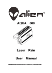
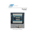
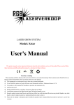
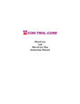
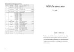
3DCURE™ Multi-Dimensional
Measurement System
System Installation &
Operators Manual
1
Table of Contents
System Components............................................................................................4
Data Collection Module ..................................................................................4
Sensors ............................................................................................................4
Software ..........................................................................................................5
Mounting Hardware ........................................................................................5
Sensor Extractor Tool .....................................................................................5
Power Supply ..................................................................................................5
Preparations for Use............................................................................................5
3DCURE™ DCM Sensor Kit...........................................................................5
Sensor Installation...........................................................................................6
Other Mounting Options .................................................................................6
Connecting the Sensors ...................................................................................6
Computer Setup...............................................................................................7
Software Installation .......................................................................................7
Sensor Software Configuration .......................................................................7
Operation ............................................................................................................9
Operation Instructions, Step-by-Step ............................................................10
Maintenance/Battery/Calibration ......................................................................13
Battery Charging ...........................................................................................13
Calibration ....................................................................................................13
Specifications....................................................................................................14
Warranty and Returns .......................................................................................15
New Product Warranty..................................................................................15
Calibration and Repair Warranty ..................................................................16
Returning the Instrument to EIT Instrument Markets ...................................16
Address for Returning All Instruments to EIT-IM ............................................17
Appendix A.......................................................................................................18
Optics Cleaning Instructions .........................................................................18
Optics Cleaning Instructions, Continued.......................................................19
Table of Figures
Figure 1.
Figure 2.
Figure 3.
Figure 4.
Figure 5.
Figure 6.
The 3DCURE™ Multi-Dimensional Curing Measurement System .....3
Data Collection Module (DCM) .........................................................4
3DCURE™ Sensor ..............................................................................4
Sensor Positioner ................................................................................4
Sensor Software Set Up Screen ..........................................................8
Software Data Collection Screen (Functions Listed Below).............11
2
Introduction
Three Dimensional (3D) UV measurement has previously proven to be a
challenge. The EIT Instrument Markets 3DCURE™ Multi -Dimensional
Curing Measurement System now enables you to accurately monitor and
profile any 3D object with multiple UV radiometers, or sensors. This is done
by allowing the user to place UV sensors on the surfaces of complex and
irregular shapes associated with 3D objects. The system is perfectly suited for
measuring UV energy density and irradiance on the surfaces of 3D objects
such as automotive bodywork, SMC and composite assemblies, wood,
furniture, and a multitude of other 3D applications.
The 3DCURE™ Multi-Dimensional Curing Measurement System can be
configured to measure UV energy density and peak irradiance in four EIT
bandwidth ranges depending on which is specified: UVA (320-390nm), UVB
(280-320nm), UVC (250-260nm), and UVV (395-445nm). The bandwidths
can be intermixed in the same system chain.
The UV 3DCURE™ Multi-Dimensional Curing Measurement System
integrates multiple UV sensors with a Data Collection Module (DCM).
Sensors are placed at various locations on an object to collect UV energy data
within a process system. The measurement system collects data through UV
sensors and transmits that data to the DCM. Once UV measurement has taken
place, UV energy density and peak irradiance data is transferred to a computer
where it is displayed and can be monitored using the Cure_3D™ software.
Figure 1. The 3DCURE™ Multi-Dimensional Curing Measurement System
3
System Components
Data Collection Module
The 3DCURE™ System's Data Collection Module (DCM) is a portable,
battery powered unit that travels with the sensors as they are exposed to UV
energy. Data is transferred to the PC by connecting the DCM to the PC.
The DCM's pushbutton controls the primary functions of the system and the
LED indicator notifies the user of the system's status.
Figure 2. Data Collection Module (DCM)
Sensors
Each sensor provided is a digital mini-radiometer with a single spectral
bandwidth (identified by the decal on the sensor itself). The sensors are
round with an optics window in the center. The two flattened insets house
the cabling connectors and LED indicators. Necessary cabling is provided
to link the sensors to the DCM and other sensors in the system chain.
Figure 3. 3DCURE™ Sensor
4
Software
The 3DCURE™ System is provided with Cure_3D™ software. This
interface allows you to communicate to the sensors and DCM and display
the collected data. Microsoft Active X© controls allow end user
manipulation of the data within other programs.
Mounting Hardware
The 3DCURE™ System kit is provided with mounting hardware for the
sensors. Other mounting options can also be used (see "Other Mounting
Options").
Figure 4.
Sensor Positioner
Sensor Extractor Tool
A spring action clamping tool can used to remove the sensor from the
positioner. The tips of the tool fit into the grooves on the recessed section of
the sensor above the connectors.
Power Supply
A universal 100-240VAC switching power supply is provided and includes
multiple plug adapters for global locations.
Preparations for Use
3DCURE™ DCM Sensor Kit
The DCM unit, sensors, and cabling kit come from the factory packed in its
own zippered storage case. The components are ready for use after
verifying that the DCM's battery is charged.
5
Sensor Installation
The 3DCURE™ sensors can be hard mounted on a 3D part by using the
Positioner mounting hardware. This device enables the sensors to be
removed from the positioners and then reinserted, providing repeatability of
the exact location of the sensor. This method requires drilling a 2.25 inch
(5.71cm) round hole in the test fixture. Once the Positioner is inserted into
the hole, secure it with the provided screws.
Prior to inserting a sensor into the positioner, the cabling needs to be
carefully connected to one or both connectors located on the sides of the
unit. Once the cables are connected, insert the sensor unit into the
positioner through the top. The retaining ring will hold the sensor securely
in place and you will be able to route the cabling either up through the top
or down through the bottom of the part.
NOTE:
Ensure that the sensors are inserted with the optic window facing up toward
the UV source.
Other Mounting Options
The sensors can also be mounted alternatively on fixture surfaces by using
any securing type materials such as adhesive magnetic strips (sensors have a
steel back plate), Velcro, tape, etc. In this method, ensure that the sensors
are stable in their mounting positions and that the optics window is not
covered.
Connecting the Sensors
Once the sensors are mounted, connect the cabling between the sensors in
the system chain. Connect the DCM-to-Sensor Cable into the DCM's 9-pin
connector, labeled "Sensor Cable". Then, connect the DCM-to-Sensor
Cable into the first sensor in the system chain.
NOTE:
Use caution when connecting and disconnecting the cabling to prevent
damage. The cables should be inserted or removed by pulling on the
connector.
6
Computer Setup
The Cure_3D™ software needs to be installed and configured properly to
work with the 3DCURE™ System. Configuration is done via the Set Up
screen within the Cure_3D™ software (see "Software Configuration"
below). When adding additional sensors to your system for the first time,
the sensor serial number must be added to the sensor list.
Software Installation
1.
Insert the Cure_3D™ software CD-Rom into your CD-Rom drive.
If “Auto Run” is set to “On” for your CD drive, the program will begin
loading automatically. Click on the ‘Finish’ and/or ‘Next’ buttons until
installation is complete.
If “Auto Run” is not turned on, follow the steps below:
2.
3.
4.
5.
6.
7.
Click on the Start button on your Windows toolbar.
Click on Run.
Click on Browse.
Select the drive where the CD Installation Disk is located.
Select the setup.exe file and double-click it.
Follow the on screen prompts by clicking on the ‘Finish’ and/or ‘Next’
buttons until installation is complete.
Sensor Software Configuration
1.
2.
3.
4.
5.
Connect the DCM via the 9-pin cable to the associated port on your PC
and the connection labeled "PC Cable" on the DCM.
Start the Cure_3D™ software program from the Start menu on your
desktop or by clicking on the Cure_3D™ icon on your desktop.
Click on the “Set Up” button on the Cure_3D™ screen.
The "Unit S/N" table may have up to 32 entries. Eight are visible in the
“Unit S/N” column at one time. The position indicator on the side of
the fields shows the location in the table of the top entry in that
column. Entering “0” in the position indicator returns the column to the
top of the table. Sensor data will be reported in the order the sensors
appear in the table. The sensors do not need to be in any particular
order.
Enter the serial numbers of your sensors (as indicated on the face of the
sensor) into the "Unit S/N" fields of the Software interface.
7
6.
7.
8.
Select the serial communications port for your computer.
Click on “Exit” to save your entries or exit without changing.
On the Data Collection Screen, the serial numbers entered will now
appear, and the correct setup can be verified by connecting the sensor
string to the DCM, then clicking on the LED button that corresponds
with each sensor. A yellow LED on the sensor will illuminate.
NOTE:
When adding additional sensors to the system for the first time, repeat
this section
Figure 5. Software Set Up Screen
8
Operation
Once the system and the software are properly installed and configured, the
system is ready to perform data collection. The pushbutton on the DCM acts
as the main switch for the DCM.
To activate the unit and to toggle through each mode, press the pushbutton.
The LED will indicate the mode in which the unit is operating.
Standby Mode
Standby Mode is indicated by a continuous RED LED. The system is
in Standby Mode before or after data collection is activated. In Standby
Mode, the system will transfer the last collected sensor data to your PC
when requested.
*A flashing RED LED indicates that a sensor listed in the
Serial Number file is not connected in the chain.
Run Mode
Run mode is indicated by a continuously GREEN LED. The system is
in Run Mode when the sensor chain is active. Once entered into this
mode, total UV energy and peak intensity data is being collected.
*A flashing GREEN LED indicates that a sensor listed in the
Serial Number file is not connected in the chain.
When the unit transitions from Standby to Run Mode, all previous
accumulated sensor data is reset. Upon transition from Run to Standby Mode,
sensor data is accumulated and ready to be transferred to the PC for viewing.
9
Operation Instructions, Step-by-Step
1.
Install the sensors and connect them together in a daisy chain using the
sensor-to-sensor cables.
2.
Connect the DCM-to-Sensor cable to the first sensor in the system
chain, and to the 9-pin connector on the DCM, labeled "Sensor Cable".
3.
Turn on the DCM unit by pressing the pushbutton, which will also
return it from Sleep Mode (LED will be red).
4.
Press the pushbutton to enter Run mode (LED will be Green).
5.
After exposure to the UV lamp system, press the pushbutton to send
data from the sensors to the DCM and place the unit in Standby Mode.
The LED will be RED.
6.
The DCM can be disconnected from the system chain and brought to
the PC for data transfer.
7.
Connect the DCM via the 9-pin cable to the associated port on your PC
and the connection labeled "PC Cable" on the DCM.
8.
Start the Cure_3D™ software.
9.
Transfer data from the DCM to the PC by clicking the GET DATA
button on the software interface.
10. Press the pushbutton to return the unit to Sleep Mode.
10
Figure 6. Software Data Collection Screen (Functions Listed Below)
11
Data Collection Screen Functions
1.
GET DATA: Click this button to transfer the collected data from the
DCM to the Cure_3D™ software data collection screen. Collected data
will appear in the Irradiance and Energy columns.
*NOTE: When taking a reading “NaN” will appear in the Irradiance
and Energy columns if a sensor is not connected or not included in the
current chain, or is malfunctioning.
2.
SAVE TEXT FILE: Click this button to save the collected data
displayed on the screen. The file will be saved in the "3DCure" folder
with a default extension of .txt.
3.
SET UP: Click this button to enter the Set Up screen and to indicate the
Software Version Number.
4.
EXIT: Click this button to exit and close the Cure_3D™ software.
5.
UNIT S/N: Serial number of the sensor.
6.
UNIT TYPE: The bandwidth of the sensor-UVA, UVB, UVC, UVV.
An extension is added to indicate the dynamic range of each sensor, and
is by –S (Standard), -H (High), or –L (Low).
NOTE:
The bandwidth is stored in the sensor and will be displayed in the table after
the first readings are made by clicking on the “GET DATA” button.
7.
LED: When connected to a PC, clicking on the LED button will
activate the associated sensor LED, providing a visible indication of the
sensor's location.
12
Maintenance/Battery/Calibration
Battery Charging
The NiMH battery in the DCM will normally allow 60 minutes of
continuous measurement with up to 32 sensors when fully charged. When
not in Run Mode and with the 100-240V charger connected, the battery will
fully recharge in approximately 1 hour.
Calibration
Each sensor is calibrated and serialized upon initial production. EIT
Instrument Markets recommends calibration every 6 months.
Carefully pack the 3D sensors in the provided 3DCURE™ storage case or in
ESD-safe material and return to:
EIT-IM
108 Carpenter Drive
Sterling VA, 20164 USA
Attention: Calibration Department
Include your company name, address, phone number, fax number, and email address on your shipping documents. EIT Instrument Markets will
contact you if any additional information is needed
13
Specifications
Sensors
Bandwidth (sensors)
Resolution
Sample Rate
Sensor Size
Data Collection Module Size
Range:
Battery
Case
Up to a maximum of 32 can be
accommodated
UVA (320-390nm), UVB (280320nm), UVC (250-260nm), and UVV
(395-445nm).
1 part in 10,000, with standard range
set at 2W.
Effective sample rate of 32 samples
per second.
1.75" diameter (4.5cm) by 0.5 H
(1.27cm)
4.5"L (11.43cm) x 2.75"W 7.0cm) x
0.8"H 2.03cm)
Standard or Optional Low Power or
High Power range available.
Standard Range: 20mW-2W
Low Power: 2mW-200mW
High Power: 200mW-2W
(Note - High Power range not
available for UVC)
Rechargeable NiMH
Zippered Case with separate sensor
pouch.
14
Warranty and Returns
New Product Warranty
EIT Instrument Markets warrants that all goods described in this manual
(except consumables) shall be free from defects in material and
workmanship. Such defects must become apparent within six months after
delivery of the goods to the buyer.
EIT Instrument Markets' liability under this warranty is limited to replacing
or repairing the defective goods at our option. EIT Instrument Markets shall
provide all materials and labor required to adjust, repair, and/or replace the
defective goods at no cost to the buyer only if the defective goods are
returned, freight prepaid, to EIT during the warranty period.
EIT Instrument Markets shall be relieved of all obligations and liability
under this warranty if:
1.
The user operates the device with any accessory, equipment, or
part not specifically approved, manufactured, or specified by
EIT, Inc., unless the buyer furnishes reasonable evidence that
such installations were not a cause of the defect. This
provision shall not apply to any accessory, equipment, or part
that does not affect the proper operation of the device.
2.
Upon inspection, the goods show evidence of becoming
defective or inoperable due to abuse, mishandling, misuse,
accident, alteration, negligence, improper installation, lack of
routine maintenance, or other causes beyond our control.
3.
The goods have been repaired, altered, or modified by other
than EIT authorized personnel.
4.
The buyer does not return the defective goods, freight prepaid,
to EIT within the applicable warranty period.
There are no warranties that extend beyond the description on the face
hereof. This warranty is in lieu of - and is exclusive of - any and all other
expressed, implied, or statutory warranties or representations. This
exclusion includes merchantability and fitness, as well as any and all other
obligations or liabilities of EIT Instrument Markets. EIT Instrument Markets
15
shall not be responsible for consequential damages resulting from
malfunctions of the goods described in this manual.
No person, firm, or corporation is authorized to assume for EIT Instrument
Markets, any additional obligation or liability not expressly provided for
herein except in writing duly executed by an officer of EIT Instrument
Markets.
If any portion of this agreement is invalidated, the remainder of the
agreement shall remain in full force and effect.
This warranty shall not apply to any instrument or component not
manufactured by EIT Instrument Markets.
Calibration and Repair Warranty
EIT Instrument Markets will warranty for 90 days from the date of
calibration and/or repair the services just performed. This Calibration and
Repair Warranty does not apply to nor cover repairs that may otherwise
occur to the instrument. Such repairs may be covered under the New
Product Warranty based on the age of the instrument.
Returning the Instrument to EIT Instrument Markets
1.
Warranty Repair:
Contact EIT Instrument Markets before returning your unit for warranty
repair.
When returning the equipment under warranty, include the cabling,
software, and charger sent with the equipment so that EIT Instrument
Markets can evaluate the system.
Please return the equipment in the original (or equivalent) packaging.
You will be responsible for damage incurred from inadequate
packaging, if the original packaging is not used.
The purchaser is responsible for insuring the unit during
transportation to EIT Instrument Markets.
Equipment repaired under warranty will be returned to the user with no
charge for the repair or shipping. EIT Instrument Markets will notify
16
you of repairs not covered by warranty and their cost prior to
performing any work on the equipment.
EIT Instrument Markets reserves the right to make changes in design at
any time without incurring any obligation to install the same on units
previously purchased.
1.
Non-Warranty Repair or Instruments Returned for Calibration:
You do not need to contact EIT Instrument Markets before returning
your unit for repair or calibration.
Please return the equipment in the original (or equivalent) packaging to
the address provided above in the Warranty Returns section (Specify
"Non-Warranty Returns Department"). You will be responsible for
damage incurred from inadequate packaging, if the original packaging
is not used.
The customer is responsible for insuring the unit during
transportation to EIT Instrument Markets.
EIT Instrument Markets will contact you with the needed repairs and
the cost of repair before service begins. Repair service on calibrated
units includes calibration.
Address for Returning All Instruments to EIT-IM
Ship the unit, freight prepaid, to the address below:
EIT-IM
108 Carpenter Drive
Sterling, VA 20164 USA
Attention: Returns Department
Include your company name, address, telephone number, fax number, and email address on your shipping documents. EIT Instrument Markets will
contact you if any additional information is needed.
17
Appendix A
Optics Cleaning Instructions
The following guidelines are for cleaning the optical surfaces on EIT
instruments. However, EIT cannot have full knowledge of contaminants
present in all applications and as a result cannot test for their effects.
Therefore, we cannot assume responsibility for damage to customer
instruments, which results from following these directions once the warranty
period has expired. Also, it is the customer's responsibility to obtain and read
the MSDS for any chemical used for cleaning optics, and for taking necessary
precautions. EIT makes no claim for the safety of any of these chemicals.
1. LOOK.
Closely examine the optical surface. If no contaminant is visible, it is best
to not clean the instrument. The optics are delicate and handling should
be minimized. If contaminants are not visible, cleaning should only be
done if:
a.) It is known that a contaminant has come in contact with the
instrument's optics.
b.) A shift in readings has been observed with the instrument, and the
design of the UV system is such that contamination on the radiometer
is a possible cause of measurement error.
2. BLOW.
The next step is to use compressed gas to remove any loose material from
the surface of the optics. Loose material, especially silicates and other
abrasive components, can cause scratching of the optical surface. The
best solution is to use canned dry nitrogen. Tetrafluoroethane-based
products commonly known as “dusters” are an acceptable, cost-effective
alternative. For these products, care should be taken to avoid making the
optic too cold, which will cause condensation on the optic. Also, a
rubber air bulb is a simple and effective method for removing loose
particles from the window.
It is best not to blow on the optics with the mouth; various components of
saliva are difficult to remove from the optics. It is also advisable to
AVOID COMPRESSED (SHOP) AIR because of the difficulty in
removing oil from the optical surface.
18
Optics Cleaning Instructions, Continued
3. FLOOD.
Apply a liberal amount of solvent to the window. The purpose of the
solvent is to loosen the contaminants from the surface, so that surface
tension can remove the contaminant in step 4. EIT recommends cleaning
the optic once with isopropyl alcohol, and once with acetone for best
results. Other suitable solvents include de-ionized water, methyl alcohol,
and ethyl alcohol. Customers working with non-polar chemicals may find
Methyl-ethyl-ketone (MEK) to be an effective solvent. Customers should
avoid using solutions containing detergents.
4. WIPE.
Using a lint-free wipe or a cotton swab, wipe the surface clean. The wipe
or swab needs to be thoroughly saturated with the solvent, so the surface
tension of the solvent will allow the contaminant to be captured on the
wipe, and so the wipe does not abrade the optical surface. Again, users
may find it convenient to start again at step 3 with a second solvent.
EIT can provide cleaning advice, assistance, and repair or replacement in
cases where these guidelines fail to remove contaminants. These
guidelines will help ensure the radiometer user long life and accurate
readings from their instrument.
19