1
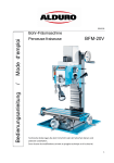
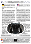
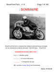
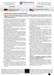
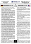
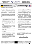
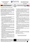
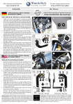
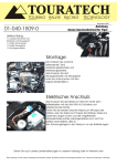
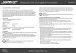
News, Downloads und Informationen
The latest catalogue sections and news
www.wunderlich.de
www.wunderlich.de/update
Anbauhilfe
User Manual
Artikel: Zusatzscheinwerfer R 850/1100/1150 GS
Bestellnummer: 8600475
Part: Additional Lights R 850/1100/1150 GS
Part number: 8600475
Vielen Dank für Ihr Vertrauen zu unserem Produkt.
Thank you for purchasing our product.
Installation should be easy if you follow these instructions. TIP: Having a
nearly empty tank will make removing and installing the fuel tank easier.
1. Nehmen Sie die Sitzbänke ab und demontieren Sie die Tankverkleidung.
2. Ziehen Sie die beiden Benzinschlauchkupplungen durch drücken auf die
seitliche Verriegelungstaste auseinander, ziehen Sie den Benzinpumpenstecker
ab, ziehen Sie die Entlüftungsleitungen an den Verbindugsstücken
auseinander, drehen Sie die Tankbefestigungsschraube heraus, heben Sie
den Tank hinten an und nehmen Sie diesen nach hinten vom Fahrzeug ab
(Bild A).
3. Klemmen sie den Minuspol an der Batterie ab und befestigen Sie das Relais
mit den Masseanschlußösen an der oberen Befestigungsschraube auf der
linken Seite des Steuergerätes (Bild B).
4. Verlegen Sie das rote Kabel mit dem Sicherungshalter zur Batterie (achten
Sie hierbei darauf das die Sicherung gut zu erreichen ist), entfernen Sie die
Sicherung und klemmen Sie das Kabel am Pluspol an.
5. Verlegen Sie die Kabel für Schalter und Scheinwerfer entlang des linken
Schnabel-Halterahmen bis unter den linken Blinker, klemmen Sie das
Massekabel an der Batterie wieder an, befestigen Sie alle Kabel mit
Kabelbinder am Fahrzeug. Achten Sie hierbei darauf, das keine Leitungen
gequetscht werden, den Lenkeinschlag begrenzen oder an Fahrzeugteilen
scheuern können.
6. Montieren Sie den Tank wieder am Fahrzeug.
7. Nun können Sie den Schalter an einer freien Stelle ins Cockpit einbauen.
Die Abbildung zeigt den Einbau bei der R1150 GS (Abb. C). Zur Montage
muß vorher der Scheinwerfer demontiert werden.
8. Verlegen Sie nun das einzelne, schwarze Kabel vom Schalter zur vorderen
Standlichtbirne und klemmen Sie es mit einem Kabelverbinder am grau/
schwarzen Standlichtkabel an (Bild D).
9. Bauen Sie nun die beiden Scheinwerferhalter mit je einer Senkkopfschraube
M5, U-Scheibe und Mutter zusammen (Bild E).
10. Demontieren Sie den Haltebügel an den Zusatzscheinwerfern, setzen Sie
die Scheinwerfer mit je zwei Distanzhülsen 11,5mm in die Aluhalter und
befestigen Sie diese an der dem Fahrzeug abgewandten Seite mit einer
Schraube M6x20 und U-Scheibe sowie von der dem Fahrzeug zugewandten
Seite mit einer Schraube M6x25 und U-Scheibe (Bild F).
11. Entfernen Sie die beiden unteren Befestigungsschrauben am Schnabel.
12. R1150GS & Adventure:
Montieren Sie die Scheinwerferhalter mit je zwei Schrauben M5x16 und
kleinen Hülsen (als Distanz zwischen Halter und Schnabel) am Fahrzeug
(Bild G). Schieben Sie ein passendes Stück kleinen Schrumpfschlauch
über die beiden Kabel des Scheinwerfers, ein passendes Stück großen
Schrumpfschlauch über die Zuleitung und verbinden Sie die Steckanschlüsse.
Durch Erwärmung (z.B. Heißluftfön) legt sich der Schrumpfschlauch
passgenau über die Steckanschlüsse und Leitung. Befestigen Sie das Kabel
vorne am Halter mit einem Kabelbinder (Bild H).
R850/1100GS:
Entfernen Sie den hinteren Blechmuttereinsatz. Montieren Sie die
Scheinwerferhalter vorne mit der beiliegenden, längeren Blechschraube und
U-Scheibe 3,7mm sowie hinten mit einer Schraube M5x16, U-Scheibe und
Mutter. (Verwenden Sie auch hier die kleinen Hülsen als Distanz zwischen
Halter und Schnabel am Fahrzeug). Schieben Sie ein passendes Stück
kleinen Schrumpfschlauch über die beiden Kabel des Scheinwerfers, ein
passendes Stück großen Schrumpfschlauch über die Zuleitung und verbinden
Sie die Steckanschlüsse. Durch Erwärmung (z.B. Heißluftfön) legt sich
der Schrumpfschlauch passgenau über die Steckanschlüsse und Leitung.
Befestigen Sie das Kabel vorne am Halter mit einem Kabelbinder (Bild I).
13. Stecken Sie die beiden Kabelbefestigungsklemmen auf den Kunststoffrahmen
unter dem Ölkühler und hängen Sie das Kabel ein (Bild J).
14. Stecken Sie die Sicherung wieder in den Sicherungshalter und montieren Sie
die Sitzbank.
15. Richten Sie die Scheinwerfer aus und drehen Sie alle Schrauben fest.
Genereller Hinweis: Unsere Anleitungen sind nach bestem Wissen erstellt worden,
erfolgen jedoch ohne Gewähr. Sollten Sie mit dem Anbau nicht zurecht kommen
oder Zweifel haben, so wenden Sie sich bitte an Ihren BMW-Händler oder die
Werkstatt Ihres Vertrauens. Bitte beachten Sie , dass wir keine Gewährleistungen
für fahrzeugspezifische Toleranzen übernehmen können! Es kann im Einzelfall
notwendig sein, dass Produkte diesen angepasst werden müssen.
1. Remove the seats and remove the plastic covering on the right side of the tank.
2. Disconnect the fuel lines, the vent tubes and the electrica connector on the right
side of the tank. Remove the bolt from the right rear of the tank, (watch the nut
on the inboard side) lift the rear of the tank and remove it from the motorcycle.
(Image A)
3. Disconnect the negative (-) battery cable and then the positive (+) battery cable.
Attach the relay of the light kit wiring harness to the left upper mounting bolt of
the Motronic control unit, together with the ground wire of the harness. (Image
B)
4. Route the red wire with the fuse holder to the battery. Find an easy to reach
location for the fuse holder, remove the fuse and then connect the wire to the
positive (+) terminal of the battery.
5. Route the wires for the switch and lights along the left side beak support bracket
up to the area of the left turn signal. Reattach the negative (-) battery cable.
Attach all of the wires to suitable points with cable ties. When doing so, attach
all of the wires to the motorcycle in a clean and orderly fashion and make sure
that the wires are not pinched, interfere with the steering or are vulnerable to
abrasion.
6. Reinstall the fuel tank in the reverse order of disassembly. (Step 2)
7. Now you can mount the switch in a suitable location of the instrument panel. Image (C)
shows a good spot on the R1150 GS. Disassembly of the headlight assembly may be required.
Alternatively, you can switch the lights with an Autoswitch (not supplied). The
Autoswitch uses the turn signal cancel switch to activate/deactivate the lights.
Ask your dealer for details.
8. Route the black wire from the switch to the parking light and connect it to the
black/gray wire of the parking light using the supplied splice connector (Image
D).
9. Assemble the instrument mounting brackets using one 5mm bolt, washer and nut
on each assembly. (Image E)
10. Remove the brackets which are attached to the micro lights and place the lights
in the aluminum brackets along with the two 11.5mm spacers and then attach
them to the brackets using a 6 X 20mm bolt and washer on the outboard side and
a 6X25mm bolt and washer on the inboard side. (Image F)
11. Remove both lower mounting bolts from the underside of the beak.
12. R1150 GS & Adventure
Attach the light brackets using two 5 X 16mm bolts and small bushings (used as
spacers between the holder and the beak) to the motorcycle. (Image G) Place a
suitably sized piece of small shrink tubing over the wires attached to the light.
Place a suitably sized piece of large shrink tubing over the harness wires leading
to the lamps and then connect the wires together. Position the shrink tubing such
that it neatly covers the wires and then apply heat to the tubing with for example,
a heat gun. Attach the wiring to the bracket with a cable tie. (Image H)
12. R1100 GS:
Remove the rear sheet metal screw nuts. Attach each light bracket at the front
with the included, longer sheet metal screw and 3.7mm washer and at the rear
with 5X16mm bolt, washer and nut. Use the small bushings as spacers between
the holder and the beak. Place a suitably sized piece of small shrink tubing over
the wires attached to the light. Place a suitably sized piece of large shrink tubing
over the harness wires leading to the lamps and then connect the wires together.
Position the shrink tubing such that it neatly covers the wires and then apply heat
to the tubing with for example, a heat gun. Attach the wiring to the bracket with
a cable tie. (Image I)
13. Attach the cable clips to the plastic frame under the oil cooler and place the cable
into the clips. (Image J)
14. Reinstall the fuse into the fuse holder. Reinstall the seat(s).
15. Aim the lights and once the desired positioning has been achieved, tighten all of
the fasteners.
Copyright
by
Wunderlich
General note: Our fittings instructions are written to the best of our knowledge
but specifications or details may change. If you have difficulties or have doubts
with fitting this part please seek advice from your BMW dealer or workshop of
your choice. Please note that in some cases due to vehicle related tolerances
beyond our control some products might need adjusting to fit. We cannot
warranty parts fitting in those circumstances.
News, Downloads und Informationen
The latest catalogue sections and news
www.wunderlich.de
www.wunderlich.de/update
Anbauhilfe
User Manual
Artikel: Zusatzscheinwerfer R 850/1100/1150 GS
Bestellnummer: 8600475
Part: Additional Lights R 850/1100/1150 GS
Part number: 8600475
A
B
C
D
E
F
G
H
I
J
Allgemeine Anzugsdaten
Diese Tabelle spezifiziert Anzugsmomente für normale Befestigungselemente
mit normalen I.S.O.-Gewindenormen. Diese Anzugsmomente gelten nur, wenn
in der Anleitung keine anderen Angaben gemacht wurden. Wenn Teile mit mehreren Befestigungselementen festgezogen werden, die Schrauben und Muttern
kreuzweise und in mehreren Schritten bis zum vorgeschriebenen Anzugsmoment
festziehen, so dass keine Teile verzogen werden. Falls nicht anders vermerkt,
so gelten die Anzugsmomente für trockene und saubere Gewinde. Die anzuziehenden Bauteile sollten dabei Raumtemperatur aufweisen.
Common Torque Values.:
Schraube
Bolt
Allgemeine
Anzugsmomente
Torque Values
M6 mm
6 Nm
4.5 ft-lb
M8 mm
15 Nm
11 ft-lb
M10 mm
30 Nm
22 ft-lb
M12 mm
55 Nm
40,5 ft-lb
This table specifies tightening torques of common fasteners with standard
I.S.O. threads. These torque specifications are only valid when different
torque values are not specified by the manufacturer. When joining parts with several fasteners, evenly tighten in a cross
pattern, in several stages up to the maximum, so that the parts are joined evenly. Unless otherwise specified by the manufacturer, these torque values are for dry and clean bolts and threads, with all components at room temperature.
Schraubenlineal:
Das Lineal soll Ihnen bei der Identifizierung der Schrauben helfen.
Bitte bedenken Sie, daß Schrauben an Ihrer Einschraubtiefe gemessen
werden, also ohne Kopf. M5x25 = Durchmesser 5mm, Länge 25 mm
Metric Ruler for determining bolt sizes:
When measuring bolts, only measure the length of thread
and shaft without the bolt head. For example, M5x12
means diameter of bolt is 5 mm, length 12 mm.