1
News, Downloads und Informationen
The latest catalogue sections and news
www.wunderlich.de
www.wunderlich.de/update
Anbauhilfe
User Manual
Artikel: Zusatzscheinwerfer K 1200 LT
Bestellnummer: 8600470
Part: "MicroFlooter" Light Set K1200 LT
Part number: 8600470
Vielen Dank für Ihr Vertrauen zu unserem Produkt.
Thank you for purchasing our product.
Installation should be easy if you follow these instructions:
1. Open the seat. Disconnect the negative (-) battery cable and then the
positive (+) battery cable. Remove the right mirror as follows: Hold
the mirror with one hand and hit it sharply with the other hand from
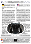
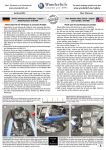
the rear until it pops off. Remove the right side wind deflector (Image
A). Remove the right front turn signal assembly from the fairing. Refer
to your Service and Technical manual if needed.
2. Remove the two screws from the plastic cover at the right side safety
bar and remove the cover. Remove the three screws of the chrome or
silver covering of the right safety bar and remove the covering. Remove
the right side of the lower fairing (Image B).
3. Flip the rear shock absorber adjustment knob up and attach the relay
together with the ground wire of the twowire cable and the relay ground
wire using the original rear fender mounting bolt (Image C).
4. Note the position of the wires connected to the toggle switch and
unplug them. Route both two-wire cables behind the fairing, along the
safety bar (parallel to the existing wiring) and through the opening
for the turn signal (Image D).
5. Mount the switch in the panel just below the headlight adjuster
(Image E). Alternatively, you can switch the lights with an Autoswitch
(not supplied). The Autoswitch uses the turn signal cancel switch to
activate/deactivate the lights. Ask your dealer for details.
6. Route the two-wire switch cable behind the fairing to the switch and
re-connect the wires (disconnected in step 4) to the switch. Pull the
parking light out of the headlight assembly. Remove about 2 inches of
insulating tape from the wires of the parking light. Route the black wire
from the switch to the parking light and connect it to the black/gray
wire of the parking light using the supplied splice connector (Image
F).
7. Push the small insulating sleeve on to the the connector of the black
wire of the lights. Attach the lights to the aluminum bracket using
2-5mm bolts, 4-washers and 2-nuts in such a way that the edge of
the light bracket lines up with the edge of the aluminum bracket
(Image G) and the lights will be as far to the outside as possible when
installed.
8. Remove the two upper screws on the inside of the fairing. Attach the
light brackets using the original screws as high up as possible (Image
H). Connect the lights to the harness wires.
9. Re-connect the positive (+) battery cable and at the same time, connect
the red wire from the relay to the positive (+) terminal of the battery.
Now re-connect the negative (-) battery cable and connect the brown
wire from the relay to the negative (-) terminal of the battery. Insert
the fuse into into the fuse holder and attach it with a cable tie to a
place that is easy to reach if needed (ImageI).
10. Attach all of the wires to the motorcycle in a clean and orderly fashion.
Make sure that the wires are not pinched or vulnerable to abrasion.
11. Re-attach the lower fairing, safety bar covers, wind deflector, mirror
and turn signal which were previously removed. Check for proper fit and
function. Bounce the front of the motorcycle up and down, with the
front wheel turned in all possible positions and check to make sure that
there is no contact. This may be easier if a friend helps. In the unlikely
event that there is contact of the lights with the front fender or forks,
the position of the lights may need to be altered or modified.
1. Klappen Sie den Fahrersitz hoch und klemmen Sie zuerst den Minusund anschließend den Pluspol an der Batterie ab. Halten Sie den
rechten Spiegel mit einer Hand fest, demontieren Sie ihn durch einen
leichten Schlag mit der anderen Hand von hinten gegen den Spiegel
und schrauben Sie den rechten Windabweiser ab (Bild A). Schrauben
Sie das Blinkergehäuse vorne rechts herraus und demontieren Sie die
Blinkerfassung (siehe auch BMW-Service und Technik Heft).
2. Entfernen Sie die beiden Inbusschrauben am rechten, schwarzen
Kunststoffsturzschutz und nehmen Sie diesen ab. Enfernen Sie die
drei Torxschrauben an der Chromleiste und nehmen Sie auch diese ab.
Demontieren nun die rechte Seite des Bugspoilers (Bild B).
3. Klappen Sie das Handrad für die Dämpferverstellung nach oben und
befestigen Sie das Relais mit den Masseanschlüssen der 2adrigen Kabel
und der Relaismasse mit der Originalkotflügelschraube (Bild C).
4. Markieren Sie die Position der Stecker am Schalter ziehen diese ab,
verlegen Sie die beiden 2adrigen Kabel hinter der Verkleidung, am
Sturzbügel entlang (parallel der vorhandenen Leitungen) und durch die
Blinkeraussparung (Bild D).
5. Montieren Sie den Schalter unterhalb der Scheinwerfereinstellung, links
neben die Kontrollleuchte der Alarmanlage (Bild E).
6. Verlegen Sie das 2adrige Schalterkabel hinter der Verkleidung zum
Schalter und klemmen Sie dieses und das schwarze Steuerkabel wieder
am Schalter an. Ziehen Sie die Standlichtfassung aus dem Scheinwerfer,
entfernen Sie ca. 5 cm vom Isolierband der Standlichtleitung, verlegen
Sie das schwarze Steuerkabel vom Schalter zur Standlichtfassung
und klemmen Sie dieses mit der Kabelklemme am grau/schwarzen
Standlichtkabel an (Bild F).
7. Schieben Sie die kleine Isoliertülle auf den Steckanschluss vom schwarzen
Kabel des Zusatzscheinwerfers. Montieren Sie die Zusatzscheinwerfer mit
je 2 Schrauben M5, 4 U-Scheiben und Muttern so auf dem Aluhalter, das
der Bügel der Lampe mit dem hinteren Ende des Aluhalters eine Linie
bildet (Bild G) und der Scheinwerfer später am Fahrzeug so weit wie
möglich aussen sitzt.
8. Drehen Sie die beiden oberen Schrauben innen in der Verkleidung herraus,
befestigen Sie den Scheinwerferhalter so hoch wie möglich mit den
Originalschrauben (Bild H) und schließen Sie die Scheinwerfer an die
Zuleitung an.
9. Schließen Sie zuerst das rote Kabel vom Relais mit den Plusleitungen vom
Fahrzeug an der Batterie an. Schließen Sie nun das braune Massekabel
vom Reais mit den Massekabeln vom Fahrzeug an der Batterie an,
stecken Sie die Sicherung in den Sicherungshalter und befestigen Sie
den Sicherungshalter mit einem Kabelbinder so am Fahrzeug, das er gut
erreichbar ist (Bild I).
10. Befestigen Sie alle Kabel mit Kabelbindern am Fahrzeug, achten
Sie hierbei darauf, das die Kabel niergendwo scheuern können oder
gequetscht werden.
11. Montieren Sie Bugverkleidung, Chromleiste, Kunststoffsturzschutz,
Windabweiser, Spiegel und Blinker wieder am Fahrzeug und
überprüfen Sie durch eintauchen des Vorderrades (diese Prüfung
kann am einfachsten mit zwei Personen durchgeführt werden) mit
unterschiedlichem Lenkeinschlag,das die Scheinwerfer nicht gegen
Gabel oder Kotflügel stoßen (eventuell muß die Scheinwerferposition
noch den fahrzeugspezifischen Tolleranzen angepasst werden).
Genereller Hinweis: Unsere Anleitungen sind nach bestem Wissen erstellt worden,
erfolgen jedoch ohne Gewähr. Sollten Sie mit dem Anbau nicht zurecht kommen
oder Zweifel haben, so wenden Sie sich bitte an Ihren BMW-Händler oder die
Werkstatt Ihres Vertrauens. Bitte beachten Sie , dass wir keine Gewährleistungen
für fahrzeugspezifische Toleranzen übernehmen können! Es kann im Einzelfall
notwendig sein, dass Produkte diesen angepasst werden müssen.
Copyright
by
Wunderlich
General note: Our fittings instructions are written to the best of our knowledge
but specifications or details may change. If you have difficulties or have doubts
with fitting this part please seek advice from your BMW dealer or workshop of
your choice. Please note that in some cases due to vehicle related tolerances
beyond our control some products might need adjusting to fit. We cannot
warranty parts fitting in those circumstances.
News, Downloads und Informationen
The latest catalogue sections and news
www.wunderlich.de
www.wunderlich.de/update
Anbauhilfe
User Manual
Artikel: Zusatzscheinwerfer K 1200 LT
Bestellnummer: 8600470
Part: "MicroFlooter" Light Set K1200 LT
Part number: 8600470
A
B
C
D
E
F
G
H
I
Schraubenlineal:
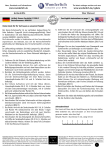
Das Lineal soll Ihnen bei der Identifizierung der Schrauben helfen.
Bitte bedenken Sie, daß Schrauben an Ihrer Einschraubtiefe gemessen
werden, also ohne Kopf. M5x25 = Durchmesser 5mm, Länge 25 mm
Metric Ruler for determining bolt sizes:
When measuring bolts, only measure the length of thread
and shaft without the bolt head. For example, M5x12
means diameter of bolt is 5 mm, length 12 mm.