1
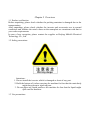
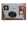
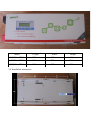
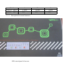
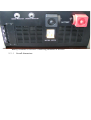
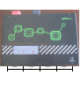
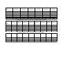
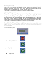
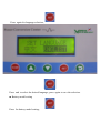
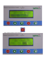
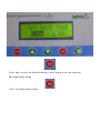
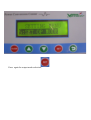
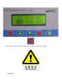
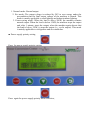
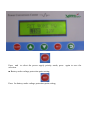
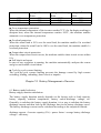
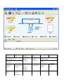
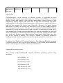
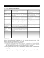
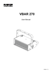
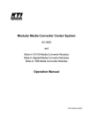
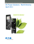
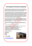
Preface
Thank you for using the pure sine wave inverter of Beijing Multifit Electrical
Technology Co., Ltd.
This User Manual is about the functions and operation process of the inverter. Please
read this User Manual carefully before operation for correctly using the inverter and
keep this User Manual properly for future reference in case of any problem.
Attentions:
■ This User Manual is subject to change without notice and the latest version
prevails.
■ In case of any different understanding of this User Manual, the interpretation
from Technology Department of Beijing Multifit Electrical Technology Co.,
Ltd. prevails.
■ Any copying or rearranging of any part or whole of this User Manual without
the written permission from Beijing Multifit Electrical Technology Co., Ltd.
is considered as serious infringement.
Table of Contents
Chapter I Overview
1.1 Product verification
1.2 Safety precautions
1.3 Use precautions
Chapter II Product Specification
2.1 Application range
2.2 Types
2.3 Technical specifications
2.4 Description of external structure
2.5 Overall dimensions
2.6 Installation dimensions
2.7 Optional accessories
Chapter III Installation and Wiring of Inverter
3.1 Environmental conditions for installation
3.2 Wiring precautions
Chapter IV Operation Guide of Inverter
4.1 Operation
4.2 Parameters
Chapter V Performance and Parameters of Inverter
5.1 Capacity calculation
5.2 Performance and parameters
Chapter VI Battery Management of Inverter
6.1 Battery model selection
6.2 Battery insertion
Chapter VII Monitoring
Chapter VIII Maintenance
8.1 Daily maintenance
8.2 Periodic maintenance
8.3 Fault diagnosis and handling
8.4 Warranty
Chapter I Overview
1.1 Product verification
Before unpacking, please check whether the packing container is damaged due to the
transportation.
After unpacking, please check whether the inverter and accessories are in normal
conditions and whether the rated values on the nameplate are consistent with that in
your order requirements
In case of any exception, please contact the supplier or Beijing Multifit Electrical
Technology Co., Ltd.
1.2 Safety precautions
Attentions:
1. Do not install the inverter which is damaged or short of any part.
2. Hold the bottom of it when carrying the machine for fear that the main body
might drop down to injure anyone.
3. Do not place any liquid on/above the machine for fear that the liquid might
spill onto the machine.
1.3 Use precautions
Dangers:
1. Make sure that the power is shut off before wiring.
2. Have an electrical technician wire the machine up.
3. Have the grounding terminal reliably grounded.
4. Do not touch any terminal by hand.
5. Make sure that the battery polarity is correct.
Attentions:
1. Make sure that the voltage of the AC circuit is as same as the rated voltage
of the inverter.
2. Do not disconnect any terminal while the machine is powered on and
running.
3. Do not touch the battery switch while the battery is being charged at a high
current.
4. Do not clog the ventilation hole of the machine.
5. Do not wipe the machine casing by wet cloth.
Chapter II Product Specification
2.1 Application range
■ Important computer systems in securities exchanges, bank, hospitals, etc.;
■ Fire protection, lighting, monitoring and other systems in buildings;
■ Transportation systems covering lighting systems in expressways, tunnels,
metros, airports, etc.;
■ Production, experimental and other equipment which must not be powered off;
■ Household electrical appliances.
2.2 Types
■ Household inverter
■ Solar inverter
■ Pure inverter
2.3 Technical specifications
Data Model
Item
500VA
Rated Output
Power
Maximum
Output
Current
350W
1.6A
(3.2A
)
1,000V
A
700W
2,000V
A
1,400W
3,000V
A
2,100W
4,000V
A
2,800W
5,000V
A
3,500W
6,000V
A
4,200W
8,000VA
3.2A
(6.4A)
6.4A
(12.8A)
9.5A
(19A)
12.7A
(25.4A)
15.9A
(31.8A)
19.1A
(38.2A)
25.5A
(50.9A)
Rated Output
Voltage
Rated Output
Frequency
Output
Waveform
220VAC±1% (110VAC±1%)
Distortion
Degree
Inversion
Efficiency
Overload
Capacity
≤3%
Input
Battery
Voltage
Battery
Voltage
Range
5,600W
50Hz±0.5% (60Hz±0.5%)
Pure sine wave
80%~85%
When the load is 120% to 160% of the rated load, the machine maintains output for
7s to 10s; when the load is 160% to 200%, the machine maintains output for 3s to 7s;
when the load is over 200%, the machine maintains output for 1s, shuts down and
gives out long alarm sounds
DC Input
12V / 24V / 48V
10V-16V / 20V-32V / 40V-64V
AC Input
Input
Voltage
Range
160~270VAC (95VAC-140VAC)
Input
Frequency
Range
45~55Hz (55~65Hz)
Power
Factor
0.9
Output
Voltage
Accuracy
As same as that of mains supply
Output
Frequency
Accuracy
Charge
Voltage
Charge
Current
Conversion
Time
Protection
Function
Machine
Noise
Working
Ambient
Temperatur
e
Working
Ambient
Humidity
Working
Ambient
Height
Synchronous with the input frequency
13.7V / 27.5V / 55V
10A / 20A(30A) / 30A(50A)
Other Parameters
≤4mS
Over-temperature protection / overload protection / short circuit protection / battery
under-voltage protection / battery over-voltage protection
≤40Db(1mter)
-20~50℃
5%~90% (no droplet condensed)
2.4 Description of external structure
≤1,500M
LCD control panel of inverter
Battery terminals of inverter
Connecting terminals of inverter
2.5 Overall dimensions
Model
Length
Width
Height
0.5KVA~1KVA
470mm
195mm
180mm
1.5KVA~2KVA
510mm
250mm
200mm
2.5KVA~5KVA
585mm
255mm
200mm
2.6 Installation dimensions
Model
0.5KVA~1KVA
1.5KVA~2KVA
2.5KVA~5KVA
2.4-1
A
175mm
235mm
235mm
Description of external structure
LED control panel of inverter
B
155mm
182mm
212mm
C
155mm
162mm
212mm
Battery terminals of inverter/ Connecting terminals of inverter
2.5-1
Overall dimensions
Model
Length
Width
Height
0.5KVA~5KVA
435mm
295mm
203mm
2.6 -1 Installation dimensions
Model
0.5KVA~5KVA
A
443mm
2.4-2 Description of external structure
B
191mm
LCD control panel of inverter
Battery terminals of inverter/ Connecting terminals of inverter
2.5-2
Overall dimensions
Model
Length
Width
Height
0.5KVA~1KVA
302mm
161mm
280mm
1.5KVA~5KVA
400mm
207mm
328mm
6KVA~8KVA
440mm
270mm
400mm
2.7 Optional accessories
■ RS232 + monitoring product + communication line
■ USB + monitoring product + communication line
■ Battery cable
■ Input/output cable
■ Remote LCD monitoring panel
Chapter III Installation and Wiring of Inverter
3.1 Environmental conditions for installation
■ The machine must be installed in a well-ventilated place.
■ The ambient temperature must be within -20℃ to 50℃.
■ The ambient humidity must be lower than 95%RH to ensure there is no
droplet condensed.
■ The machine must not be installed in the place where there is corrosive or
explosive gas.
3.2 Wiring precautions
Attentions:
■ Make sure that the power is shut off before wiring.
■ Make sure that the AC voltage is as same as the required voltage of the
machine before wiring.
■ Make sure that the battery voltage is as same as the required voltage of the
machine before wiring.
■ Make sure that the battery polarity is correct before wiring.
Please choose the wire with proper diameter from the wire configuration tables
below:
Configuration Table of AC110V Input/Output Wires
Model
Wire
L-IN
N-IN
G
L-OUT
N-OUT
500VA/
110VAC
≥1㎟
≥1㎟
≥1㎟
≥1㎟
≥1㎟
≥1㎟
1,000VA/
110VAC
≥2㎟
≥2㎟
≥2㎟
≥2㎟
≥2㎟
≥2㎟
2,000VA/
110VAC
≥4㎟
≥4㎟
≥4㎟
≥4㎟
≥4㎟
≥4㎟
3,000VA/
110VA
≥6㎟
≥6㎟
≥6㎟
≥6㎟
≥6㎟
≥6㎟
4,000VA/
110VAC
≥8㎟
≥8㎟
≥8㎟
≥8㎟
≥8㎟
≥8㎟
5,000VA/
110VAC
≥10㎟
≥10㎟
≥10㎟
≥10㎟
≥10㎟
≥10㎟
Configuration Table of AC220V Input/Output Wires
Mode
l
Wire
L-IN
N-IN
G
L-OUT
N-OUT
500VA/
220VAC
1,000VA/
220VAC
2,000VA/
220VAC
3,000VA/
220VA
4,000VA/
220VAC
5,000VA/
220VAC
6,000VA/
220VAC
8,000VA/
220VAC
≥0.5㎟
≥0.5㎟
≥0.5㎟
≥0.5㎟
≥0.5㎟
≥1㎟
≥1㎟
≥1㎟
≥1㎟
≥1㎟
≥2㎟
≥2㎟
≥2㎟
≥2㎟
≥2㎟
≥3㎟
≥3㎟
≥3㎟
≥3㎟
≥3㎟
≥4㎟
≥4㎟
≥4㎟
≥4㎟
≥4㎟
≥4㎟
≥4㎟
≥4㎟
≥4㎟
≥4㎟
≥6㎟
≥6㎟
≥6㎟
≥6㎟
≥6㎟
≥6㎟
≥6㎟
≥6㎟
≥6㎟
≥6㎟
500VA
1,000VA
2,000VA
3,000VA
4,000VA
5,000VA
8㎟
4㎟
2㎟
16㎟
8㎟
4㎟
25㎟
16㎟
8㎟
16㎟
10㎟
25㎟
16㎟
35㎟
16㎟
Configuration Table of Input Wires to Battery
Mode
l
DC
12V
24V
48V
6,000VA 8,000VA
16㎟
25㎟
Chapter IV Operation Guide of Inverter
4.1 Operation
Startup: when all wiring is in normal condition, press “On” for 5 seconds, and then
the machine starts up.
Shutdown: Press “Off” for 5 seconds, and then the machine shuts down.
4.2 Parameter setting
4.2.1 LED control panel
■
■
■
■
■
■
■
■
■
■
■
■
■
On/Off
Startup/Shutdown
Save
Eco Mode
Charge
Charge Current Selection
Mains
Mains Supply Indicator Light
Battery
Battery Supply Indicator Light
Output
Output Indicator Light
Fault
Fault Indicator Light
Saving
Eco Mode Indicator Light
UNDER-VOITAGE Battery Under-voltage/Over-voltage Indicator Light
CHARGING
Battery Charging Indicator Light
10A
10A Charge Current Indicator Light
30A
30A Charge Current Indicator Light
50A
50A Charge Current Indicator Light
4.2.4 Parameter setting on LED control panel
■ Setting of eco mode
Press “Save” for 5 seconds, and then the machine turns to eco mode and “Saving”
indicator light is on all the time; press “Save” again for 5 seconds, and then the
machine turns to normal mode and “Saving” indicator light is off.
This setting is invalid when the machine is powered by mains supply.
■ Setting of charge current
The user chooses the proper charge current according to the power grid environment
and battery capacity when the machine is powered by mains supply. The default
charge current is 10A; press “Charge” for 5 seconds, and then the machine increases
the charge current and the corresponding charge current indicator light is on all the
time; press “Charge” again for 5 seconds, and then the machine increases the charge
current again and the corresponding charge current indicator light is on all the time.
This setting is invalid when the machine is powered by battery supply.
Note: 25%, 50%, 75% and 100% are invalid when the machine is powered by mains
supply and they respectively indicate the battery level when the machine is powered
by battery supply.
4.2.3 LCD control panel
■
■
Startup/Shutdown
Page Up
■
Page Down
■
Function Selection
■
Back
4.2.4 Parameter setting on LCD control panel
■ Language setting
Press for language setting;
Press again for language selection;
Press and to select the desired language; press again to save the selection.
■ Battery model setting
Press for battery model setting;
Press again for battery model selection;
Press and to select the battery model consistent with the real one; press again to
save the selection.
■ Charge current setting
Press for charge current setting;
Press again for charge current selection;
Press and to select the desired charge current; press again to save the selection.
■ Frequency setting
Press for frequency setting;
Press again for frequency selection;
Press and to select the desired frequency; press again to save the selection.
■ Output mode setting
Press for output mode setting;
Press again for output mode selection;
Press and to select the output mode; press again to save the selection.
Attentions:
1. Normal mode: Normal output.
2. Eco mode: The output voltage is reduced by 20V to save energy under the
precondition that the final output voltage of the machine is normal. This
mode is mainly applicable to road lighting and indoor/outdoor lighting.
3. Power-saving mode: When the load is above 200W, the machine remains
normal output. When the load is below 150W, the machine stops the output
and, after 1 minute, starts the output; when the machine again detects that
the load is below 150W, it stops the output (i.e., cyclic output). This mode
is mainly applicable to refrigerator and air conditioner.
■ Power supply priority setting
Press for power supply priority setting;
Press again for power supply priority mode selection;
Press and to select the power supply priority mode; press again to save the
selection.
■ Battery under-voltage protection point setting
Press for battery under-voltage protection point setting;
Press again for battery under-voltage protection point selection;
Press and to select the desired battery under-voltage protection point; press again to
save the selection.
Attentions:
12V battery under-voltage protection point: 11V, 10.5V, 10V, 9.5 V
24V battery under-voltage protection point: 22V, 21V, 20V, 19 V
36V battery under-voltage protection point: 33V, 31.5V, 30V, 28.5 V
48V battery under-voltage protection point: 44V, 42V, 40V, 38 V
■ Battery capacity setting
Press for battery capacity setting;
Press again for battery capacity selection;
Press and to select the battery capacity consistent with the real one; press again to
save the selection.
Chapter V Performance and Parameters of Inverter
5.1 Capacity calculation
An electrical appliance, which is a load in a circuit, is usually marked with the values
of rated power, rated current, power factor, and other parameters. However, there is
much difference among different types of loads, but there must not be much
difference between the actual total power of the loads and the rated power of the
machine, so the total actual power should be the sum of active power of all the loads
but not the simple sum of the rated power of all the loads. Because mostly the loads
are household electrical appliances and their power factor values are between 0.65 to
0.7, the total actual power can be the sum of the rated power of all the loads; as for
the loads of other types such as printer, etc., the active power must be the rated power
multiplied by a certain factor according to the starting power and then is added to the
sum. On the basis of the total capacity of all the loads, the inverter capacity can be
determined according to the formula: inverter capacity >= total capacity of loads ÷
0.8, that is to say, the total capacity of all the loads must be less than 80% of the rated
capacity of the inverter because the impulse current of load startup and the future
need for expansion must be taken into consideration.
Not all electrical equipment needs an inverter; vice verse, an inverter is not applicable
to all electrical equipment. A user to choose a load of an inverter must take into
consideration the sizes, features and importance of the load as well as the influence
by harmful power on the load.
Loads are generally classified into linear loads, including resistive, inductive and
capacitive loads, and non-liner loads containing rectifier circuits (such loads are also
called rectifier loads), including computers and the peripheral equipment. An inverter
is applicable to resistive loads and capacitive rectifier loads.
The startup of inductive or capacitive loads causes an impulse current; even the
normal running of a computer or any other rectifier load leads to the current peak
factor being 2 to 3, that is to say, the current peak value is 2 to 3 times of the effective
current value. Therefore, a user to choose an inverter must take account of such
feature and leave a margin to the inverter. As for the inductive loads with small power
factors, such as air conditioner, etc., the starting current is very high, which may be 5
to 7 times of the rated current, and the startup is very frequent, so the ordinary small
or medium inverter is not applicable unless enough margin has been left.
5.2 Performance and parameters
■ Battery under-voltage/Over-voltage protection
Battery
Under- Battery
Under- Battery
Over-
12V
24V
48V
voltage Protection voltage Alarming voltage Protection
Point
Point
Point
10V
10.5V
16V
20V
21V
32V
40V
42V
64V
■ Over-temperature protection
When the internal temperature of the inverter reaches 35℃, the fan begins working to
dissipate heat; when the internal temperature reaches 100℃, the machine enables
automatic over-temperature protection.
■ Overload protection
When the actual load is 50% over the rated load, the machine enables 10s overload
protection; when the actual load is 100% over the rated load, the machine enable 1s
overload protection.
■ Output short circuit protection
When the output short circuit occurs, the machine enables short circuit occurs within
0.1s.
■ Self-check and report
In case of any exception in running, the machine automatically analyzes the reason
and gives out audible-visual alarm.
■ Cycle-by-cycle current limiting
The cycle-by-cycle current limiting prevents the damage caused by high current
switching, loading, unloading, short circuit or impulse.
Chapter VI Battery Management of Inverter
6.1 Battery model selection
Battery supply duration calculation:
The battery supply duration mainly depends on the factors such as load capacity,
battery capacity, ambient temperature, battery end-of-discharge voltage, etc.
Generally, to calculate the battery supply duration, it is a way to calculate the battery
discharge current and then look up the discharge time in the battery discharge curve.
The battery discharge current can be calculated according to the empirical formula:
discharge current = Inverter capacity (VA) × power factor / average battery discharge
voltage × efficiency
When to calculate the actual load discharge time, it only needs to replace the above
inverter capacity with the actual load capacity.
The user can determine the proper battery model on the basis of the calculated battery
supply duration according to the above formula.
Charging:
Three-step charging (respectively constant current charging, constant voltage
charging and pulse charging) renders the battery always ready.
The charge current is adjustable, so the use can choose the proper current to charge
the battery.
6.2 Battery insertion
Caution!
■ When inserting & connecting the battery, if the battery acid comes into contact
with skin or clothing, please instantly wash the skin or clothing by clean water
and soap; if it comes into contact with eyes, please instantly flush the eyes by
cold water for at least 20 minutes and instantly send the injured one to hospital
for treatment. To prevent danger, the operator must wear safety goggles and
safety clothing when operating on battery; in particular, the operator must keep
the tools and jewelry away from the batter when operating for fear that any
accident might be incurred.
■ When connecting the inverter with the battery, please make sure that the battery
polarity is correct for fear that the inverter might be damaged or accident might
be incurred.
■ Please do not replace the battery connecting wire without permission because
nonconforming wire or nonstandard wire may cause damage to the inverter.
■ Please shut the power off and then connect the power grid for fear that one might
get an electrical shock.
Chapter VII Monitoring
系统
System
输入电压
Input Voltage
频率
Frequency
设备连线
Equipment
Wiring
时间
Time
查看
View
控制
Control
电池容量
Battery
Capacity
帮助
Help
机内温度
Internal
Temperature
市电正常
电 池 电 压 正 UPS 正常
Normal Mains 常
Normal UPS
Normal
Supply
Battery
Voltage
事件信息
Event
Information
输出电压
Output Voltage
负载
Load
非旁路状态
非测试状态
Non-bypass
Non-test
Status
Status
厂商:
Manufacturer:
Richcomm
型号:
UPS 5K-11A
版本:
Version 1.0
Introduction
PowerManagerII, system software to monitor inverter, is applicable to local
monitoring and network agent monitoring via COM port and USB port. It clearly
displays figures and graphs of the real-time input/output voltage, frequency, load,
temperature, battery capacity and other data to help the user monitor the power
supply quality. It also sends control instructions to the inverter to control the latter to
help the user manage the power more efficiently. Moreover, by preset control
instructions, it controls the inverter at a fixed time; in case of mains supply failure or
low battery potential, it gives full play to the unmanned monitoring function by
automatically saving information safely and accurately, shutting down system safely,
and automatically sending alarm comprehensively such as autodialing to send call
alarm, autodialing to send mobile-phone message alarm and sending E-mail alarm,
etc., so the user need not worry about that the mains supply failure may cause any
loss to any system or archive. The system is capable of necessary emergency
handling instantly and also capable to record the information of the recent days.
In addition, the Windows NT service function of PowerManagerII enables program
execution before the user logs on to the computer, so the system can automatically
monitor and manage the inverter without any administrator.
Supported operating systems:
This version of PowerManagerII supports Windows operating systems only,
including:
MS-Windows® 98
MS-Windows® Me
MS-Windows® 2000
MS-Windows® XP
MS-Windows® 2003
MS-Windows® Vista
Attentions:
If the user has any question, please refer to the monitoring help (; there is
detailed description available).
Chapter VIII Maintenance
8.1 Daily maintenance
Different faults may occur to the inverter due to the changes of working
environment, such as the influence by temperature, humidity, smog, etc.,
as well as the aging of the internal components. Therefore, it is necessary
to daily check and periodically maintain the inverter during storage and
use.
■
■
■
■
■
Whether the sound or vibration of the machine is exceptional.
Whether the heat of the machine is exceptional.
Whether the ambient temperature is too high.
Whether the load value is different from usual.
Whether the running of the cooling fan is exceptional.
8.2 Periodic maintenance
■ To periodically check whether all the wiring of the inverter is reliable, whether the
line is well insulated, and whether the line is damaged; in particular, to check
whether there is overheat sign or other potential danger to the battery and
input/output terminal of the inverter and whether the fan of the inverter is in
good condition.
■ To periodically conduct battery charging/discharging test to activate the
performance of the battery and prolong the service life of the battery. The battery
life depends on the ambient temperature and the discharge cycle times. When
the ambient temperature is about 20℃, the average battery life is about 3 to 5
years; when the ambient temperature is over 30℃, the battery life is shortened
accordingly. For a new battery, the capacity usually increases after few chargingdischarging cycles, then remains stable, and finally decreases after several
hundred charging-discharging cycles. When the ambient temperature is within
20℃ to 25℃, it is recommended to charge and discharge a new battery for 2 to
3 times within the first two months and to charge and discharge it every 1 or 2
months later.
■ To periodically clean the cooling fan properly.
Attentions:
■ Make sure that all power is shut off before replacing the cooling fan.
■ Make sure that any tool should not touch any battery terminal or radiator when
dismounting the cooling fan.
■ Directly blow away the dust in the machine if there is too much dust there.
■ Have an electrical technician replace the battery and deliver the replaced battery to
recycler for treatment.
Inverter Maintenance Record Table
Maintenance
Time
Maintenance Content
Maintainer Signature
8.3 Fault diagnosis and handling
Displayed Fault
Phenomenon
Reason
Machine cannot be After the user presses “On”, the inverter The battery connection is
started.
does not respond.
incorrect or the battery switch
is not closed.
Machine cannot be After the user presses “On”, the buzzer The pressing duration is too
normally started.
gives out a sound, and then the machine short. The pressing must last
shuts down.
for 5 seconds at least.
After the user presses “On’, the buzzer There is output short circuit or
sounds all the time and the fault indicator the actual load is 150% of the
light is on all the time.
rated load.
After the user presses “On’, the buzzer The battery over-voltage/ under
sounds all the time and the battery under- -voltage protection is enabled.
voltage indicator light is on all the time.
Machine
is The inverter only runs with light load.
The power line is loose.
protected
when
with heavy load.
Battery
capacity All the battery capacity indicator lights are The battery voltage is low.
indicator lights are on when the machine is at empty load and
exceptional.
none is on when the machine is at any load.
Battery
under- None of the battery capacity indicator lights The battery voltage is low.
voltage indicator is on when the machine is at empty load and
light
is any of them blinks when the machine is at
exceptional.
any load.
8.4 Warranty
Beijing Multifit Electrical Technology Co., Ltd. provides after-sales service of the
inverter under the precondition of the following:
1. The warranty scope covers the inverter only;
2. If any fault or damage occurs to the inverter in normal use, Beijing Multifit
Electrical Technology Co., Ltd. is responsible for repair for free within 15 months
after the selling and responsible for paid repair after the 15 months;
3. The paid repair also covers any of the following situations within 15 months after
the selling:
● Inverter damage caused by not following the operation steps stated in the User
Manual;
● Inverter damage caused by wrong wiring, etc.;
● Inverter damage caused by applying the inverter to improper function;
● Inverter damage due to transportation;
● Inverter damage caused by running the inverter in adverse working conditions
stated in the User Manual;
● Inverter damage caused by the installation or application range nonconforming
to the related international standards;
● Inverter damage due to unusual natural environment.
BeiJing Multifit Electrical Technology Co.,Ltd
Head Office Address:Room812,Block B.3# Rongjingdong Street,Beijing
Economic&Technological development Zone 100176,BeiJing China
Factory Address:No.15 KeChuang street. Beijing Economic&Technological
Development Zone 100176,BeiJing China
Tel:+86-10-87227420, Email:[email protected]
@ web: Http://www.multifitele.com