1
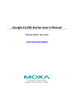
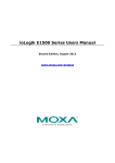
ioLogik R1200 Series Quick Installation Guide Second Edition, April 2014 Overview The ioLogik R1200 comes with 2 RS-485 serial ports, which can be used in one of two ways: 1. 2. For backup or asset monitoring, or As an RS-485 repeater. The ioLogik R1200 has the industry’s first all-in-one design and provides Automatic Field Configuration via USB. No technical background is needed, and maintenance is easy since users can upload a device’s configuration settings and firmware via USB, without needing to take a PC to the field site. Model Selection: ioLogik R1210 R1212 R1214 R1240 R1241 DI 16 8 6 – – DIO Relay – – 8 – – 6 – – – – AI – – – 8 – AO – – – – 4 Package Checklist • • • 1 ioLogik R1200 series remote I/O product Documentation and software CD Quick installation guide (printed) Specifications System Serial IO 2 x RS-485-2W: Data+, Data-, GND (5-contact terminal block) Protection 8 KV ESD, 1 KV surge, 3 KV EFT Protocols Modbus/RTU Power Input 24 VDC nominal, 12 to 48 VDC Wiring I/O cable max. 14 AWG Dimensions 27.8 x 124 x 84 mm (1.09 x 4.88 x 3.31 in) Weight under 200 g Operating Temperature Standard Models: -10 to 75°C (14 to 167°F) Wide Temperature Models: -40 to 85°C (-40 to 185°F) Storage Temperature -40 to 85°C (-40 to 185°F) Ambient Relative 5 to 95% (non-condensing) Humidity Altitude Up to 2000 m Note: Please contact Moxa if you require products guaranteed to function properly at higher altitudes. Standards and UL 508, CE, FCC Class A Certifications Warranty Period 5 years (excluding ioLogik R1214*) Details See www.moxa.com/warranty *Because of the limited lifetime of power relay, products that use this component are covered by a 2-year warranty. Communication Parameters (Initial mode) Parity None, Even, Odd (default = None) Data Bits 8 Stop Bits 1, 2 (default = 1) Flow Control None, XON/XOFF (default = None) Baudrate 1200 to 921.6 kbps (default = 9600) Digital Input Sensor Type NPN, PNP, and Dry contact I/O Mode DI or Event Counter Dry Contact • On: short to GND • Off: open Wet Contact • On: 10 to 30 VDC (DI to COM) • Off: 0 to 3 VDC Isolation 3K VDC or 2K Vrms Counter/Frequency 2.5 kHz, power off storage Digital Output I/O Mode DO or Pulse Output Pulse Wave 0.1 ms / 5 kHz Width/Frequency Over-voltage 45 VDC Protection Over-current Protection 2.6 A (4 channels @650 mA) Expected Life Initial Contact Resistance Pulse Output Analog Input Type Resolution I/O Mode Input Range Accuracy Sampling Rate (all channels) Input Impedance Built-in Resistor for Current Input Analog Output Resolution Output Range Voltage Output Accuracy Load Resistor 100,000 times (Typical) 30 milli-ohms (Max.) 0.3 Hz at rated load Differential input 16 bits Voltage / Current 0 to 10 VDC, 4 to 20 mA ±0.1% FSR @ 25°C ±0.3% FSR @ -10 and 60°C ±0.5% FSR @ -40 and 75°C 12 samples/sec 10M ohms (minimum) 120 ohms 12 bits 0 to 10 VDC, 4 to 20 mA 10 mA (Max.) ±0.1% FSR @ 25°C ±0.3% FSR @ -40 and 75°C • Internal power: 400 ohms • External 24V power: 1000 ohms Installation Power and Networking Connect the +12 to +48 VDC power line to the ioLogik R1200’s terminal block V+ terminal; connect the ground from the power supply to the V- terminal. Connect the ground pin ( ground is available. Over-temperature Shutdown Current Rating Isolation Relay Output Type Contact Rating Inductance Load Resistance Load Breakdown Voltage Relay On/Off Time Initial Insulation Resistance 175°C (typical), 150°C (min.) 200 mA per channel 3K VDC or 2K Vrms Form A (N.O.) relay outputs, 5A 5 A @ 30 VDC, 5 A @ 250 VAC, 5 A @ 110 VAC 2A 5A 500 VAC 1500 ms (Max.) 1G min. @ 500 VDC NOTE For safety reasons, the wires attached to the power should be at least 2 mm (12 gauge) in diameter. P/N: 1802012002011 –1– ) if earth –2– –3– Switch Settings LED Indicators The R1200 series provides Dual/Rep and Run/Initial switch settings to set up the communication mode. Type PWR LED Color Green RDY Green/ Red Duel (Default) Rep Run Initial (Default) Dual RS-485 mode Repeater mode User define communication parameters Initial RS-485 communication parameters P1 Jumper Settings The models with DIO or AI channels require configuring the jumpers inside the enclosure. Remove the screw located on the back panel and open the cover to configure the jumpers. P2 Green/ Amber Green/ Amber LED Action On: Off: Green: Green Blinking: Red: Red Blinking: Green/Red Blinking: Off: Green: Amber: Blinking: Off: Green: Amber: Blinking: Off: System Configuration Power On Power Off System Ready Located System Boot-up Error Firmware upgrade / USB upgrade Safe Mode System NOT Ready Tx Rx Data Transmitting Disconnected Tx Rx Data Transmitting Disconnected ioSearch Utility ioSearch is a search utility that helps users locate an ioLogik R1200 on the local network. The utility can be found in the Document and Software CD Software ioSearch; the latest version can be downloaded from Moxa’s website. Load Factory Default Settings There are three ways to restore the ioLogik R1200 to the factory default settings. 1. 2. 3. Hold the RESET button for 5 seconds. Right click the specified ioLogik in the ioSearch utility and select “Reset to Default.” Select “Load Factory Default” from the web console. Modbus Address Table Please refer to the user’s manual for details of the ioLogik’s Modbus address. I/O Wiring Digital Input/Output (Sink Type) DIO mode configuration is shown to the right (default: DO Mode). Analog mode configuration is shown to the right (default: Voltage Mode). Mounting The ioLogik R1200 is designed with a vertical form factor, and can be used with both DIN-Rail and wall mounting applications. When mounting on a rail, release the bottom mounting kit, install the ioLogik on the rail, and then restore the bottom mounting kit to fix the ioLogik to the rail. When using wall mounting, release both the upper and bottom DIN-Rail kits. Analog Input Relay Output (Form A) www.moxa.com/support The Americas: Europe: Asia-Pacific: China: +1-714-528-6777 (toll-free: 1-888-669-2872) +49-89-3 70 03 99-0 +886-2-8919-1230 +86-21-5258-9955 (toll-free: 800-820-5036) 2014 Moxa Inc., All Rights Reserved –4– –5– –6–