1
1010-1001A Rev 02
COPYRIGHT NOTICE
This manual is a publication of Maple Systems, Inc., and is provided for use by its customers only. The contents of the
manual are copyrighted by Maple Systems, Inc.; reproduction in whole or in part, for use other than in support of Maple
Systems equipment, is prohibited without the specific written permission of Maple Systems.
WARRANTY
Maple Systems warrants each product to be free from electrical and mechanical defects in materials and workmanship for a
period of two years from the date of shipment. This warranty does not apply to defects in the Products caused by abuse,
misuse, accident, casualty, alteration, negligence, repair not authorized by Maple Systems, use on current or voltages other
than specified by Maple Systems, or application or installation not in accordance with published instruction manuals. This
warranty is in lieu of any other warranty either expressed or implied.
Maple Systems’ liability is limited to the repair or replacement of the Product only, and not costs of installation, removal, or
damage to user’s property or other liabilities. If Maple Systems is unable to repair or replace a nonconforming Product, it
may offer a refund of the amount paid to Maple Systems for such Product in full satisfaction of its warranty obligation.
Maximum liability of Maple Systems is the cost of the Product.
Information furnished by Maple Systems, Inc., is believed to be accurate and reliable. However, no responsibility is assumed
by Maple Systems for the use of this information nor for any infringements of patents or other rights of third parties which
may result from its use. No license is granted by implication, or otherwise, under any patent or patent rights of Maple
Systems, Inc. Maple Systems retains the right to revise or change its products and documentation at any time without notice.
IF SERVICE IS REQUIRED
Package the unit in its original packaging container or, if unavailable, any suitable rigid container. If a substitute container is
used, surround the unit with shock absorbing material; damage in shipment is not covered by the warranty. Include a letter
with the unit describing the difficulty and designating a contact person. Send to the following address: Maple Systems, Inc.,
808 134th Street SW, Suite 120, Everett, WA 98204-7333.
Only Products that have been issued a Return Material Authorization (RMA) number from Maple Systems may be returned.
All RMAs must be accompanied with a written purchase order for tracking purposes or, in the case of out-of-warranty
repairs, for repair charges on a time and material basis.
All returns will be tested to verify customer claims of noncompliance with the product warranty. Improper return packaging,
which makes verification impossible, will void the warranty. Products passing the tests will be returned “AS IS” to the
customer.
If noncompliance is verified and is not due to customer abuse or the other exceptions described with product warranty, Maple
Systems will, at its option, repair or replace the Product returned to it, freight prepaid, which fail to comply with the
foregoing warranty, provided Maple Systems is notified of such noncompliance within the two-year warranty period.
APPLICATIONS ASSISTANCE
This manual is designed to provide the necessary information for trouble-free installation and operation of your new Operator
Interface Terminal (OIT). However, if you need assistance, please call Maple Systems at 425-745-3229 or visit our web site
at www.maple-systems.com.
Table of Contents
EZware Support . . . . . . . . . . . . . . . . . . . 1
OIT Models Supported . . . . . . . . . . . 1
PLCs Supported . . . . . . . . . . . . . . . . 1
About Your Documentation . . . . . . . 1
Conventions. . . . . . . . . . . . . . . . . . . 1
What You Need . . . . . . . . . . . . . . . . 2
OIT Basics . . . . . . . . . . . . . . . . . . . . . . . 2
What is a Silver Series OIT? . . . . . . . 4
List of Features. . . . . . . . . . . . . . . . . 5
Chapter 1 - Installation of OITs . . . . . . . . . . . . 7
Before You Begin . . . . . . . . . . . . . . . . . . 7
Unpacking the Unit . . . . . . . . . . . . . 7
Managing Electrostatic Discharge . . . 7
CE Compliance . . . . . . . . . . . . . . . . 7
NEMA Rating . . . . . . . . . . . . . . . . . . 7
Environmental Considerations . . . . . 7
Safety Precautions . . . . . . . . . . . . . . 8
Control Panel Design Guidelines . . . . . . 8
Control Panel Grounding . . . . . . . . . 9
Connect OIT Chassis Ground to
Control Panel. . . . . . . . . . . . . . . . . . 9
Power Supply Selection . . . . . . . . . . 10
Cable Routing and Noise Immunity . 10
Installation. . . . . . . . . . . . . . . . . . . . . . . 11
Connect the OIT to Power . . . . . . . . 11
Connect the OIT to the PLC . . . . . . . 12
Panel Preparation . . . . . . . . . . . . . . 13
Mount the OIT to the Panel . . . . . . . 14
Configuration Wiring . . . . . . . . . . . . . . . 14
Connect the OIT to the PC for
Configuration. . . . . . . . . . . . . . . . . . 15
Factory Configuration. . . . . . . . . . . . . . . 15
EasyBuilder’s Default Text Fonts . . . . 37
Using the EasyASCIIFontMaker. . . . . 37
The EasyBuilder Application . . . . . . . . . . 38
Managing Projects . . . . . . . . . . . . . . 39
Printing Projects . . . . . . . . . . . . . . . . 41
Editing and Creating Screen Objects 42
General Settings . . . . . . . . . . . . . . . 58
Security Settings Configuration. . . . . 64
Restart the OIT Automatically after a Project
is Downloaded . . . . . . . . . . . . . . . . . . . . 69
Automatically Save and Compile the
Project . . . . . . . . . . . . . . . . . . . . . . . . . . 69
Compact Flash . . . . . . . . . . . . . . . . . . . . 69
Connecting Multiple OITs to one PLC . . . 70
Hardware Connection . . . . . . . . . . . . . . 70
Software Connection . . . . . . . . . . . . . . . 71
Sharing Data Between the Master OIT
and Slave OIT . . . . . . . . . . . . . . . . . 71
Connecting Multiple OITs Using the
Ethernet Port . . . . . . . . . . . . . . . . . . 72
Sharing Data Between the Master OIT,
Slave OIT and PLC . . . . . . . . . . . . . . 75
Using the Aux Port . . . . . . . . . . . . . . 76
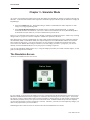
Chapter 3 - Simulator Mode . . . . . . . . . . . . . . 29
The Simulation Screen . . . . . . . . . . . . . . 29
Troubleshooting Tools During
Simulation . . . . . . . . . . . . . . . . . . . . 31
Capturing Simulation Screens to Use as
Documentation . . . . . . . . . . . . . . . . 31
Wiring for Normal Simulation Mode . . . . 32
Chapter 5 - Creating Windows . . . . . . . . . . . . 79
Windows Fundamentals . . . . . . . . . . . . . 79
Opening a Window . . . . . . . . . . . . . 79
Creating a New Window . . . . . . . . . 80
Setting the Window Security Level . . . . . 89
Assigning Underlay Windows . . . . . . 90
How to Display Underlay Windows . . 90
Rules That Apply to Underlay
Windows . . . . . . . . . . . . . . . . . . . . . 90
Deleting a Window . . . . . . . . . . . . . 92
Using Base Windows . . . . . . . . . . . . . . . 92
How to Display Base Windows . . . . . 92
Using the Common Window. . . . . . . . . . 101
Optional settings . . . . . . . . . . . . . . . 103
Changing the Active Common
Window . . . . . . . . . . . . . . . . . . . . . . 106
Using the Fast Selection Window . . . . . . 108
Using the Fast Selection Key. . . . . . . 111
Changing screens using the Fast
Selection window . . . . . . . . . . . . . . . 111
Changing the Fast Selection Window 114
Using the Task Bar . . . . . . . . . . . . . . . . . 117
Using the Window Bar . . . . . . . . . . . 118
General Settings . . . . . . . . . . . . . . . 119
Creating a Message Board . . . . . . . . . . . 120
Optional Parameters . . . . . . . . . . . . 121
Chapter 4 - Using EZware-500 . . . . . . . . . . . . 35
Overview . . . . . . . . . . . . . . . . . . . . . . . . 35
The EasyManager. . . . . . . . . . . . . . . . . . 35
Communications Settings . . . . . . . . . 36
Operating Modes . . . . . . . . . . . . . . . 36
The EasyASCIIFontMaker . . . . . . . . . . . . 37
Chapter 6 - Creating Graphic Objects . . . . . . . 125
Drawing Objects . . . . . . . . . . . . . . . . . . 125
Using the Drawing Tools . . . . . . . . . 125
Using Text . . . . . . . . . . . . . . . . . . . . 128
Predefined Shapes and Bitmaps . . . . . . . 129
Using a Predefined Shape . . . . . . . . 130
Chapter 2 - Creating Your First Project . . . . . . 17
Before You Begin . . . . . . . . . . . . . . . . . . 17
Connecting OIT to Computer . . . . . . . . . 17
Starting EZware-500 . . . . . . . . . . . . . . . 18
Creating a Sample Project . . . . . . . . . . . 19
Setting the System Parameters . . . . . 19
Creating a Startup Window . . . . . . . 20
Creating a Popup Window . . . . . . . . 22
Finishing Up. . . . . . . . . . . . . . . . . . . . . . 26
ii
Silver Series Installation & Operation Manual
Using a Predefined Bitmap . . . . . 131
Graphics Libraries . . . . . . . . . . . . . . . . . 133
What are ‘states’? . . . . . . . . . . . 134
Using Shape Libraries . . . . . . . . 134
Using Bitmap Libraries . . . . . . . . 142
Using Group Libraries . . . . . . . . 147
Chapter 7 - Creating and Using Databases and
Languages . . . . . . . . . . . . . . . . . . . . . . . . . . . . 153
Creating and Using the Tag Library . . . . 153
Importing and Exporting the Tag
Library . . . . . . . . . . . . . . . . . . . . 154
Using the Tag Library . . . . . . . . . 155
Creating the Label Library . . . . . . . . . . . 155
Importing and Exporting the Label
Library . . . . . . . . . . . . . . . . . . . . 158
Using the Label Library. . . . . . . . . . . . . . 158
Using Languages with the Label
Library . . . . . . . . . . . . . . . . . . . . 160
Chapter 8 - Representing Data with Graphics
Objects. . . . . . . . . . . . . . . . . . . . . . . . . . . . . . . 163
Using Internal Data Memory of OIT . . . . 163
Non-volatile Storage of System
Parameters . . . . . . . . . . . . . . . . . . . . . . 169
PLC Settings . . . . . . . . . . . . . . . . 169
General Settings . . . . . . . . . . . . 169
Security Settings. . . . . . . . . . . . . 170
Representing PLC Coil Registers . . . . . . . 170
The Bit Lamp Object. . . . . . . . . . 170
The Set Bit Object . . . . . . . . . . . 173
The Toggle Switch Object . . . . . . 175
Representing PLC Data Registers . . . . . . 177
The Word Lamp Object . . . . . . . 177
The Set Word Object . . . . . . . . . 179
The MultiState Switch Object . . . 182
The Numeric Data Object. . . . . . 184
The Numeric Input Extend Object 187
The ASCII Data Object . . . . . . . . 191
The ASCII Input Extend Object . . 192
The Moving Shape Object . . . . . 194
The Animation Object . . . . . . . . 197
Chapter 9 - Using and Creating Keypads . . . . 201
How to Create a Keypad . . . . . . . . . . . . 201
Displaying and Using a Keypad . . . . . . . 204
Using the Built-In Numeric Keypad in
EasyBuilder . . . . . . . . . . . . . . . . 207
Chapter 10 - Bar Graphs, Meters, and Trends . 213
Creating Bar Graphs . . . . . . . . . . . . . . . 213
Creating Display Meters . . . . . . . . . . . . . 216
Creating Trend Displays . . . . . . . . . . . . . 218
Creating XY Plots . . . . . . . . . . . . . . . . . . 220
Chapter 11 - Capturing Alarms and Events . . . 223
Using Alarms . . . . . . . . . . . . . . . . . . . . . 223
Monitoring Alarms with the Alarm Scan
Object . . . . . . . . . . . . . . . . . . . . . . . . . . 223
Displaying Alarms using the Alarm Display
Object . . . . . . . . . . . . . . . . . . . . . . . . . . 224
1010-1001a Rev 02
Displaying Alarms using the Alarm Bar
Object . . . . . . . . . . . . . . . . . . . . 228
Using Events . . . . . . . . . . . . . . . . . . . . . 230
Monitoring Events With the Event Log
Object . . . . . . . . . . . . . . . . . . . . 230
Displaying Events Using the Event
Display Object . . . . . . . . . . . . . . 232
Using Events for an Alarm History . . . . . 234
Using the Alarm History . . . . . . . 237
Chapter 12 - Data and Recipe Transfer Objects 239
Using the Data Transfer Object . . . . . . . 239
Using the Recipe Transfer Object . . . . . . 240
Creating a Recipe. . . . . . . . . . . . 243
Chapter 13 - Macros . . . . . . . . . . . . . . . . . . . . 245
Using Macros . . . . . . . . . . . . . . . . . . . . 245
Macro Sample and
Implementation . . . . . . . . . . . . 245
Variables, Declarations and Memory
Usage . . . . . . . . . . . . . . . . . . . . . . . . . . 248
Memory Usage: . . . . . . . . . . . . 248
Variable Declarations. . . . . . . . . 248
Variable Initialization . . . . . . . . . 249
Array Initialization . . . . . . . . . . . 249
Reserved Words . . . . . . . . . . . . . 249
Operator . . . . . . . . . . . . . . . . . . 250
Order of Precedence . . . . . . . . . 250
Main Functions and
Sub-functions. . . . . . . . . . . . . . . 250
Local and Global Variables . . . . 251
Creating Variable Arrays . . . . . . 251
Using Macros Within Recipes . . . 251
Using 32-bit Registers Within
Macros. . . . . . . . . . . . . . . . . . . . 252
Using Floating Point Registers Within
Macros. . . . . . . . . . . . . . . . . . . . 253
Statements, Conditions &
Expressions . . . . . . . . . . . . . . . . 253
Function calls and passing parameters
. . . . . . . . . . . . . . . . . . . . . . . . . 255
Reading & Writing External Registers
in a Macro . . . . . . . . . . . . . . . . . 256
Precautions, tips & tricks when using
Macros . . . . . . . . . . . . . . . . . . . 257
Compiler Errors & Error Codes . . . . . . . . 257
Chapter 14 - Using a Printer With the
HMI530T/550T. . . . . . . . . . . . . . . . . . . . . . . . . 261
Configuring the HMI530T/550T for a
Printer . . . . . . . . . . . . . . . . . . . . 261
Printing a Window . . . . . . . . . . . . . . . . . 262
Using a Function Key . . . . . . . . . 262
Using PLC Control Object. . . . . . 262
Using Simulation Mode . . . . . . . 263
Printing a Report . . . . . . . . . . . . 263
Introduction
1
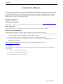
Introduction - Welcome
Welcome to the Maple Systems’ Silver Series of Operator Interface Terminals (OITs). Using graphic OITs has never been
easier. This powerful family of graphics operator interface terminals connects to programmable logic controllers (PLCs) to
provide the human-machine interface in industrial applications. The Silver Series has several features not found in other
graphic OITs. This manual explains the operation of the Silver Series OITs and how to implement the many available
features using the EZware-500 Configuration Software.
EZware Support
OIT Models Supported
For the latest list of Silver Series Models supported by EZware, please visit our website at http://www.maple-systems.com.
PLCs Supported
For the latest list of PLCs and controllers supported by the Silver Series OITs, please visit our website.
About Your Documentation
Maple Systems provides many resources to allow you to get the most out of your Silver Series OIT.
· Silver Series Operation Manual (shipped with EZware-500 as a PDF file) - describes installation, general operation
and features of the Silver Series using EZware-500 configuration software.
· Controller Information Sheets - important information specific to each supported protocol.
· EZware-500 On-line Help - covers the operation of EZware. Always available by clicking Help Topics from the
Help menu in EasyBuilder.
For more information about these and other training sources, visit the Maple Systems web site at:
http://www.maple-systems.com
Conventions
When using EZware-500, there are usually several ways to perform a task. For example, if you want to copy a graphics
object, you can:
· Click the Copy command on the Edit menu.
· Click the Copy button on the Standard toolbar.
· Press the CTRL + C keys on your computer.
1010-1001a, Rev 02
2
Silver Series Installation & Operation Manual
In most cases, we will describe each method when the task is first discussed. The menu method is then used whenever the
task is used in later procedures. Other conventions used in this book are listed in the following table.
Convention
Meaning
Bold
Characters that you must type exactly as they appear. For example, if you are directed to type
a:\setup, you should type all the bold characters exactly as they are printed.
Italic
Placeholders for information you must provide. For example, if you are directed to type filename, you
should type the actual name for a file instead of the word shown in italic type. Italics are also used to
indicate a glossary term.
ALL CAPITALS
Directory names, file names, key names, and acronyms
KEY1+KEY2
A plus sign (+) between key names means to press and hold down the first key while you press the
second key.
click
Refers to clicking the primary mouse button (usually the left mouse button) once.
Double-click
Refers to quickly clicking the primary mouse button (usually the left mouse button) twice.
Right-click
Refers to clicking the secondary mouse button (usually the right mouse button) once. Right-clicking
usually opens shortcut menus.
The following table identifies symbols and margin icons.
Icon
Meaning
4
4
Identifies a procedure.
Indicates a reference to additional information.
Indicates an important note.
What You Need
The following items are needed to configure and operate your OIT.
Configuration Software
EZware-500
Configuration Cable
(OIT to PC) Y-adapter cable1
7431-0098
Personal Computer2
User Provided
Power Cable
6030-0009
3
24VDC Power Supply
User Provided (for details refer to Appendix A: Specifications)
PLC
User Provided
Controller Information Sheet
Maple Systems provides Controller Information Sheets which contain important information specific
to each PLC. Please locate the sheet that corresponds to your PLC on our website.
Communication Cable
(OIT to PLC)
Refer to Maple Systems’ Tech Note 1061 for a list of available cables or build your own using the
cable diagrams available on our web site (www. maple-systems.com).
1Allows
you to connect OIT to PC using RS232 and a PLC that uses RS485 at the same time
2Computer requirements include at least a Pentium 90Mhz PC, 16MB RAM, 10MB available hard disk space, VGA video
controller, Microsoft Windows 95, 98, 2000, or NT, and one available RS-232 serial port.
312-24 VDC power supply needed for the HMI504T.
OIT Basics
Operator Interface Terminals (OITs) provide much more versatility than traditional mechanical control panels. An OIT
allows a plant floor operator to monitor current conditions of a control system and, if necessary, to initiate a change in the
operation of the system. OITs connect to programmable logic controllers (PLCs) typically through the PLC’s serial
communications port. The OIT can be programmed to monitor and/or change current values stored in the data memory of the
PLC.
OITs can have either text-based or graphics-based displays. A text-based OIT can display printable text characters but no
graphics. Some text-based OITs can display text characters in various sizes. A graphics-based OIT can display printable text
1010-1001a, Rev 02
Introduction
3
characters of varying fonts and sizes and graphics shapes such as icons, bitmaps, or pictures. Using pictures instead of words
or characters often greatly simplifies the operation of the OIT, making the OIT much more intuitive to use.
Some OITs use touch screen displays while others use a membrane-style keypad. Membrane-style keyboards are best used in
applications in which the keypad is likely to become dirty. Touch screen displays are placed over the OIT screen thus
providing much more flexibility than typical membrane-style keypads. Because of this, switches can be created on a touch
screen that appear only when needed.
The Maple Systems Silver Series OITs are graphics-based touch screen OITs. Before we get any further into the operation of
these OITs, it is necessary to define some terms that will be used throughout this manual.
Projects
The OIT has two basic segments of internal memory. The code memory contains the information required by the OIT that
controls how it operates such as the features supported and how it communicates to a PLC. The OIT programmer does not
have the ability to change code memory. The project memory pertains to all of the window screens created and any other
features that the OIT programmer can create using the EZware-500 configuration software. Therefore, the term project is
used to designate the file that is sent to the OIT from the EZware-500 software.
Objects
An object is any action that the OIT performs while it is communicating to the PLC. In order to get the operator interface
terminal to ‘do anything’, you must program the OIT with objects. Objects perform actions such as display text or graphics,
write a value to a PLC register, or display an alarm. Objects most often are graphics shapes that are to be displayed on the
OIT screen. For example, a Text Object is used to display text on the OIT. But objects are also used to configure the OIT to
perform some action. For example, a PLC Control Object tells the OIT to continuously monitor a PLC register that is used
by the PLC to request a new window. Some objects can display a graphics shape on the OIT screen and perform some
action. For example, a Toggle Switch Object creates a graphic object on the OIT that when pressed, activates a bit in the
PLC.
Graphics Object
A graphics object is any text, icon, or picture that can be displayed on the OIT. Graphics objects are further defined by how
they are composed or created. A Text Object is a graphics object that displays text on the OIT screen. A Bitmap Object is a
graphics object that displays a bitmap on the OIT screen. Bitmaps are files stored in the OIT to display pictures. A Shape
Object is a graphics object that displays a shape on the OIT screen. Shapes are also files stored in the OIT to display
pictures. Shapes differ from bitmaps in that shapes are stored using a vector-based file format whereas bitmaps use a
pixel-based file format. Each format has its advantages and disadvantages. We will not go into any more detail about bitmap
objects and shape objects until later in this manual. For now, think of them as objects used to display pictures on the OIT
screen. Finally, a Group Object is the most complex type of graphics object. It is a combination of other objects. Briefly, a
group object consists of one or more objects that are ‘grouped’ together and stored as one object. A good example is a
keypad, which is really a combination of several keys each designed to perform a specific task. When grouped together, a
keypad can be stored as a group object for use in other projects or windows.
Windows
A window is a screen that can be displayed on the OIT. Windows can be full-sized to completely cover the OIT display or
partially sized. Any partially sized window is usually referred to as a popup window. Windows can appear on the OIT
display by a request from the PLC or by a press from the touch screen. Windows can be configured to any size. Once a
window is displayed, it can be moved around the OIT display, removed from the display, or minimized to an icon. Windows
can even overlap each other. Each window can display graphics objects and there is no limit to the number of graphics
objects that can be placed on each window. The Silver Series is capable of storing up to 1999 windows , but the actual limit
is determined by the total amount of memory used for the application. A more in-depth discussion of windows is covered in
later chapters. For now, think of windows as screens that can be displayed on the OIT.
1010-1001a, Rev 02
4
Silver Series Installation & Operation Manual
What is a Silver Series OIT?
The Silver Series of OITs by Maple Systems are graphics operator interfaces designed to connect to PLCs in an industrial
environment. The displays are covered with a 4-wire analog resistive touch screen designed for harsh industrial
environments. The touch screen uses the latest in touch screen technology enabling the OIT programmer to create switches
that are very fine in resolution. Unlike many other touch screen OITs on the market, the Silver Series is not limited to a fixed
number of cells in which switches can be created. The OIT programmer can create as many switches of varying sizes and
shapes as he wishes, limited only by the total amount of memory available for the project.
Three LED indicators are provided on the face of the Silver Series OIT to provide instant feedback to the OIT operator of the
current operating condition of the OIT.
LED Indicator
Purpose
PWR LED (yellow)
indicates if power is applied to the OIT
CPU LED (green)
indicates if the OIT is operating correctly
COM LED (red)
indicates communications activity on PLC port
The Silver Series OIT has two serial ports, which provide a connection to a PLC using RS-232 or
RS-485 communications and an RS-232 connection to a computer for programming. The serial ports also provide the ability
to connect multiple OITs in series to a single PLC port! The two serial ports also provide the ability to use the EZware-500
configuration software in Simulation Mode enabling the OIT programmer to test his project on the PC instead of
downloading the project to the OIT.
The Silver Series is powered using +24VDC. The viewing level of the OIT display can be adjusted using a contrast switch
located on the back of the unit, or using Local Bits LB9091 and LB9092 for Contrast Up/Down. Finally, a reset switch is
provided on the back of the OIT to reinitialize the OIT if an operational failure occurs. The Silver Series is designed for
industrial environments and carries a NEMA 4 rating as well as CE compliance for noise immunity and emissions.
The HMI504T will operate at 12 VDC.
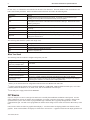
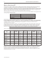
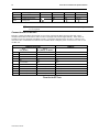
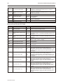
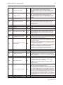
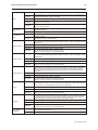
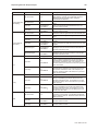
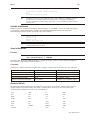
There are currently SEVEN models in the Silver Series.
Brightness
(cdm2)
Contrast
Recipe/RTC
Module
Ethernet &
Compact
Flash
256-color
TFT
300
400:1
No
No
320 x 234
256-color
TFT
500
150:1
Standard
No
5.6"
320 x 234
256-color
TFT
500
150:1
Standard
Yes
HMI530T
7.7"
640 x 480
256-color
TFT
400
250:1
Standard
No
HMI530TE
(Enhanced)
7.7"
640 x 480
256-color
TFT
400
250:1
Standard
Yes
HMI550H
10.4”
640 x 480
256-color
TFT
400
300:1
Standard
No
HMI550HE
(Enhanced)
10.4”
640 x 480
256-color
TFT
400
300:1
Standard
Yes
Display size
Resolution
(pixels)
LCD Type
HMI504T
4.3"
480 x 272
HMI520T
5.6"
HMI520T E
(Enhanced)
Model
Finally, the Silver Series are powered by a 200 MHz Intel XScale processor, making it one of the fastest OITs available on
the market. Even the most complicated graphics can be displayed quickly on the OIT screen. In addition, the OIT uses a
proprietary algorithm to find the most efficient means of extracting data from the PLC. This lowers the amount of
‘bottleneck’ time due to the relatively slow communications baud rate of most PLCs. Therefore, the update rate to gather
information from the PLC is very fast.
1010-1001a, Rev 02
Introduction
5
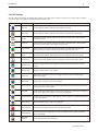
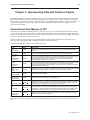
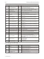
List of Features
The next chapter will guide you through the creation of your first project. Before you proceed, you may wish to read this
brief list of some of the features offered in the Silver Series OIT.
Icon
Name
Description
Bit Lamp
Creates a graphics object to reflect the current status of a PLC bit.
Word Lamp
Creates a graphics object to reflect the current state of a multi-state PLC data register.
Set Bit
Creates a touch screen graphics object that represents a two-state switch. When pressed it
sets/resets a PLC bit.
Set Word
Creates a touch screen graphics object that represents a multi-state switch. When pressed it
can place a constant value in a PLC register or jog the value.
Toggle Switch
Creates a touch screen graphics object that represents a two-state switch changing state
(picture) based upon a PLC bit. When pressed, it can control another PLC bit.
Multi-State
Switch
Creates a multi-state touch screen graphics object that changes state (picture) according to the
value in a PLC data register. When pressed, it sends a value(s) to another PLC register.
Function Key
Creates a touch screen graphics object, which displays a window or edits a PLC register.
Numeric Input
Displays a number stored in a PLC register. The number can be changed using a numeric
keypad.
Numeric Data
Displays a number stored in a PLC register
ASCII Input
Displays ASCII characters stored in a PLC register. Characters can be changed using an
alphanumeric keypad.
ASCII Data
Displays ASCII characters stored in a PLC register
Moving Shapes
Creates a multi-state graphics object, which changes state (picture) and position on the screen
according to a value in a PLC register.
Animation
Creates a multi-state graphics object, which changes state (picture) on the screen according to a
value in a PLC register. The positions on the screen are predefined.
Indirect Window
Configures the OIT to monitor PLC data registers or coils to display for a specific window popup
by a PLC word address
Direct Window
Displays a Window based on a bit in a PLC Register
Alarm Displays
Creates alarms to display alarms sent from the Alarm Scan Object
Trend Displays
Creates a trend graph. Samples data in a single or multiple 16-bit PLC register and plots the
data on a time graph
Bar Graph
Displays
Creates a bar graph with alarm monitoring
1010-1001a, Rev 02
6
1010-1001a, Rev 02
Silver Series Installation & Operation Manual
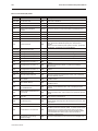
Meter Displays
Creates a scale meter
Alarm Bar
Displays alarms detected by the Alarm Scan Object on a single horizontal scrolling line.
Recipe Transfer
Transfers data to the specified PLC registers (Note: Recipes are not supported by the
HMI504T).
Event Displays
Displays messages according to ‘events’ that occur in the PLC
Alarm Scan
Contains the data for detecting alarm conditions.
System
Message
Customizes the content of system-generated messages.
PLC Control
Configures the OIT to monitor PLC data registers to display full window screens.
Event Log
Monitors and records assigned events
Data Transfer
Configures the OIT to periodically transfer data stored in one set of registers to another set of
registers in the OIT or PLC.
Installation of OITs
7
Chapter 1 - Installation of OITs
Before You Begin
Please read the following for proper handling of your new OIT.
Unpacking the Unit
Carefully unpack the OIT. Please read any instructions or cautions that appear on the shipping container. Check all
material in the container against the enclosed packing list. Maple Systems, Inc. will not accept responsibility for
shortages against the packing list unless notified within 30 days. The equipment and its accessories were inspected
and tested by Maple Systems before shipment; all of the equipment should be in good working order. Examine the
equipment carefully; if any shipping damage is evident, notify the carrier immediately. You are responsible for
claim negotiations with the carrier. Save the shipping container and packing material in case the equipment needs to
be stored, returned to Maple Systems, or transported for any reason.
Managing Electrostatic Discharge
It is best NOT to remove the rear enclosure of the OIT. When the rear part of the enclosure is removed, the circuitry
inside is exposed to possible damage by electrostatic discharge during handling. Minimize the possibility of
electrostatic discharge by:
· Discharging personal static by grounding yourself prior to handling the OIT
· Handling the OIT at a static-free grounded workstation
· Connecting the frame ground (
) connector of the OIT to a clean earth ground
· Placing the OIT in an anti-static bag during transport
CE Compliance
The Silver Series OITs have been tested to conform to European CE requirements per Council Directive
89/336/EEC. The European Union created these requirements to ensure conformity among products traded in those
countries. Specifically, the Silver Series OITs meet or exceed the noise emissions and immunity requirements as set
forth in the EN50081 (Emissions) and EN50082 (Immunity) standards. These products are designed to withstand
electrical noise in harsh industrial environments. They also conform to requirements that limit electrical emissions.
However, this does not guarantee that the products will be totally immune from possible malfunction in cases where
severe electrical noise occurs. Therefore, we strongly recommend that you follow the guidelines outlined in this
chapter for proper wire routing and grounding to insure the proper operation of the Silver Series OIT.
NEMA Rating
The Silver Series OITs are rated for NEMA 4/12 (indoor) or IP65 installations. This means that when the OIT is
properly mounted to a panel or other enclosure, the front enclosure of the OIT will provide protection to the inside
of the panel from splashing water, wind blown dust, rain, or hose-directed water. The OIT must be installed
according to the instructions in this chapter to be properly sealed.
Environmental Considerations
The Silver Series is designed to operate in temperatures from 0-45° C. It is intended for indoor installations and not
designed for outdoor applications. Avoid installing the Silver Series in environments with severe mechanical
vibration or shocks. Do not install the OIT in enclosures with rapid temperature variations or high humidity. Either
will cause condensation of water inside the device and eventual damage to the OIT.
1010-1001a, Rev 02
8
Silver Series Installation & Operation Manual
Safety Precautions
Please observe the following precautions when installing the Silver Series OIT. Failure to comply with these
restrictions could result in loss of life, serious personal injury, or equipment damage.
Warning:
Do not operate the OIT in areas subject to explosion due to flammable gases,
vapors, or dusts.
Warning:
to the OIT.
Do not connect the OIT to an AC power source. You will cause permanent damage
Warning:
Do not attempt to use a DC power supply that does not meet OIT power
requirements. You may cause malfunction or permanent damage to the OIT.
Warning:
Do not power the OIT with a DC power supply used for inductive loads or for input
circuitry to the programmable logic controller. Severe voltage spikes caused by these devices may
damage the OIT.
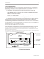
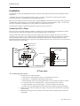
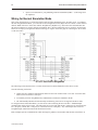
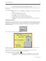
Control Panel Design Guidelines
Pay careful attention to the placement of system components and associated cable routing. These items can
significantly enhance the performance and integrity of your control application.
Control panel is
tied to a reliable
earth ground
Shielded power cable
Ground
strap
HMI530
(rear side)
GND 24V
PRINTER
PC [RS-232]
PLC [RS-485]
PLC [RS-232]
OIT is
grounded to
control panel
Shielded
communication
cable
Quiet ground
OIT
Power
Supply
PLC/Host
Line
Filter
I / O control lines
Ground wires
Quiet ground
(isolated)
Control Panel Example
1010-1001a, Rev 02
Power
line
filter
Installation of OITs
9
Control Panel Grounding
The control panel should be connected to a good, high-integrity earth ground both for safety considerations and
shielding purposes. Maple Systems cannot overemphasize the importance of good grounding. If you fail to use
good grounding procedures during installation, sporadic malfunction of the OIT may occur:
· Connect the OIT’s chassis ground terminal to a reliable earth ground with a low-resistance path.
· Route all earth ground wires that lead from the OIT, the PLC, the power supply, and the line filter to a
central earth ground point such as a barrier strip. This will ensure that no ground current from one device
influences the operation of the other devices.
· Connect the OIT chassis ground terminal to the control panel door using a heavy-gauge short braided cable
or ground wire to minimize resistance.
· Connect the power cable’s shield wire to the OIT’s chassis ground terminal.
· Connect the control panel to earth ground using a copper grounding rod close to the OIT and control panel.
Hinged doors on control panels do not provide a long-term electrical connection to the rest of the enclosure.
Corrosion develops over time and prevents good electrical contract. For this reason, a separate wire braid should be
installed from the hinged control panel to the rest of the enclosure.
For a more in-depth overview of ground wiring techniques, refer to technical note #1027, “OIT Ground Wiring and
Electrical Noise Reduction,” which you can find on our website .
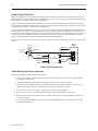
Connect OIT Chassis Ground to Control Panel
To reduce the possibility of electrical interference, connect the chassis ground terminal of the OIT to a clean earth
ground. If the control panel is metal, make sure it is properly grounded. Then connect a short heavy-gauge wire
(#18 AWG) from the chassis ground terminal of the OIT to a mounting bolt on the control panel door. The
mounting bolt must have good electrical contact to the control panel; scrape away any paint that may be covering
the panel to provide a good connection.
If the control panel is made of a non-conductive material, it is essential that you connect the chassis ground terminal
of the OIT to a clean earth ground point located close to the panel.
Control panel
(connected to
earth ground)
HMI530
(rear side)
GND 24V
PRINTER
PC [RS-232]
PLC [RS-485]
PLC [RS-232]
Area on panel
free of paint
Stud or screw
OIT Chassis Ground Connection
1010-1001a, Rev 02
10
Silver Series Installation & Operation Manual
Power Supply Selection
The power supply used to power the OIT should provide an output of +24 VDC 5% measured at the OIT power
terminal block. A 24VDC regulated power supply dedicated to the OIT is required. Refer to the installation guide
that accopanies each OIT for input current requirements.
The power cable for the OIT should be 18AWG, 2-conductor wire with a shield drain wire and protective shield
(foil or braid). The shield drain wire must be connected to earth ground at both ends of the cable. Please refer to the
“Connect the OIT to Power” section for more information.
A power line filter installed at the AC input to the OIT power supply is highly recommended as a safeguard against
conducted RF noise, which is often present on factory power lines. The wires connecting the output of the power
line filter to the power supply should be kept as short as possible to minimize any additional noise pickup. The case
of the power line filter should be connected to a quiet earth ground. The power line filter should have a current
rating of at least 3 Amps with common mode and differential mode attenuation.
Do not use the power supply used to provide power to the OIT to power switching relays, solenoids, or other active
devices.
"Quiet”
ground
To earth
ground
Keep short
Power
Supply
Bus bar
Green
White to
110Vac neutral
Black to
110Vac load (hot)
N
N
AC
G Line Filter
L
L
White
GND
AC
AC
Black
Power Line Filter Connection
Cable Routing and Noise Immunity
Follow these guidelines when routing cable to the OIT:
· Always route the OIT communication cable and the power cable away from any AC voltage or rapidly
switching DC control lines.
· Never bundle the OIT cables together with 120VAC power wires or with relay wiring.
· Try to keep at least 8 inches (20 cm) of separation between the OIT cables and other power wiring. If
voltages greater than 120VAC are used in the system, greater separation is required.
· If the OIT cables must come near AC wiring, make sure they cross at 90 degrees.
· Run AC power wires in a separate grounded conduit to reduce electrical noise interference.
· Keep the cable lengths for the OIT as short as possible. Do not coil excess cable and place it next to AC
powered equipment.
· Cover any equipment used in the enclosure that operates at high frequency or high current levels with a
grounded metal shield.
1010-1001a, Rev 02
Installation of OITs
11
Installation
It is necessary to follow all installation procedures described in this chapter for electrical noise immunity and CE
compliance.
Your Maple Systems OIT is designed to connect easily to your PLC. External rear connectors provide quick
connections for power, communications and programming wiring.
There are two serial ports on the rear of the OIT (except the HMI504T, which has one serial port). Both of these are
D-subminiature 9-pin connectors. Use the female connector for RS-232 communications to a PLC. Use the male
connector for RS-485 communication to a PLC and RS-232 communications to a PC.
Use the supplied separate 3-position terminal block to provide power to the OIT.
Connect the OIT to Power
The power cable for the OIT should be 18AWG, 2-conductor wire with a shield drain wire and protective shield
foil. You may buy cable P/N 6030-0009 by the foot from Maple Systems to make these.
Always run the DC ground wire directly back to the signal return of the power supply. Do not use the chassis
ground wire as your signal return! Maple Systems recommends using an axial ferrite coil (Maple p/n 2531-0001)
with each HMI550 OIT to further reduce the electrical interference that may be conducted on the power lines.
Thread the positive and negative wires of the power cable through the ferrite coil so that the coil is no more than two
inches from the OIT’s power input.
Shield wire (bare)
Black wire (-)
Red wire (+)
Control
panel
(-) (+)
GND 24V
OIT
(rear side)
24Vdc
power supply
Ferrite coil
120Vac
Shield drain
Black
Red
FG
DC Output -V (Gnd)
DC Output +V (+24V)
OIT Power Inputs
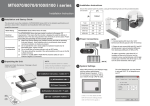
4To connect the OIT to power:
1. Connect the power cable to the OIT
a. Strip the power cable shield to expose 2” of the black and red wires.
b. Strip about ¼” of insulation from the black and red wires.
c. Thread the black and red wires through the ferrite core. The shield wire must be outside.
d. Connect the red wire to the DC positive (+) input of the OIT power terminal.
e. Connect the black wire to the DC negative (-) input of the OIT power terminal.
f. Connect the power cable shield wire to the OIT power terminal’s chassis ground input.
2. Route the power cable to the OIT power supply. The power cable should not be any longer
than necessary.
3. Install the power supply wires as follows (with colors shown for Maple Systems cable P/N
6030-0009):
1010-1001a, Rev 02
12
Silver Series Installation & Operation Manual
Color
Power Supply
HMI504T
HMI520T
HMI530T
HMI550T
Red
+Output/+24 Vdc
+
+ 24V
24V
+DC24V
Black
-Output/+24 Vdc return
-
GND
GND
-DC 24V
Shield
Case ground
FG
The power connector on the Silver Series is a terminal block with wire clamps. Lugs
are not required.
Connect the OIT to the PLC
Each PLC supported by Maple Systems has its own wiring requirements. Maple Systems offers OIT-to-PLC
communication cables for most PLCs that are built to any length and tested for high reliability. Most cables are
available for next-day shipment from Maple Systems. Components and instructions necessary to construct your
own OIT-to-PLC communications cables are also available. Refer to Maple Systems’ Technical Note 1061 or visit
our Web site.
HMI520T/530T/550T
Port 1
PLC (RS-232)
HMI504T
Port 2
PLC (RS485) / PC (RS232)
Pin #
Function
Function
Function
1
Aux-TXD
RXD-
RXD-
2
TXD
RXD+
RXD+
3
RXD
TXD-
TXD-
4
(no connection)
TXD+
TXD+
5
GND
GND
GND
6
Aux-RXD
(no connection)
TXD (PLC)
7
(no connection)
TXD
TXD (PC)
8
(no connection)
RXD
RXD (PC)
9
(no connection)
(no connection)
RXD (PLC)
Pinout for the OIT Ports
1010-1001a, Rev 02
Installation of OITs
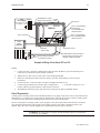
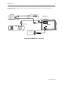
13
OIT
Output
Power Supply
Shielded Power Cable, Control
Maple P/N 6030-0009 Panel
Printer port
DC Output +V (+24V)
DC Output -V (Gnd)
FG
Port 2, PLC[RS-485]/
PC[RS-232],
has a shielded male
DE9P connector
HMI530
Enhanced
models only
Power connector
Port 1, PLC[RS-232],
has a shielded female
DE9S connector
Port 2 Port 1
GND 24V
PRINTER
PC [RS-232]
PLC [RS-485]
PLC [RS-232]
Printer
(Epson
Compatible)
Standard
printer cable
PLC/
Host
Earth
GND
Attach earth ground wire
(if included on cable)
Tighten all screws
Communication cable specific for
the PLC/Host; twisted pair, foil
shielded, 28AWG minimum
Example of Wiring a Silver Series OIT to a PLC
STEPS:
1.
Connect the “OIT” end of the communication cable into either the RS-232 port or the RS-485 port as
required for your application (OIT housing is marked).
2.
Tighten the two cable screws at each end to ensure shield ground path.
3.
Route the communication cable to the PLC. Refer to the “OIT Cable Routing” section for more
information.
4.
Connect the “PLC” end of the cable to the PLC and tighten the cable screws.
5.
Connect the green shield wire from the cable to earth ground (
present, make the ground connection inside the PLC connector.
6.
The HMI530T/550T has a printer port and can be connected to an Epson compatible printer.
) on the PLC. If this wire is not
Panel Preparation
A metal panel or mounting surface with a minimum thickness of 15 gauge (0.059 inch/3.3mm) if cold-rolled steel or
hardened steel, or 10 gauge (0.101 inch/2.6mm) if aluminum alloy (6061-T6 preferred) is required. Thinner panels
or surfaces may bow between the mounting clamps and not form a seal with the gasket.
The area of the panel or mounting surface where the gasket comes into contact must be flat and free of scratches,
pits, and other features that prevent the gasket from sealing properly. If the panel or mounting surface is not
uniform, thick, flat, stiff, or smooth enough, then a sealant such as silicone may be required.
WARNING: The OIT requires a stiff, flat, smooth mounting surface free of blemishes
to seal properly to NEMA 4.
1010-1001a, Rev 02
14
Silver Series Installation & Operation Manual
Clean and deburr the panel cutout before the OIT is installed.
Mount the OIT to the Panel
Ends of screws must not
protrude from the clamp
Tighten all screw clamps until
they are uniformly snug
Panel
Panel
Hold the OIT against
the panel until all screw
clamps are in position
Screw clamp locking
tabs go through the
slots
Screw Clamp Placement
Clamps Tightened
Installing Screws on the OIT
Position 4 screw clamps
(2 each side)
Panel
STEPS:
1. Prepare the screw clamps by positioning the metal brackets at the midpoints of the screws. Position the
screws so that the ends don’t protrude from the plastic portions.
2. Set the OIT in the panel cutout and hold it in place until all clamps are in position.
3. Tighten the screw clamps until all are uniformly snug.
CAUTION: Do not over-tighten the screws beyond snugness, or you may damage the housing.
REINSTALLATION: Because the gasket will take a “set” to the panel, be sure to reinstall the OIT to the same
panel cutout when a NEMA 4 seal is required. For best results, also replace the gasket itself.
Configuration Wiring
The OIT must be configured for a particular protocol before use. The EZware-500 software (used on a PC with
Windows 95 or higher) is used for configuring the OIT. For detailed instructions on installing and using the
software, please refer to the software documentation section of this manual.
1010-1001a, Rev 02
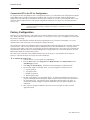
Installation of OITs
15
Connect the OIT to the PC for Configuration
To configure the OIT using Maple System’s configuration software, you will need the OIT Configuration Y-adapter
Cable, Maple P/N 7431-0098. Connect the end marked “OIT” into Port 2 on the OIT, marked “PLC[RS-485]/
PC[RS-232], and connect the end marked PC into the proper COM port on your PC. The end marked “PLC” is not
used here. See the figure below for serial port pin assignments and the next two figures for connecting the Silver
series to a PC.
Many PCs no longer support RS232 serial ports. If our PC has a USB port, then you
can download projects using a USB to serial adapter, available at your local
electronics store.
Factory Configuration
Each OIT arrives from the factory with a demo project file that illustrates some of the most popular features of the
OIT. Please follow the directions enclosed in Chapter 2, Creating Your First Project, to configure your OIT for the
PLC that you are using.
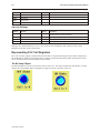
Each OIT has a potentiometer located on the back for adjusting the level of contrast on the display. It is set for
optimum clarity at the factory but you can change the setting if necessary.
The OIT also has a black reset pushbutton and a four position DIP switch located through an access hole on the back
of the enclosure. The reset switch can be used to reinitialize the OIT if the OIT malfunctions. Only Dip switch 1
and 2 have functionality. Dip switch 1 puts the OIT into Touch Calibration mode. Dip switch 2 forces the OIT into
download mode, and needs to be set for downloading from a Compact Flash card. For normal operation, all of the
DIP switches should be set to the OFF position.
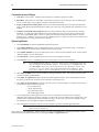
The touch screen of the OIT is fully calibrated before it leaves the factory so you shouldn’t need to adjust it.
However, with time the touch screen may need to be recalibrated.
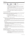
4To calibrate the touch screen
1. Connect the OIT to your computer for programming.
2. From the Start menu, click Programs, then Maple Systems, then EZware-500, then the
EasyManager program.
3. Click Jump To Touch Adjust. The OIT screen should change to calibration mode.
4. After the OIT displays a crosshair cursor, you are prompted to touch the cursor for:
a. Top left position
b. Top right position
c. Bottom left position
d. Bottom right position
5. The OIT screen displays two rectangular objects. To determine whether the touch screen is
properly calibrated, place and hold your finger somewhere on the touch screen other than on
the rectangular spots. The crosshair cursor should appear directly under your finger. If
needed, press the left rectangle to repeat the calibration. Press the right rectangle to end
calibration.
6. Once you have completed calibration, press the touch screen again to return to normal
application mode.
1010-1001a, Rev 02
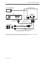
16
Silver Series Installation & Operation Manual
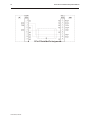
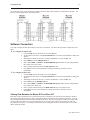
OIT to PC Serial Port Pin Assignments
1010-1001a, Rev 02
Creating Your First Project
17
Chapter 2 - Creating Your First Project
Often the best way to learn about new software is to just jump right in. This chapter will step you through the
process of installing the EZware-500 configuration software and then using the software to create a sample project
that can be downloaded to your OIT. We won’t go into much detail as to how each feature works. The purpose of
this chapter is only to provide you with an overview of the process of creating a functional OIT that can
communicate to a PLC. For our sample project, we will configure the OIT using the MemoryMap_Master protocol
but you may feel free to select whichever protocol driver you intend to use.
By the end of this chapter, you should be able to:
· Install EZware-500 configuration software.
· Create a sample project with two windows and several graphics objects.
· Save a project, compile a project and download the project to the OIT.
· Verify that the OIT is functioning properly.
Before You Begin
Before you install EZware-500, make sure your computer meets the following minimum system requirements:
· Pentium-based 90MHz or higher processor
· 16 MB of RAM (more memory improves performance)
· 10 MB available hard disk space
· VGA or higher-resolution monitor set for 256 color 800x600 pixel mode
· Microsoft Mouse or compatible pointing device
· One available RS-232 port
· Microsoft Windows 95, 98, NT, XP or higher
Connecting OIT to Computer
Before you start your first project, the OIT should be connected to the computer so that the project can be
downloaded after creating it. You should also connect the PLC that you are using to the OIT so that you can test the
operation of the OIT after you have finished creating this sample project.
4To connect your OIT to the computer
1.
2.
3.
Connect a +24VDC power supply to the OIT.
Connect the Y-adapter programming cable (Maple P/N 7431-0098) to the computer and OIT.
• Connect the end marked OIT to the OIT port labeled PC[RS-232].
• Connect the end marked PC to the COM port of the computer.
Apply power to the OIT.
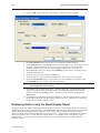
4Changing the PC COM Port used by EZware-500
1.
2.
3.
4.
5.
6.
7.
EZware-500 is initially configured to use Com Port 2:
In Windows, click the Start button.
Select Programs.
Select EZware500.
Select EasyManager.
In the top left drop-down list box, select COM 1.
Choose EXIT.
1010-1001a, Rev 02
18
Silver Series Installation & Operation Manual
4To connect your PLC to the OIT
1.
2.
3.
4.
Maple Systems produces PLC communications cables, which will connect the OIT to most of
the PLCs available. The cables can be manufactured to any length you may require. A listing
of all the PLC cables Maple Systems offers can be found on our website.
If you have decided to make your own cable, make sure that it is wired correctly for your
particular PLC. Maple Systems provides cable wiring diagrams to guide you through the
construction of your cable. These can also be found on our website.
Connect the PLC communications cable from the serial port on your PLC to the appropriate
serial port on your OIT.
• If you are using RS-232 communications, then connect the OIT end of the cable to the OIT
port labeled PLC[RS-232].
• If you are using RS-485 communications, then connect the OIT end of the cable to the OIT
port labeled PLC[RS-485]. If you wish to use the Y-adapter programming cable, then
connect to the cable end that is marked PLC.
Apply power to the PLC. The Silver Series OIT is programmed at the factory with a sample
demo that shows some features of the OIT. The OIT should display a sample startup screen.
The OIT will now accept a new project from EZware-500.
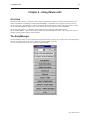
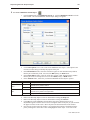
Starting EZware-500
Before you can create a sample project, you must start the configuration software. The EZware-500 software has
three main applications:
· EasyBuilder – used to create the project downloaded to the OIT.
· EasyManager - used to place the OIT into different operating modes.
· EasyASCIIFontMaker - used to edit the text fonts that display characters on the OIT.
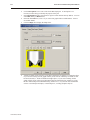
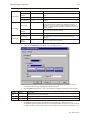
4To start the EZware-500 software
1.
2.
3.
4.
5.
6.
7.
8.
9.
1010-1001a, Rev 02
From the Windows Task Bar, click the Start button, point to Programs, and then click the
EZware-500 folder.
Click EasyManager to start the EasyManager application.
Select the appropriate COM port on your computer.
Select a baud rate of 38400.
After you have successfully downloaded a project to the OIT using this baud rate, try
using 115200 to decrease the required download time.
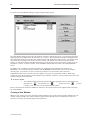
Click Project Download/Upload.
Click Complete Download/Upload.
After you have downloaded your first project to the OIT, you can switch to Partial
Download/Upload to decrease the required download time.
On the EasyManager dialog box, click EasyBuilder.
The Welcome to EasyBuilder dialog box appears. Select the correct OIT model.
Click OK to display the main screen of EasyBuilder.
If the main screen of EasyBuilder is displayed after you click EasyBuilder from the
EasyManager dialog box, select the correct model of OIT by clicking New from the File
menu.
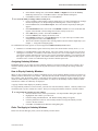
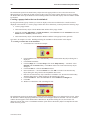
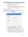
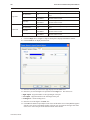
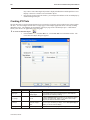
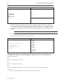
Creating Your First Project
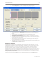
19
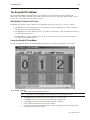
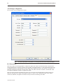
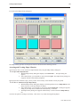
The following illustration shows the various sections of EasyBuilder.
Menu selections
Standard toolbar
Manager
toolbar
Draw toolbar
State toolbar
Work area
Part1 toolbar
Part2 toolbar
Creating a Sample Project
This section walks you through the creation of an EasyBuilder project named EBPrj1. Once downloaded to the OIT,
this basic configuration allows the OIT to connect to the PLC, display a startup screen, and display a screen
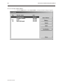
containing one PLC register monitor when a switch on the startup screen is pressed.
Although we strongly recommend that you perform the following steps to create this sample project, the project is
already included in your EasyBuilder software with the following filenames:
HMI504T.EPJ
-sample project for the HMI504T
HMI520T.EPJ
-sample project for the HMI520T
HMI530T.EPJ
-sample project for the HMI530
HMI550T.EPJ
-sample project for the HMI550H
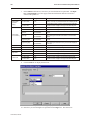
Setting the System Parameters
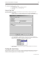
Whenever you begin a new project, you should always set the system parameters before you create any windows.
System parameters determine the basic operating conditions of the OIT such as what type of PLC it is connecting to.
1010-1001a, Rev 02
20
Silver Series Installation & Operation Manual
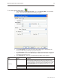
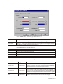
4To edit the System Parameters
1.
2.
3.
4.
5.
6.
7.
8.
9.
10.
11.
12.
13.
14.
15.
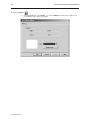
16.
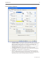
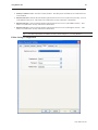
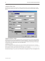
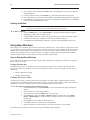
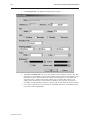
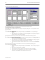
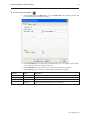
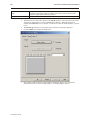
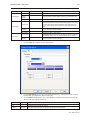
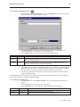
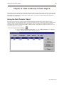
Click the Edit menu on the main screen of EasyBuilder.
At the bottom of the menu, click System Parameters. The Set System Parameters dialog box
appears.
The dialog box has six tabs: PLC, General, Indicator, Security, Editor and Hardware. Select
the PLC tab.
Select the PLC that you are using or MemoryMap_Master from the PLC type pull-down
box.
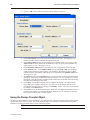
Select RS485 from the Serial port I/F box.
Select 8 bits from the Data bits box.
Select 1 bit from the Stop bits box.
Select 19200 from the Baud rate box.
Select Odd from the Parity box.
Select 0 for the OIT station No. and PLC station No. Boxes.
Select Disable from the Multiple OIT box.
Select 3.0 from the PLC time out constant box.
Select 0 from the PLC block pack box.
Now click on the General tab.
Select 10 for the Startup window No. Box.
Click OK to return to the EasyBuilder main screen.
The communications parameters selected above were selected at random. Please enter
the PLC type and communications parameters that match your PLC. For more
information, consult your PLC operations manual or Maple Systems Controller
Information Sheets available on our website at www.maple-systems.com .
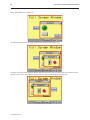
Creating a Startup Window
We will configure Window #10 as the startup screen. The OIT can store up to 1999 predefined windows but
screens 0-9 are reserved. Therefore, the first window screen that is available for configuration is Window #10. By
default, this is the startup screen when you begin a new project. This section will show how to place text in the
window and how to create two function keys that will open and close Window #11.
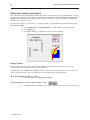
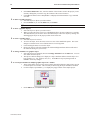
4To place text on Window#10
1.
2.
3.
4.
5.
6.
7.
8.
From the Draw menu, click Text. The Create Text Object dialog box appears.
Click the pull down box from the Color box. The Color dialog box appears.
Click on the white color box, then click OK. The color box should reflect the color that you
have chosen.
Select 16 in the Font box.
Select Left in the Align box.
Double-click the word ‘text’ in the Content box and type “This is the Startup Screen!.”
Click OK.
On the main screen of EasyBuilder, you will see a white rectangle outline that is attached to
your cursor in the work area. This represents the text box just created. Center the rectangle
somewhere on the top third portion of the work area and then click. The text box “This is the
Startup Screen!” should appear.
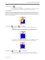
4To create a function key on Window#10
1.
2.
3.
4.
5.
6.
1010-1001a, Rev 02
From the Parts menu, click Function Key. The Create Function Key Object dialog box
appears.
Type On Button in the Description box.
Click Popup Window.
Type 11 in the Window No. Box.
Click the Shape tab.
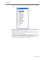
Click Use shape, then click Shape library. The Shape Library dialog box appears.
Creating Your First Project
7.
8.
9.
10.
11.
12.
13.
14.
15.
16.
17.
18.
19.
20.
21.
22.
23.
21
Click button1 in the Shape library box.
Scroll through the selections to selection 23. Click the shape, then click OK. The shape
should appear in the Shape tab.
Click the Label tab.
Click the pull down box from the Color box. The Color dialog box appears.
Click on the black color box, then click OK. The color box should reflect what you have
chosen.
Select 16 in the Font box.
Select Left in the Align box.
Type ON in the Content box.
Click the Use Label box.
Click OK.
On the main screen of EasyBuilder, you will see a white square outline that is attached to your
cursor in the work area. This represents the function key just created. Center the square
somewhere on the bottom left portion of the work area and then click. The function key
should appear.
Double-click on the function key. The Function Key Object’s Attribute box appears.
Click on the Profile tab.
Enter 47 for the X position. Enter 168 for the Y position.
Enter 62 for the Width. Enter 49 for the Height.
Click OK.
On the main screen of EasyBuilder, you should see the function key that you just created
move and/or change size. This function key is used to display Window #11.
4To create a second function key on Window#10
1.
We could create the second function key by repeating the steps for the first function key.
Instead, however, we will take advantage of the first function key and copy it.
2. Click the first function key to highlight it.
3. From the Edit menu, click Copy.
4. From the Edit menu, click Paste. A copy of the function key appears in the upper left corner
of the work area. Deselect the function key by clicking on any blank space in the work area.
5. Double-click on the second function key. The Function Key’s Object Attribute dialog box
appears.
6. In the General tab section, change the Description to Off Button.
7. Click on Change Window. Enter 10 for Window number
8. Click on the Label tab. Type OFF in the Content box.
9. Click on the Profile tab.
10. Enter 196 for the X position. Enter 168 for the Y position.
11. Click OK.
12. On the main screen of EasyBuilder, you should see the second function key that you just
created move to the lower right hand side of the work area. This function key is used to close
Window #11.
1010-1001a, Rev 02
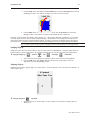
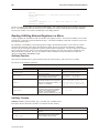
22
Silver Series Installation & Operation Manual
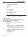
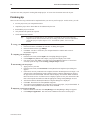
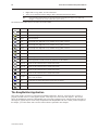
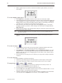
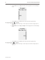
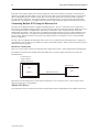
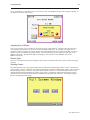
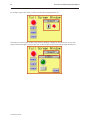
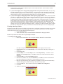
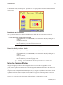
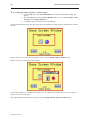
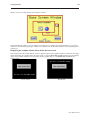
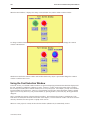
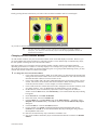
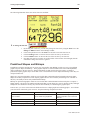
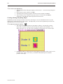
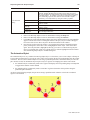
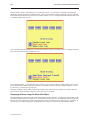
You have finished configuring your first window. It should look something like the picture below:
Creating a Popup Window
We will configure Window #11 as a popup window. Up to six popup windows can be displayed on a full screen
window. The windows may overlap each other or may be minimized to an icon. This section will show how to
create a scale and a numeric register that displays the current value of the scale. You will also create an increment
and decrement key to change the value in the scale meter.
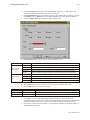
4To create Window#11
1.
2.
3.
4.
5.
6.
7.
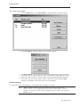
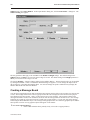
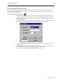
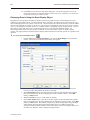
From the Window menu, click Open Window. The Open Window dialog box appears.
Click New Window. The Select Window Style dialog box appears.
Click Base Window. The Window Setting dialog box appears.
Enter 79 for the X position. Enter 58 for the Y position.
Enter 160 for the Width. Enter 120 for the Height.
Click the pull down box from the Background Color box. The Color dialog box appears.
Click on the white color box, then click OK. The color box should reflect the color that you
have chosen.
8. Click OK.
9. Select Window_11 in the Open Window dialog box.
10. Click Open. The main screen of EasyBuilder should reappear with Window #11 displayed in
the work area.
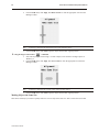
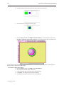
4To create a rectangle on Window#11
1.
2.
3.
4.
From the Draw menu, click Rectangle. The Attributes dialog box appears.
Click on Interior Filled.
Click the pull down box from the Interior box. The Color dialog box appears.
Click on the white color box, then click OK. The color in the Interior box should reflect the
color that you have chosen.
5. Click on an area somewhere inside Window #11. Create a rectangular shape by moving the
mouse cursor. Click again to permanently create the rectangle.
6. From the Edit menu, click Select.
7. Double-click somewhere on the rectangle. The Rectangle Object’s Attribute dialog box
appears.
8. Click the Profile tab.
9. Enter 48 for the X position. Enter 13 for the Y position.
10. Enter 61 for the Width. Enter 36 for the Height.
11. Click OK.
1010-1001a, Rev 02
Creating Your First Project
23
12. On the main screen of EasyBuilder, you should see the rectangle that you just created move
and/or change size. This rectangle is used as a backdrop to the scale meter.
4To create scale lines on Window#11
1.
2.
From the Draw menu, click Scale.
Click on an area somewhere inside Window #11. Create a scale shape by moving the mouse
cursor. Click again to permanently create the scale lines.
3. From the Edit menu, click Select.
4. Double-click somewhere on the scale lines. The Scale Object’s Attribute dialog box appears.
5. In the Scale Style box, click Up.
6. Type 10 in the Division box.
7. Type 8 in the Meter length box.
8. Click on the Profile tab.
9. Enter 51 for the X position. Enter 16 for the Y position.
10. Enter 56 for the Width. Enter 28 for the Height.
11. Click OK.
12. On the main screen of EasyBuilder, you should see the scale that you just created move
and/or change size. This scale should be enclosed by the rectangle.
4To create a meter display on Window#11
1.
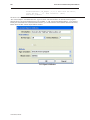
From the Parts menu, click Meter Display. The Create Meter Display Object dialog box
appears.
2. Type Meter Display in the Description box.
3. Click the Meter Display tab.
4. In the Style 2 Indicator box, click Up half.
5. In the Value Span box, enter 100.
6. Click OK.
7. On the main screen of EasyBuilder, you will see a white square outline that is attached to your
cursor in the work area. This represents the meter display just created. Click to place the
meter display in Window #11.
8. Double-click on the meter display. The Meter Display Object’s Attribute dialog box appears.
9. Click on the Profile tab.
10. Enter 51 for the X position. Enter 16 for the Y position.
11. Enter 56 for the Width. Enter 28 for the Height.
12. Click OK.
1010-1001a, Rev 02
24
Silver Series Installation & Operation Manual
13. On the main screen of EasyBuilder, you should see the scaled meter display that you just
created move and/or change size. The scaled meter display is now complete.
4To create a numeric register on Window#11
1.
2.
3.
4.
From the Parts menu, click Numeric Data. The Create Numeric Data Object dialog box
appears.
Type Numeric Data in the Description box.
Click OK.
On the main screen of EasyBuilder, you will see a white rectangle outline that is attached to
your cursor in the work area. This represents the numeric register just created. Click to place
the numeric register on Window #11 somewhere underneath the scale meter. Four pound
signs “####” should appear.
4To create an increment key on Window#11
1.
2.
3.
4.
5.
6.
7.
8.
9.
10.
11.
12.
13.
14.
15.
16.
17.
18.
1010-1001a, Rev 02
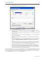
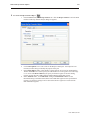
From the Parts menu, click Set Word. The Create Set Word Object dialog box appears.
Type Increment Button in the Description box.
Click on the pull down box of the Set Style Attribute and select JOG++.
Enter 1 in the Inc. value box.
Click on the pull down box of JOG Delay and select 0.5 second.
Enter 100 in the Attribute Upper limit box.
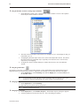
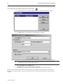
Click the Shape tab.
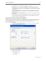
Click Use shape, then click Shape library. The Shape Library dialog box appears.
Click Select Lib… The Open dialog box appears.
Select button3.slb from the list of shape libraries. Then click Open.
Click button3 in the Shape library box.
Scroll through the selections to selection 21. Click the shape, then click OK. The shape
should appear in the Shape tab.
Click OK.
On the main screen of EasyBuilder, you will see a white square outline that is attached to your
cursor in the work area. This represents the increment key just created. Click to place the
increment key on Window #11.
Double-click on the increment key. The Set Word Object’s Attribute dialog box appears.
Click on the Profile tab.
Enter 19 for the X position. Enter 74 for the Y position.
Enter 31 for the Width. Enter 29 for the Height and click OK.
Creating Your First Project
25
19. On the main screen of EasyBuilder, you should see the increment key that you just created
move and/or change size. The increment key is now complete.
4To create a decrement key on Window#11
1.
2.
3.
4.
5.
6.
7.
8.
9.
10.
11.
12.
13.
14.
15.
As with the second function key of Window #10, we are going to create the decrement key by
copying the increment key and then making changes to the attributes.
Click the increment key to highlight it.
From the Edit menu, click Copy.
From the Edit menu, click Paste. A copy of the increment key appears in the upper left
corner of the work area. Deselect the increment key by clicking on any blank space in the
work area.
Double-click on the second increment key. The Set Word Object’s Attribute dialog box
appears.
In the General tab section, change the Description to Decrement Button.
Click on the pull down box of the Set Style Attribute and select JOG—.
Enter 0 in the Attribute Bottom limit box.
Click the Shape tab.
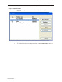
Click Shape library. The Shape Library dialog box appears.
Scroll through the selections to selection 22. Click the shape, then click OK. The shape
should appear in the Shape tab.
Click on the Profile tab.
Enter 105 for the X position. Enter 74 for the Y position.
Click OK.
On the main screen of EasyBuilder, you should see the decrement key that you just created
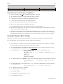
move to the lower right hand side of the work area.
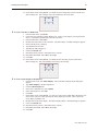
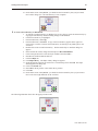
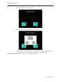
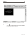
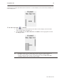
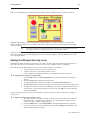
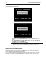
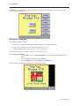
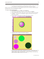
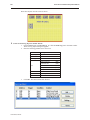
The following illustration shows how the popup window looks:
1010-1001a, Rev 02
26
Silver Series Installation & Operation Manual
You have now done your part in creating this sample project. It is now time for EZware-500 to do its part.
Finishing Up
There are still a few steps, which must be completed before you can test your first project. In this section, you will:
· save the project onto your computer hard drive
· compile the project into a format that can be understood by the OIT
· download the project to the OIT
· verify that the OIT operates as expected
· exit the EZware-500 software
If you haven’t already done so, now would be a good time to connect the OIT to the
computer and to connect the PLC that you are using to the OIT. For more information,
consult the first part of this chapter or see “Installation of OITs” later on in this
manual.
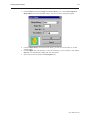
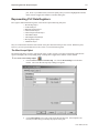
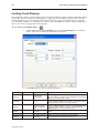
4Saving your first project
1.
2.
3.
From the File menu, click Save As. The Save As dialog box appears.
In the File name text box, type EBPrj1.
Click Save. The file is saved onto your computer hard drive and the main screen of
EasyBuilder reappears.
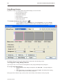
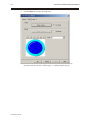
4Compiling your first project
1.
2.
3.
From the Tools menu, click Compile. The Compiling dialog box appears.
Click Compile. EasyBuilder will compile your project and display error results.
If no errors occur, click Close. The main screen of EasyBuilder reappears. If errors have
occurred, repeat the steps in the Creating a Sample Project section.
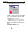
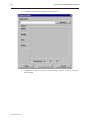
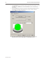
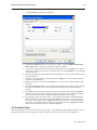
4Downloading your first project
1.
2.
3.
4.
5.
6.
Apply power to your OIT.
From the Tools menu, click Download. The EasyDownload Complete Project dialog box
appears.
If the OIT is correctly connected to the computer, then the download process will begin. You
will notice that a horizontal bar graph is displayed on the computer indicating how much of
the project has been downloaded. The OIT will also display several Write Flash commands
that scroll on the screen. If a timeout error is displayed, please review your connection of the
OIT to the computer and make sure that the appropriate settings in EasyManager are used.
After the download is finished, the Mission Complete dialog box is displayed.
Click OK. The main screen of EasyBuilder reappears.
You will now use EasyManager to get the OIT to execute the project you just downloaded. If
you want to exit EasyBuilder, from the File menu click Exit.
4Displaying your project on the OIT
1.
2.
1010-1001a, Rev 02
From the Windows Task Bar, click EasyManager. The EasyManager dialog box appears.
Click Jump To Application. This will send a command to the OIT to run the project.
Creating Your First Project
27
3.
The OIT should display the following screen.
4.
Press the ON function key to display the popup window.
5.
Press the increment and decrement keys on the OIT to see the value in the data register and
scale meter change. Press the OFF function key to remove the popup window.
CONGRATULATIONS. You have completed your first EZware-500 project.
1010-1001a, Rev 02
28
1010-1001a, Rev 02
Silver Series Installation & Operation Manual
Simulator Mode
29
Chapter 3 - Simulator Mode
As you saw from creating the sample project in the last chapter, downloading any changes you make to the OIT can
take time. To decrease the amount of time required to download a project to the OIT you can make these changes in
EasyManager:
· Select the 115200 baud rate. The default setting of 38400 is recommended for older computers or when
using a very long programming cable.
· Select Partial Download/Upload. The default setting is Complete Download/Upload. A complete
download should be used whenever you receive a later version of EZware-500 or any Boot ROM updates.
It should also be used whenever you select a different PLC protocol driver.
However, even with these improvements, it may still take 1-2 minutes to download a project. A better way of testing
changes made to a project is to use the computer to simulate the operation of the OIT.
This chapter shows you how to dramatically save time when creating and testing a project by putting the computer
into Simulation Mode. In Simulation Mode, the computer displays a screen that simulates what is seen when the
OIT executes the project file. You can use the mouse on your computer to simulate the operation of the touch
screen on the OIT. Rather than waiting two minutes to test each change you make to your project, you can now
instantly switch to Simulation Mode to see if your project is working as expected.
You can enter Simulation Mode in three ways. Using the sample project that you created in the last chapter, we will
guide you through the three methods.
The Simulation Screen
All modes of simulation use the same screen.
For our example, we are showing the sample project as it would appear after the ON function key has been pressed.
When the Simulation Mode screen first appears, it will always show the startup screen of the project. You can test
any objects you have created which require touch screen input by clicking on them. In this example, clicking on the
increment key simulates the key as it is pressed on the touch screen. Simulation Mode always uses the compiled
version of the project that you have created (the *.eob file). Therefore, you must save and compile any changes you
make to the project before you can simulate it.
Simulating the OIT is done in on-line or off-line mode. On-line simulation has two modes:
1010-1001a, Rev 02
30
Silver Series Installation & Operation Manual
‘Normal’ mode requires that the OIT be connected to the computer and that the PLC be connected to the OIT.
‘Direct’ mode requires only that the PC be connected to the PLC. Please note the following:
· Maple Systems’ standard communication cables will not work in Direct mode. The ‘OIT’ end of the cable
must be wired for the PC’s serial port.
· To simulate protocols using RS422/485, an RS422/485 card must be installed in the PC.
· The Allen Bradley DH485 and Telemecanique UniTelWay protocols are not supported in Direct mode.
The On-Line simulation mode is selected in EasyManager, by checking or unchecking the Direct Online-Simulator
box. Whether started from EasyBuilder or EasyManager, the Online-Simulator will operate in the mode selected by
the Direct Online-Simulator box.
On-line simulation is most useful when a project is near completion and you need to test the interaction of the
project with the PLC. It is also very convenient when making minor changes to a project because these changes can
be instantly checked for operation. When ‘normal’ on-line simulation is used, the computer interrogates the PLC
through the OIT to access any data required. When ‘direct’ on-line simulation is used, the computer interrogates the
PLC directly.
Off-line simulation does not require any connection to the OIT. Because of this, off-line simulation is most often
used when starting a project. You can quickly test new ideas and create preliminary screens without the OIT.
Off-line simulation is also great for demonstrating the operation of the OIT and becoming familiar with the
operation of the OIT before it is installed. If you want to simulate the interaction with a PLC when off-line, it can be
done by creating additional windows on the OIT which allow PLC data input.
4To use off-line simulation mode from EasyBuilder:
1.
2.
3.
4.
If the project has been modified since the last time it was saved and compiled, or if it has not
yet been compiled, it must be saved and compiled before the simulator can start.
From the Tools menu, click Off-line Simulation or click the Off-line Simulation icon in the
Standard toolbar.
The Simulation Mode screen should appear.
To end off-line simulation press the Space bar or right click in the simulation screen and click
Exit.
4To use on-line simulation mode from EasyBuilder
1.
2.
3.
4.
If the project has been modified since the last time it was saved and compiled, or if it has not
yet been compiled, it must be saved and compiled before the simulator can start.
From the Tools menu, click On-line Simulation or click the On-Line Simulation icon in the
Standard toolbar.
The Simulation Mode screen should appear.
To end on-line simulation press the Space bar or right click in the simulation screen and click
Exit.
Simulation mode can also be started from EasyManager. EasyManager requires only the compiled project file
(*.eob). This can be useful in situations in which you want to demonstrate changes made to a project for a client
without giving him access to your project file. It also allows you to rapidly switch from simulating one project to
another without having to open, save, and compile each project.
4To use off-line simulation mode from EasyManager
1.
2.
3.
4.
5.
1010-1001a, Rev 02
Start the EasyManager software.
Click Offline-Simulator. The Open Project box appears.
Click on the compiled project file that you wish to simulate.
Click Open. The simulation screen should appear.
To end off-line simulation press the Space bar or right click in the simulation screen and click
Exit.
Simulator Mode
31
4To use on-line simulation mode from EasyManager
1.
2.
3.
4.
5.
5.
Start the EasyManager software.
If using Direct Online Simulation, check the Direct Online-Simulator box. If using Normal
Online Simulation, leave unchecked.
Click the Online-Simulator. The Open Project dialog box appears.
Click on the compiled project file that you wish to simulate.
Click Open. The simulation screen should appear.
To end on-line simulation, press the Space bar or right click in the simulation screen and click
Exit.
Online simulation with RS232 is not available for the HMI504T.
Troubleshooting Tools During Simulation
Simulation mode allows additional functionality. By placing the mouse anywhere on the simulation screen and
doing a right click, a new menu comes up with additional features.
Search: Allows searching the entire project for a particular PLC address. To search, check the PLC and then type
the address. Searching can also be done by parts. Check Part and select the type of object.
PLC Monitor: Allows monitoring of the polling communication between the OIT and the PLC. This monitor can
help troubleshoot register fault problems. To view each time the OIT polls the PLC and grabs a single or a block of
registers, click on the Block Capture. Each poll communicates the following information:
· The window from which the register or block of registers is called (Win000 are background tasks such as
alarm scan objects)
· Time it took to get the data
· Register address
· Number of 16-bit words it grabbed
· Register type
If Block Capture fails to retrieve the data, the message “FAIL” will appear to the right.
System Resource: Displays information about the availability of the following OIT resources:
· RAM memory
· Timers
· Queues
Data Monitor: Shows live PLC data polling based on individual object types.
Emulator Setting: Sets up how the Simulator appears and operates.
Print Screen (preview & save to file): Prints a picture of the current screen displayed. To preview before printing,
select Screen Preview. “Print screen to a file” will create a bitmap image of the screen.
Print Window (preview & save to file): To print object/address information within, select Window printing and
then select the Table radio button. To preview, select Window Preview. Selecting Print window to a file creates
a bitmap image of the screen data.
Capturing Simulation Screens to Use as Documentation
4To capture screen pictures for creating documentation
1.
2.
Run the simulator (either on-line or off-line)
When the window to be captured is displayed, hold the ALT key down and push the PRINT
SCREEN key on your keyboard. This will send a bitmap image of the simulation window to
the clipboard.
1010-1001a, Rev 02
32
Silver Series Installation & Operation Manual
3.
Open a word document or your publishing software and PASTE (CTRL + V) the image from
the clipboard.
Wiring for Normal Simulation Mode
This section describes how to connect the PC/PLC/OIT for Online Simulation in the “Normal” mode. To configure
the OIT using Simulation Mode, you will need an OIT Configuration Cable, Maple P/N 7431-0098. Connect the end
marked “HMI” into Port 2 on the OIT, marked “PLC[RS-485]/ PC[RS-232],” and connect the end marked PC into
the proper COM port on your PC. Plug the end marked “PLC” into the appropriate port on your PLC. See the figure
below for serial port pin assignments and the following two figures on the next page for connecting the Silver Series
to a PC and a PLC.
OIT to PC Serial Port Pin Assignments
The following section describes how to connect the PC/OIT for Online-Simulation in the ‘Direct’ mode.
Note the following restrictions:
·
Maple Systems’ standard communication cables will not work in Direct mode. The ‘OIT’ end of the cable
must be wired for the PC’s serial port.
· To simulate protocols using RS422/485, an RS422/485 card must be installed in the PC.
· The Allen Bradley DH485 and Telemecanique UniTelWay protocols are not supported in Direct mode.
To configure Direct Online-Simulation, you will need a cable connecting the PC to the PLC. Standard Maple
communication cables will not work. The cable needs to be wired such that the PLC’s RX pin(s) is connected to the
PC’s TX pin(s), and the PLC’s TX pin(s) is connected to the PC’s RX pin(s). Any common pins also need to be
brought through, and shield connections should also be made.
Refer to Maple Systems communications cable drawings for guidance, but remember that the OIT end will have to
1010-1001a, Rev 02
Simulator Mode
33
be changed. Refer to the figures on the previous pages for information on power connections and OIT serial
connector pinouts.
PLC/Host
OIT-PLC communication cable
PLC/
Host
Maple Systems OIT
programming cable,
P/N 7431-0098
RS-485
Earth
GND
RS-232
HMI520C & HMI
520H models only
P P
C L
C
- 2 4
3 8
2 5
- -
(If mouse is using
Com 1, use Com2)
PC
P
L
C
2
3
2
-
A
U
X
-24
38
25
--
HMI520
Com2 Com1
+24V 0V FG
Printer
OIT Power Supply
Output
Shielded Power Cable,
Maple P/N 6030-0009
Power connector
DC Output +V (+24V)
DC Output -V (Gnd)
FG
Connecting the HMI520 to a PC and a PLC
1010-1001a, Rev 02
34
Silver Series Installation & Operation Manual
HMI530/550
OIT Power Supply
Port 2
PLC [RS-485]
PC [RS-232]
PC
Printer
Power
Com2 Com1
(If mouse is using
Com 1, use Com2)
PLC/Host
Maple Systems OIT
programming cable,
P/N 7431-0098
RS-485
RS-232
OIT-PLC communication cable
Connecting the HMI530/550 to a PC and a PLC
Now that you are familiar with using simulation mode, the next chapter guides you through the fundamental
operation of three primary segments of the EZware-500 configuration software.
1010-1001a, Rev 02
Using EZware-500
35
Chapter 4 - Using EZware-500
Overview
The EZware-500 software is composed of three separate applications which are accessible from the EZware-500
folder: EasyBuilder, EasyManager, and EasyASCIIFontMaker. EasyBuilder is the application software used to
create a project file. EasyManager is a utility application that puts the OIT into different operating modes. Finally,
the EasyASCIIFontMaker program allows you to modify the text fonts that are used in EasyBuilder.
By the end of this chapter, you should be quite familiar with the operation of EasyManager and
EasyASCIIFontMaker. You will also be able to maneuver around EasyBuilder easily. This will pave the way for
actually creating graphics objects in later chapters.
The EasyManager
The EasyManager utility sets the communications parameters that are used by the computer when communicating to
the OIT. The utility can also be used to change the operating mode of the OIT.
The following illustration shows the various commands available:
1010-1001a, Rev 02
36
Silver Series Installation & Operation Manual
Communications Settings
· Com Port Select COM1 – COM10 on the computer to download a project to the OIT.
· Baud Rate Select 38400 or 115200 bps to download or upload a project to the OIT. We recommend that
you use 115200 unless your computer is unable to transmit at that speed.
· Project or Recipe Download/Upload Select Project Download/Upload when you want to download the
project. Select Recipe Download/Upload to update your recipe files (recipe module only available for some
models).
· Complete or Partial Download/Upload When you first program the OIT you should select a complete
download. A complete download should also be used whenever a new version of EZware-500 is used or
you receive a Boot ROM update. Finally, a complete download should be performed whenever the PLC
protocol driver is changed. If, however, you are making changes to a project file then you can decrease the
download time by selecting partial download/upload.
Operating Modes
· Click EasyBuilder to start the EasyBuilder application software.
· Click Online-Simulator to open a compiled project file (*.eob) in on-line simulator mode. Check Direct
Online-Simulator to perform online simulation without using the OIT.
· Click Offline-Simulator to open a compiled project file (*.eob) in off-line simulator mode. See the chapter
“Simulator Mode” for more information.
· Click Download to send a compiled project file stored on the computer to the OIT.
· Click Upload to receive a compiled project file from the OIT to be stored in the computer.
Files uploaded from the OIT are “.eob” files. These need to be decompiled, before they
can be modified by the EasyBuilder software. To decompile, go to the Tools menu, and
select Decompile. Browse for your file and then press the “Decompile” button. This
will create a “.epj” file, which can be opened and modified in EasyBuilder. (If the
project was created in a version of EasyBuilder prior to v.2.0, it will not decompile.)
· Click Jump To RDS to place the OIT in Remote, Debug, Simulation mode. This mode is used only when
you need to update the Boot ROM.
· Click Jump To Application to place the OIT in normal application mode. This command must be sent to
the OIT to get the OIT to execute the project file that is stored inside of it.
· Click Jump To Touch Adjust to calibrate your touch screen. The OIT displays a crosshair cursor and you
are asked to touch the crosshair cursor for:
• the top left position
• the top right position
• the bottom left position
• the bottom right position
· Two rectangle objects then appear on the OIT screen. To determine if the touch screen is properly
calibrated, place and hold your finger somewhere on the touch screen other than on the rectangle spots. The
crosshair cursor should appear directly beneath your finger. If necessary, press the left rectangle to repeat
the calibration. Press the right rectangle to end calibration.
· Once calibration is complete, press the touch screen again to go back to normal application mode.
The touch screen is always calibrated at the factory, so it shouldn’t require calibration
under normal circumstances.
That’s all there is to EasyManager! Most of the time, you will use EasyManager to start the project that you have
downloaded from EasyBuilder to the OIT by clicking the Jump To Application button.
1010-1001a, Rev 02
Using EZware-500
37
The EasyASCIIFontMaker
The EasyASCIIFontMaker application allows you to modify the text font characters that are supplied with
EZware-500. This feature of the Silver Series OITs enables you to create any special text characters that you may
need. In fact, you can even create an entirely new font.
EasyBuilder’s Default Text Fonts
EasyBuilder uses three font types to display text in eight different font sizes: 8, 16, 24, 32, 48, 64, 72, and 96.
· The Type 8 font is used to display the size 8 font characters. The font characters are stored in a file in the
EZware-500 directory called ASCFONT.8.
· The Type 16 font is used to display the size 16, 32, and 64 font characters. These font characters are stored
in a file called ASCFONT.16.
· The Type 24 font is used to display the size 24, 48, 72, and 96 font characters. These font characters are
stored in a file called ASCFONT.24.
Using the EasyASCIIFontMaker
The following illustration shows the ASCIIFontMaker application screen with the ASCFONT.16 file opened:
4To modify a font file
1.
2.
3.
4.
5.
6.
Start the EasyASCIIFontMaker application.
You must close the EasyBuilder application before you can modify a font file.
Click Open from the File menu. Open the font file you wish to modify.
Click Edit from the View menu to place the application into edit mode.
Click Toggle from the View menu to be able to modify a character.
Click the particular character that you wish to modify.
Click on any square with the character block to draw. Clicking the same square again while
in Toggle mode will clear the square.
1010-1001a, Rev 02
38
Silver Series Installation & Operation Manual
7.
8.
Right-click to Copy, Paste, or Clear a character.
After you are satisfied with the changes made, click Save from the File menu.
It is generally good practice to copy the font files to backup files before you make any
changes so that you can restore them later, if necessary.
The table below describes the use for each icon on the toolbar.
Icon
Name
Description
New
Starts a new font file.
Open
Opens an existing font file.
Save
Saves the font file.
Cut
Not currently used. Right click on any character to copy, paste, or clear it.
Copy
Not currently used. Right click on any character to copy, paste, or clear it.
Paste
Not currently used. Right click on any character to copy, paste, or clear it.
Print
Not currently available.
About
Used to show the version of EasyASCIIFontMaker.
Help
Not currently available.
Edit
Puts the application into Edit mode so that characters can be modified.
View x1
Shows how the characters look in various Zoom modes.
View x2
Shows how the characters look in various Zoom modes.
View x3
Shows how the characters look in various Zoom modes.
View x4
Shows how the characters look in various Zoom modes.
Toggle
In Edit mode, using this format allows you to click once to fill a square in the character block. Click
again to clear the square.
On
In Edit mode, this format always fills a square when it is clicked.
Off
In Edit mode, this format always clears a square when it is clicked.
None
Use this format to ensure that no characters are changed.
The EasyBuilder Application
This section guides you in how to operate the EasyBuilder application. However, it does not show you how to
program your OIT or how to create graphics objects. These topics are reserved for later chapters. This section
shows the fundamental operation of EasyBuilder from saving files, printing projects, and selecting the target PLC to
showing how graphics objects can be easily manipulated in the EasyBuilder work area. When you have completed
this chapter, you will be better able to use the features that are explained in later chapters.
1010-1001a, Rev 02
Using EZware-500
39
The following illustration is used for reference to the following sections:
Managing Projects
Like most Windows™ application software, EasyBuilder will open, save, close, and print files using the standard
windows format.
Opening, Editing Projects
4To create a new project
1.
2.
On the File Menu, click New or click the New icon in the Standard toolbar. The EasyBuilder
dialog box appears.
Select the OIT model you intend to use with your project.
1010-1001a, Rev 02
40
Silver Series Installation & Operation Manual
3.
Select the Display Mode you intend to use with your project.
4.
Landscape mode is the standard display mode for conventionally installed OITs. Portrait
mode configures display on OITs installed at right angles.
Landscape
Portrait
A project’s display mode may be changed after the initial selection has been made. To
set Display Mode select Edit-System Parameters…, and select the Hardware tab. To
change the Display Mode, resize the window’s resolution to fit the mode selected.
5. Click OK. The main screen of EasyBuilder appears with a blank work area.
1010-1001a, Rev 02
Using EZware-500
41
4To open an existing project
1.
2.
3.
On the File Menu, click Open or click the Open icon in the Standard toolbar. The Open
dialog box appears.
Click on the project file you intend to open.
Click Open. The main screen of EasyBuilder appears with the initial screen of the project
displayed.
4To close a project
1.
On the File Menu, click Close. If changes have been made to the project file, EasyBuilder
will ask you if you would like to save the project. Then the main screen of EasyBuilder will
remain but with no work area displayed. You must now use the Open or New commands to
edit a project.
4To save an existing project
1.
2.
On the File Menu, click Save or click the Save icon in the Standard toolbar.
If the project already has a name, then the project will automatically be saved. If this is a new
project, then the Save As dialog box appears.
3. Enter a file name and then click Save.
4. The main screen of EasyBuilder reappears.
To save a project using the compress feature
4
The compress feature allows you to save a project in compressed format so that the project data takes less space on
your hard drive. This utility also will save the graphics libraries associated with the project into the project file.
This facilitates sending a copy of the project to another person who has EZware in order to download the project
into an OIT.
1. From the Tools menu, select Compress/Uncompress.... The Compressing dialog box
appears.
2. In the Compress frame box under Source Name, select the project (*.epj) file that you wish
to compress. File must have a .cmp extension.
3. Click Compressing… to begin. The utility will compress the project file and all related
graphics libraries into a single file.
4To extract a compressed project file
1.
2.
3.
From the Tools menu, select Compress/Uncompress.... The Compressing dialog box
appears.
In the Uncompress frame box under Source Name, select the project (*.cmp) file that you
wish to uncompress.
Click Uncompressing… to begin. The utility will extract the project file and all graphics
libraries from the *.cmp file.
4To exit EasyBuilder
On the File Menu, click Exit or click on the standard windows Close icon in the upper right corner.
Printing Projects
A text-based project summary can be printed from within EasyBuilder. Printing from the Project Simulator allows
more options, including generic pictures of the screens. To print the summary, select Print Object Summary from
the File menu. Other options include Print Preview and Print Setup.
4Printing project data is done from the Project Simulator
1.
2.
3.
4.
Start the project in the On- or Off-line simulator.
Display the window to be printed.
Right-click anywhere in the window.
To print or save a copy of the window, select Print Screen or Print Screen to File. To print
object/address information for the screen, select Print Window or Print Window to File. A list
of active windows is displayed. Select the desired window. Select Image to display an image
of the window, or Table to display object/address information.
1010-1001a, Rev 02
42
Silver Series Installation & Operation Manual
Editing and Creating Screen Objects
This section shows how to manipulate graphics objects that are placed onto the work area of EasyBuilder. We will
use examples from sample projects that are included with the EasyBuilder software: HMI504T.EPJ, HMI520M.EPJ,
HMI520T.EPJ, HMI530T.EPJ, and HMI550T.EPJ. Please load one of these project files and have EasyBuilder
ready before you begin this section.
We will refer to Window_12 of the project. To display Window_12 on EasyBuilder, perform the following steps.
4To open a window
1.
2.
3.
On the Window Menu, click Open Window. The Open Window dialog box appears.
Click Window_12.
Click Open. Window_12 appears in the work area of EasyBuilder.
Display Options
Before we begin describing some of the commands that can be used to edit graphics objects, there are a few
commands that apply to the general work area of EasyBuilder.
EasyBuilder provides a Window No. Treebar window that can be used to easily maneuver between windows of a
project. It also allows you to select any object that is on the window that is currently displayed.
4To display/hide the Window No. Treebar
1.
On the View Menu, click Window No. Treebar.
4Using the Window Treebar to display window screens
1.
1010-1001a, Rev 02
The Window Treebar combines into a single tree a list of all of the windows in a project, and
Using EZware-500
43
all of the objects on each window. Using the 520CDEMO.EPJ project, the following should
be seen :
2.
3.
4.
5.
Notice that the tree displays the title for each window next to the window number. This
makes it easy to determine windows have been created for a project. The asterisk next to
Window #10 indicates that this window is currently open.
To display an open window, click on the window number in the Window Treebar. To
display a window that is not yet open, double-click on the window number. This will
automatically open the window and display it.
To change any settings or close an open window, click on the window number to select it.
Then right-click anywhere inside the Window Treebar to display a pop-up dialog box. Select
Close to close the window or Setting to change any of the window settings.
Finally, to create a new window click on any window number that is not currently used.
Then right-click inside the Window Treebar and click Create.
1010-1001a, Rev 02
44
Silver Series Installation & Operation Manual
4Using the Window Treebar to change object attributes
1.
On the Window Treebar, click + adjacent to any window number. The tree will expand to
list the objects on that window, as shown:
2.
The Object ID of each objects will be listed. For example, TX_0 is Text Display #0, FK_0 is
Function Key #0, etc.
To highlight a particular object on the screen, click on the Object ID in the list. This allows
the quick selection of a particular object, especially on crowded screens or screens where
objects may be overlapping..
To display the object’s attribute dialog box, double-click the Object ID in the Window
Treebar.
3.
4.
4Using the grid function
One option is to have the work area covered with grid lines. These grid markings can be helpful when trying to
align objects that are created on the work area. If grid lines are selected, you can decide what size each grid is.
1. On the Option Menu, click Grid/Snap, then click the Display box or click the Grid icon in
the Standard toolbar.
If you still don’t see the grid after you have enabled it, make sure that the color of the
grid doesn’t match the background color of the window currently displayed.
4Changing the grid size
1.
2.
On the Option Menu, click Grid/Snap.
Select the X spacing and Y spacing for grid size.
Spacing is measured in pixels.
4Changing the grid color
1.
2.
1010-1001a, Rev 02
On the Option Menu, click Window Property. The Window Property dialog box appears.
Click the pull down box from the Color box. The Color dialog box appears.
Using EZware-500
45
3.
4.
Click on the appropriate color box, then click OK. The color box should reflect what you
have chosen.
Click OK.
Another option is to display what are known as Object ID tags. Every time you create a new object in EasyBuilder,
an Object ID tag is assigned to the new object. This is done for several reasons:
· Object ID tags are required by EasyBuilder to differentiate each object created.
· If an error occurs during the compile process, EasyBuilder can refer to the window and object ID to indicate
the object that is causing problems.
4To enable/disable Object ID tags
1.
2.
3.
On the Option Menu, click Window Property. The Window Property dialog box appears.
Click the Display Object ID checkbox to display tags.
Click OK.
If you enable the Grid on the work area, you may also take advantage of a useful feature called Snap. The Snap
option causes all objects placed into the work area to fall along the boundaries set by the grid lines. The Snap
option can help provide a more ordered appearance to graphics objects.
4To use the snap option
1.
2.
3.
4.
The Grid option must be enabled.
On the Option Menu, click Grid/Snap. The Grid/Snap Settings dialog box appears.
Click the Snap checkbox.
Click OK.
Finally, you will find that you can move objects by selecting them with the mouse cursor and dragging them to a
new location. However, you may find it difficult to select an object without accidentally moving it just a little. At
times this may be frustrating so you may want to disable the move feature using the mouse and only move an object
by changing it’s X and Y position parameters in the Profile tab of the object’s attributes box. This is the intent of
the Fix Objects feature.
4To enable the fix objects command
1.
2.
3.
On the Option Menu, click Grid/Snap. The Grid/Snap Settings dialog box appears.
Click the Fix Objects checkbox.
Click OK. Movement by mouse cursor is now disabled.
4To zoom in on the selected window
Use the zoom pulldown menu at the top right of the screen.
4To change the state of the selected window
1.
Use the zoom pulldown menu at the top right of the screen. The objects will appear as they
would in the selected state.
4To change the language to enable language specific characters
1.
On the Option Menu, click Language. Then select your appropriate option. To use a
particular language, EasyBuilder must be installed in that version of Windows.
Basic Editing Commands
4To select a graphics object
1.
2.
On the Edit Menu, click Select or click the mouse cursor icon in the Draw toolbar.
Click on the graphics object. For example, using Window_12, click on Alignment. This
causes the text box to be selected, with small square blocks around the edges indicating the
boundaries of the object. Deselect the object by clicking somewhere else in the work area.
1010-1001a, Rev 02
46
Silver Series Installation & Operation Manual
3.
When a graphics object is selected, it can then be modified, copied, deleted, or moved to a
new location.
4To select multiple graphics objects
1.
2.
3.
4.
On the Edit Menu, click Select or click the mouse cursor icon in the Draw toolbar.
Click and hold down the left mouse button at the upper left corner of the graphics objects you
wish to highlight. For example, using Window_12, click to the left and above of Alignment.
Multiple objects can be selected by holding down the CTRL key and clicking on the objects
you wish to select. The ESC key can be used to deselect all items.
Move the mouse cursor to the lower right corner of the highlighted objects. Notice that a
rectangle is formed as you do this. In this example, move the mouse to the right and below
Make Same Size.
Release the mouse button. The rectangle outline changes to small clear square blocks around
the perimeter of the objects selected.
5.
If you do not completely enclose any graphics objects you wish to highlight then they
will not be selected.
When several graphics objects are selected, they can easily be moved, deleted or copied
together.
4To select next object
1.
2.
3.
This option can be used to easily select an object that is underneath another object on the
screen. To use this option, you must first select the overlapping object.
On the Edit Menu, click Select Next Object or click on the Select Next Object icon on the
Standard toolbar. You can also right-click on the top-most object on the screen. This will
display a menu with a list of the overlapping objects on the bottom. Then check the object
that you wish to access.
Once the object you are trying to access is selected, you can proceed to modify its attributes
or delete it.
4To select all objects
1.
2.
3.
4Using the Undo
1.
2.
3.
4.
1010-1001a, Rev 02
On the Edit Menu, click Select All Objects.
Small clear square blocks appear around the perimeter of all the objects on the window.
You can now easily move, delete or copy the entire window screen to a new window.
and Redo
commands
The Undo command is used to cancel the last command or action that you made. For
example, select the Alignment text box in Window_12.
Press the Delete key on your keyboard to delete the text box.
From the Edit menu, click Undo or click the Undo icon from the Standard toolbar. You can
also press CTRL+Z. The deleted text box reappears.
The Redo command is used to cancel the Undo command. For example, if you decided that
you really did want the Alignment text box deleted, click the Redo command.
Using EZware-500
47
4Using the Cut
1.
2.
3.
4.
5.
6.
, Copy
, and Paste
commands
These commands are all selected from the Edit menu or by clicking the appropriate icon in
the Standard toolbar.
Select the graphics object or objects you wish to cut or copy.
Click Cut to copy and remove the graphics object(s) from the work area or click Copy to
copy the graphics object(s). Using Window_12, select the scale meter and then press
CTRL+X to cut the object from the work area.
Objects cut or copied from one window can be pasted into other windows. Once the object
has been selected and cut or copied, open another window, then paste the object into that
window.
In this example, paste the scale meter back into Window_12 by pressing CTRL+V. The
pasted object appears highlighted in the upper leftmost corner of the work area.
Move the scale meter by clicking on the highlighted object and dragging it back to the
original position.
4Using the Multi-Copy command
The Multi-Copy command is used to make multiple copies of a single object on a screen. This is most useful when
creating new keyboards or data tables. In addition to copying the object, this command will automatically assign
new PLC memory addresses to each object, (applies only to Bit-type objects).
1. Select the object you wish to copy.
2. From the Edit menu, select Multi. Copy.... The Multi. Copy dialog box appears.
3. Modify the settings according to your requirements.
4. Click OK. The main screen of EasyBuilder is redisplayed with the Multi. Copy command
executed.
Multiple objects can be created according to these parameters:
· Pitch vs. Interval: This setting affects how EasyBuilder places the copies of an object on the screen relative
to each other. The Pitch setting will interpret the X Distance setting as the distance from the left side of an
object to the left side of the next object and the Y Distance setting as the distance from the top of one object
to the top of another object.
The Interval setting will interpret the X Distance setting as the distance from the right side of one object to the
left side of the next object. The Y Distance setting is the distance from the bottom of one object to the top of
the next object.
· RGT vs. BTM: This setting determines in what order each new copy is made. This will affect how the
automatic PLC memory addressing is created for each object. The RGT (right) option creates copies along
the X axis first (from left to right), then along the Y axis (from top to bottom). The BTM (bottom) option
creates copies along the Y axis first, then the X axis.
· X Distance, Y Distance: These settings determine the spacing (in pixels) between objects.
· Quantity X, Quantity Y: These settings determine the number of copies to be made along the X axis
(horizontal) and the Y axis (vertical).
· Adjust Distance: This is the offset used when assigning a new PLC memory coil address to each new
copy. For example, if 1 is selected, then EasyBuilder will add one to the PLC memory coil address for each
new copy made.
4Using the Window Copy command
The Window Copy command is used to copy a window from an existing project into the project that you are
currently editing. This feature reduces time spent creating new projects since you can now use windows that you
created for other similar projects.
1. From the Edit menu, select Window Copy.... The Window Copy dialog box appears.
2. In the Source Project: box, specify the path to the project that contains the window screen
you wish to copy. Use the Browse command button if you are unsure of the location or
name of the project file.
3. In the Source Window No.: box, enter the number of the window screen you wish to copy.
1010-1001a, Rev 02
48
Silver Series Installation & Operation Manual
4.
5.
In the Desti. Window No.: box, enter the number of the window screen in the project you are
currently editing that you wish to copy the contents of the source window to.
Click OK. The main screen of EasyBuilder is redisplayed with the Window Copy command
executed.
4To delete a graphics object(s)
1.
2.
Select the object or objects you wish to delete.
Press the Delete key or from the Edit menu, click Delete.
You can restore the deleted object by using the Undo command.
4To move a graphics object(s)
1.
2.
Select the object or objects you wish to move.
When you place the mouse cursor over a highlighted object, the cursor changes to a crosshair.
This indicates that you are able to move the selected object. Move the object by clicking on it
and dragging the object to the proper position on the work area.
4To resize a graphics object
1.
2.
3.
4.
Select the object to be resized.
To resize the object, move the mouse cursor over one of the small black squares. The cursor
changes to a double-arrow icon to indicate that it is in resizing mode.
Click and drag the mouse to resize the object.
Objects can also be resized by changing the width and height attributes in the Profile tab of
the Attributes dialog box, (see below).
4To change attributes of a graphics object
1.
2.
Select the object to be changed, then select Change Attributes from the Edit menu. You can
also double-click the object.
The object’s attribute dialog box is displayed. Object Attributes defines what the object is or
how it behaves, (i.e. size, position, color, etc.). Click OK to accept any changes made or
Cancel to cancel any changes.
4To view object attributes of multiple graphics objects on a window
1.
2.
There will be times when you may want to quickly determine what PLC data registers are tied
to which objects in a window. This can easily be done using the object attributes command.
For this example, open Window_11 to display the popup window of the sample project.
3.
On the Edit menu, click Select all objects.
1010-1001a, Rev 02
Using EZware-500
49
4.
From the Edit menu, click Change Attribute. The Object Attribute dialog box is displayed.
5. All of the objects that use PLC data registers or the internal memory of the OIT are listed in
this dialog box according to their Object ID tag. Alongside each ID tag is the PLC or OIT
memory identifier.
Grouping Objects
When creating graphics on a window, you may create a complex graphic that is actually composed of several
simpler objects overlaid onto each other. The scale meter in Window_12 is such an example.
This meter is actually composed of three separate objects:
a rectangle
a scale
a meter display
These objects are then overlaid to represent the scale. Grouping the three objects together makes it easier to move
or copy the scale meter. Instead of copying each separate object, the scale meter can be assigned as a group, then
copied as though it were one object.
4To group objects
1.
2.
3.
Select the objects to be grouped.
From the Edit menu, click Group or click the Group icon from the Manager toolbar.
All objects within the group can now be copied, deleted, or moved by clicking on the group.
1010-1001a, Rev 02
50
Silver Series Installation & Operation Manual
4To ungroup objects
1.
2.
3.
Select the objects to be ungrouped.
From the Edit menu, click UnGroup or click the UnGroup icon from the Manager toolbar.
All objects within the group can now be copied, deleted, or moved separately.
Layering Objects
Graphics objects can be overlaid upon each other. When ‘layered’ the graphics object on the topmost layer will be
completely seen. How much of the other graphics objects are seen depends on what is on top of them. The
following layer commands help to position the overlaid objects exactly how you want them. To better illustrate how
layering works we will use a rectangle object, a circle object and an arc object that are overlaid on each other in
Window_12 of the sample project.
4Using the top
1.
2.
3.
4Using the next
1.
2.
1010-1001a, Rev 02
and bottom
layer commands
Select one of the layered objects. In this example, select the layered rectangle from
Window_12.
From the Edit menu, click Layer, then TopLayer or click the TopLayer icon from the
Manager toolbar. Note that the rectangle completely overlaps the circle and the arc.
From the Edit menu, click Layer, then BottomLayer or click the BottomLayer icon from
the Manager toolbar. Note that the rectangle recedes behind the circle and the arc.
and previous
layer commands
These two commands can move an object through the various layers of other objects.
Select one of the layered objects. Again, select the layered rectangle from Window_12.
Using EZware-500
51
3.
From the Edit menu, click Layer, then PreviousLayer or click the PreviousLayer icon from
the Manager toolbar. Note that the rectangle covers the circle but not the arc.
4.
From the Edit menu, click Layer, then NextLayer or click the NextLayer icon from the
Manager toolbar. Note that the rectangle recedes behind the circle and the arc.
Normally, an object that is controlled by a PLC Register (i.e., a Word Lamp, Bit Lamp, Animation, etc.) is brought
to the Top Layer when the value in the PLC Register changes. This behavior can be changed by the Part Layout
option on the Editor tab of the System Parameters dialog. A setting of Control is the default, and sets the behavior
as outlined above. A setting of Nature will result in the object remaining at the layer assigned during development.
The Part Layout setting is global, and affects all PLC-controlled objects in the application.
Nudging Objects
Nudging is used to fine-tune the movement of objects in the work area of EasyBuilder. Using the nudge feature on
a selected object will move that object in the specified direction either by one pixel or by the grid setting amount.
4Using the nudge top
1.
2.
, bottom
, left
, and right
commands
Select one of the layered objects or a group of objects in the work area of EasyBuilder.
From the Edit menu, click Nudge, then select the direction of the nudge or click the
appropriate icon from the Manager toolbar.
Aligning Objects
Alignment can be used to quickly align two or more objects. To better illustrate, refer to the left side of Window_12
of the sample project:
4Using the align left
1.
command
Select the objects you wish to align. For this example, select the three rectangle objects of
Window_12
1010-1001a, Rev 02
52
Silver Series Installation & Operation Manual
2.
From the Edit menu, click Align, then Left or click the appropriate icon from the Manager
toolbar.
3.
From the Edit menu, click Undo to put the objects back in their original position.
4Using the align right
1.
2.
3.
Select the objects you wish to align. For this example, select the three rectangle objects of
Window_12
From the Edit menu, click Align, then Right or click the appropriate icon from the Manager
toolbar.
From the Edit menu, click Undo to put the objects back in their original position.
4Using the align top
1.
1010-1001a, Rev 02
command
command
Select the objects you wish to align. For this example, select the three rectangle objects of
Window_12
Using EZware-500
53
2.
From the Edit menu, click Align, then Top or click the appropriate icon from the Manager
toolbar.
3.
From the Edit menu, click Undo to put the objects back in their original position.
4Using the align bottom
1.
2.
3.
Select the objects you wish to align. For this example, select the three rectangle objects of
Window_12
From the Edit menu, click Align, then Bottom or click the appropriate icon from the
Manager toolbar.
From the Edit menu, click Undo to put the objects back in their original position.
4Using the align horizontal center
1.
command
command
Select the objects you wish to align. For this example, select the three rectangle objects of
Window_12
1010-1001a, Rev 02
54
Silver Series Installation & Operation Manual
2.
3.
From the Edit menu, click Align, then Horiz. Center or click the appropriate icon from the
Manager toolbar.
Centering is based on the horizontal center of the left-most object.
From the Edit menu, click Undo to put the objects back in their original position.
4Using the align vertical center
1.
2.
3.
command
Select the objects you wish to align. For this example, select the three rectangle objects of
Window_12
From the Edit menu, click Align, then Vert. Center or click the appropriate icon from the
Manager toolbar.
Centering is based on the vertical center of the top-most object.
From the Edit menu, click Undo to put the objects back in their original position.
Making Objects the Same Size
This feature is handy if you want to quickly make two or more objects the same size. This is most often used when
1010-1001a, Rev 02
Using EZware-500
55
you are trying to overlap objects that must be the same size. To better illustrate, refer to the left side of Window_12
of the sample project:
4The make same width
1.
2.
command
Select the objects you wish to make the same width. For this example, select the left and
center rectangle objects of Window_12
From the Edit menu, click Make Same Size, then Width or click the appropriate icon from
the Manager toolbar.
EasyBuilder always uses the width of the last object that was created as the basis for
the width. In this example, the left rectangle was created first, then the middle
rectangle, finally the right rectangle. See what happens when the make same width
command is applied to the center and right rectangles.
1010-1001a, Rev 02
56
Silver Series Installation & Operation Manual
4The make same height
1.
2.
Select the objects you wish to make the same height. For this example, select the left and
center rectangle objects of Window_12
From the Edit menu, click Make Same Size, then Height or click the appropriate icon from
the Manager toolbar.
EasyBuilder always uses the height of the last object that was created as the basis for
the height. In this example, the left rectangle was created first, then the middle
rectangle, finally the right rectangle. See what happens when the make same height
command is applied to the center and right rectangles.
4The make same size
1.
2.
1010-1001a, Rev 02
command
command
Select the objects you wish to make the same size. For this example, select the left and center
rectangle objects of Window_12
From the Edit menu, click Make Same Size, then Both or click the appropriate icon from the
Manager toolbar.
EasyBuilder always uses the size of the last object that was created as the basis for the
size. In this example, the left rectangle was created first, then the middle rectangle,
Using EZware-500
57
finally the right rectangle. See what happens when the make same size command is
applied to the center and right rectangles.
Flipping Objects
These three commands allow you to quickly ‘flip’ or position an object in a new direction. To better illustrate, we
will again refer to Window_12 of the sample project.
4To flip vertically
1.
2.
3.
Select the object you wish to flip vertically. For this example, select the left triangle object of
Window_12.
From the Edit menu, click Flip Vertical or click the appropriate icon from the Manager
toolbar.
From the Edit menu, click Undo to put the left triangle object back in its original position.
4To flip horizontally
1.
2.
3.
Select the object you wish to flip horizontally. For this example, select the right triangle
object of Window_12.
From the Edit menu, click Flip Horizontal or click the appropriate icon from the Manager
toolbar.
From the Edit menu, click Undo to put the right triangle object back in its original position.
1010-1001a, Rev 02
58
Silver Series Installation & Operation Manual
4To rotate
1.
2.
Select the object you wish to rotate. For this example, select the right triangle object of
Window_12.
From the Edit menu, click Rotate 90 degrees or click the appropriate icon from the Manager
toolbar.
4 To Lock an Object
Each object position and size can be locked by using the Pin button. When the object is locked, its position and size
cannot be changed.
1. Select the object you wish to lock.
2. From the Edit menu, click Pinned or click the appropriate icon from the Manager toolbar.
3. To unlock the object, deselect Pinned from the Edit menu or click the appropriate icon from
the Manager toolbar.
General Settings
The final section of this chapter shows all the settings or parameters that can be configured using EasyBuilder.
From the Edit menu, click System Parameters. The System Parameter Setting dialog box appears. The dialog box
has six tabs: PLC, General, Indicator, Security, Editor, Hardware, and Aux.
1010-1001a, Rev 02
Using EZware-500
59
PLC Settings Configuration
4To configure PLC settings
1.
2.
3.
Select the appropriate PLC driver from the PLC pull-down menu.
You can “export” a project created for one PLC brand to a different PLC brand by
loading the project file into EasyBuilder, then entering a different PLC type in this box.
EasyBuilder will go through your entire project and attempt to change each reference
to PLC data registers to a logical selection for the new PLC protocol; however, se
strongly recommend that you review these changes to assure that they are satisfactory.
If you haven’t already done so, select the appropriate OIT model.
You can “export” a project created for one OIT model to a different OIT model. If the
original project was created for the 4-shade blue OIT, changing to the color version
causes EasyBuilder to select a standard set of colors to represent each blue shade.
Set the serial port type the OIT will use to communicate with the PLC.
1010-1001a, Rev 02
60
Silver Series Installation & Operation Manual
w RS232: Uses the OIT’s 9-pin female connector labeled PLC[RS232].
w The following selections use the OIT’s 9-pin male connector labeled PLC[RS485]
PC[RS232].
RS485 default: The selected protocol determines 2 or 4 wire.
RS485 4W: Forces RS485 4-wire configuration.
RS485 2W: Forces RS485 2-wire configuration.
Ethernet: Uses the RJ45 10BaseT connector.
4. Select baud rate, parity, data bits, and stop bits. Use Maple Systems’ Controller Information
Sheets or the PLC manufacturer’s operations manual for information on the communications
parameters required by the PLC. These parameters have to match the PLC settings.
5. Parameter 1 and 2 are used to configure a delay time for the OIT. The time set on these
parameters is the time the OIT will wait before sending another request for information.
Parameter 1 is used in the Protocol level and Parameter 2 is used at the Operating System
level. Refer to the Controller Information Sheets if these parameters are required. Parameters
3-6 are not used.
6. Set the OIT Station No. used by some protocols that require the OIT to have a unique network
address. Consult your Controller Information Sheets for information on the protocols to
which this parameter applies.
7. Set the PLC Station Number or Node Address of the PLC with which the OIT will
communicate.
8. Multiple HMI and HMI-HMI link speed: Used when connecting multiple OITs to a single
PLC. Disable this setting if you are connecting only a single OIT to a PLC. For more
information on connecting multiple OITs, see Connecting Multiple OITs to one PLC at the
end of this chapter.
9. Connect I/F: Allows selection of the method by which multiple OITs can be daisy-chained.
The options are Serial or Ethernet. If Ethernet is selected, configure the Local and the Server
IP addresses. For more information, see Connecting Multiple OITs Using the Ethernet Port
at the end of this chapter.
10 PLC Block Pack: Determines how many words are read from the PLC in one
communication cycle. For more information on this feature, see PLC Block Pack at the end
of this chapter.
1010-1001a, Rev 02
Using EZware-500
61
General Settings Configuration
1.
2.
3.
4.
Task button attribute: Used to Disable or Enable the Task Bar window. The position field
determines if the buttons on the window are located on the Left or Right on the OIT screen.
When the Task Bar is enabled, it allows access to the Fast Selection window. The
background color and text alignment can also be configured. For more information on the
Fast Selection window, consult Chapter 4 - Creating Windows.
Alarm Bar Pixels per Scroll: Selects the number of pixels that the text on the Alarm bar
scrolls to the left on each scroll. The speed of the scroll can also be controlled.
No. of Windows: Selects the maximum number of pop-up windows that can be displayed
simultaneously. The default value is 6. The options are 2-6.
Password: Used to set the numeric password that prevents unauthorized uploading of a
project. To disable Password protection, set the password to 0. This is the default value.
By using this feature, the OIT programmer can prevent another person from using Ezware to
upload a project that is stored in the OIT and download it to another OIT.
1010-1001a, Rev 02
62
Silver Series Installation & Operation Manual
4 To Use Password Protection
1.
2.
Once the project is downloaded to the OIT, the password becomes active.
When you try to upload the project from the OIT to your computer, EasyManager will prompt
you to enter a password. If the password is entered correctly, then EasyManager uploads the
project file. If the password is incorrect, then an error message appears and the upload
process is halted.
• Startup Window No.: Used to select which screen will be displayed when the OIT is powered up
or reset. The default setting is the initial window that is created with each new project (Window
#10). The startup window must be a full-sized window.
• Backlight saver: Allows the ability to shut off the OIT’s backlight. The number of minutes of
inactivity that the OIT will allow before the backlight is shut off can be programmed here. Setting
the value to 0 disables the backlight saver. The backlight saver is disabled when the OIT operator
touches the screen.
When the backlight is off, any touch of the OIT screen will only activate the backlight,
even if the operator presses an active object such as a function key. Once the backlight
is on, then the active object will respond to additional key presses.
• The backlight can also be activated by using the PLC Control Object. For more information on
this feature, see PLC Control Object.
• Cursor color: Sets the color of the cursor during a data entry operation.
• Buzzer: Enables or disables the OIT’s buzzer. By default, the OIT sounds a key clock every time
the OIT operator touches the screen where an active touch screen object resides. To disable the
buzzer, select disable on the pull down menu.
• Pop-up window: Determines how a pop-up window will behave when placed on a Common
window.
• Normal: The pop-up window is displayed when called, and any subsequent windows will be
placed in front of it.
• Above Any Others: The pop-up window is displayed when called and remains in front regardless of other subsequent windows displayed.
• Attribute: Determines how the common window is drawn.
• Below Base Screen: The base window is placed in front of the common window, so the common window appears behind the base window.
• Above Base Screen: The base window is placed behind the common window, so the common
window appears in the front of the base window.
• Extra No. of Events: Specifies how many extra events may be placed in the Event Log, beyond
the default limit of 200 events. For more information on the Event Log feature, see Chapter 11 Capturing Alarms and Events.
• RTC Source: Selects whether the OIT Local Words or its own internal RTC are used for
displaying time and date information. The real-time clock is battery-backed with a rechargeable
battery. In the absence of power, the battery will retain the clock settings for approximately six
months. The battery is automatically recharged whenever the OIT is operating, and has a life of
approximately five years.
• When Internal RTC is selected, the time and date information is available to the OIT through
certain reserved words in the OIT’s recipe area. These addresses can be read from or written to
using any of the OIT objects that are word-based, such as Numeric Data, Numeric Entry,
Word Lamp and Set Word. Note that Data Type is BCD.
• When Local Word is selected, use the Data Transfer Object to send the PLC’s internal RTC
to the OIT’s Local Words. For more information on the OIT’s reserved Local Words, see the
section Using Internal Data Memory of OIT.
• Print: Allows configuration of several settings when using the printing capabilities of the OIT.
For more information, see Chapter 15 - Using a Printer with the OIT530/550.
• Message Board Window No.: Allows selection of the number of the base window which will be
used as the message board. A setting of 0 disables the message board. Use a number of 10 or higher
for this setting. For more information on configuring a message board, see Chapter 5 - Creating
Windows.
1010-1001a, Rev 02
Using EZware-500
63
Indicator Settings Configuration
The indicator tab is used to configure different parameters associated with the task bar. The task bar contains three
optional indicators; Touch, CPU and Alarm.
The Touch Indicator
· Attribute: Enables or disables the touch indicator.
· Non-configured area: Sets the background color of the touch indicator when a non-configured area on the
touch screen is touched.
· Inactive area: Sets the background color of the touch indicator when an inactive area on the touchscreen is
touched. An inactive area is an area that contains a touchable object that is currently disabled.
· Active area: Sets the background color of the touch indicator when an active area on the touchscreen is
touched. An active area is an area that contains a touchable object.
· Frame: Sets the color of the circle containing the touch indicator.
1010-1001a, Rev 02
64
Silver Series Installation & Operation Manual
The CPU Indicator
· Attribute: Enables or disables the CPU indicator.
· Color: Sets the color of the CPU indicator.
The Alarm Indicator
· Attribute: Enables or disables the alarm indicator.
· Color: Sets the color of the alarm indicator.
Security Settings Configuration
The Security tab is used to configure the security features in the OIT. The OIT supports three levels of security.
The security features apply only to base windows. Pop-up windows or objects on the screens do not support
security.
1010-1001a, Rev 02
Using EZware-500
65
· Security Control: Enables the OIT’s security features. The three password fields are not visible if the box
is not checked.
· Password Level 0 is used to enter the numeric password for access to level 0 (the lowest) security. Level 0
is the default security level. This field is not visible if the security control box is unchecked
· Password Level 1 is used to enter the numeric password for access to level 1 (the middle) security . This
field is not visible if the security control box is unchecked.
· Password Level 2 is used to enter the numeric password for access to level 2 (the highest) security . This
field is not visible if the security control box is unchecked.
4
For more information on windows security, consult Chapter 5 - Creating Windows
Editor Settings Configuration
1010-1001a, Rev 02
66
Silver Series Installation & Operation Manual
· Beginning Window No: Indicates what window-0 number EasyBuilder will start using when numbering
windows. When the project is first created in EasyBuilder, the software automatically creates a beginning
window. EasyBuilder can be set to start numbering windows that are created, starting with the initial
window at either 10 or 1. The default and recommended setting is to start at 10.
· Compiler Level: Used to set the compiler warning level. Before a project can be downloaded to the OIT,
the project has to be saved and compiled. EasyBuilder can generate two levels of compiler messages. Level
0 is the minimum level and generates only error messages. Level 1 is the highest level, and generates both
error and warning messages regarding part and PLC address size mismatch. Level 0 is the default setting.
· The Part Layout setting allows you to control the level on which objects are displayed during runtime. The
Control setting causes the OIT to bring objects to the top layer when the object is updated. The Nature
setting causes the OIT to leave the objects on the layer in which they were placed during development.
· Address Mode : Allows the OIT to access more than one PLC. Select extended when connecting to
multiple PLCs. Select standard if connecting to one PLC only. For more information on this feature, see
Networking Multiple Controllers Using Modbus RTU Extended V3 Protocol at the end of this chapter.
1010-1001a, Rev 02
Using EZware-500
67
Hardware Settings Configuration
· TFT PCD value: Used to adjust the refresh rate of the TFT display. (This option applies only to the OITs
with TFT LCD display type.) This option allows you to select high or low refresh rate. We recommend
using the high refresh setting.
· Display mode: Used to select the OIT’s display mode. The two options are landscape and portrait. The
default is landscape.
· Eventlog database: Enables storing of the event log data in part of the recipe module’s non-volatile
storage.
· DataBase start address: The starting RW address in which Eventlog data is stored. When the memory is
full, new Eventlog data is written to this address, overwriting the existing data.
· System Parameter: Enables storing of System Parameters in part of the recipe module’s non-volatile
storage. Data from the General, PLC and Security tabs of the System Parameters dialog can be stored.
When this feature is enabled, the OIT reads the data from the non-volatile memory when the OIT is
powered up or reset. At runtime, any of these parameters can be modified with standard objects that write
data to the appropriate recipe address. The new values take effect when the OIT is reset.
1010-1001a, Rev 02
68
Silver Series Installation & Operation Manual
Aux Settings Configuration
The Aux tab is used to configure the Aux port.
4
For more information on this feature, see Using the Aux Port at the end of this chapter.
PLC Block Pack
This feature allows the OIT programmer to enhance the update rate of data received from the PLC when the PLC
registers displayed on a screen are ‘blocked’ close together. The default setting is 0. This means that the OIT sends
a command to the PLC requesting data for each register that is displayed on screen. For instance, if you have five
data fields configured on the OIT to monitor %R1, %R2, %R3, %R4, and %R5 of a GE PLC, then the OIT sends
five separate commands to the PLC to update these fields.
This is the slowest method of updating the registers, but it does have the advantage that the update rate does not
depend on having the PLC registers all together, (R1-R5). In other words, if monitoring %R1, %R10, %R65,
%R156, and %R2048, the update rate would be exactly the same as monitoring %R1-%R5.
1010-1001a, Rev 02
Using EZware-500
69
The “PLC block pack” feature allows you to take advantage of any groups or ‘blocks’ of registers that allow the
OIT to send a smaller number of update commands to the PLC to get the information needed. The OIT will request
data for up to 32 contiguous PLC registers depending upon the PLC block pack setting and the addresses of the PLC
registers monitored on screen. The PLC block pack # represents the maximum number of ‘skips’ between registers
allowed before the OIT considers a PLC register to be part of a different block.
For example, suppose we wish to monitor the following 7 PLC registers on one screen: %R1, %R2, %R4, %R7,
%R12, %R14 and %R100.If PLC block pack is set to 0, the OIT sends seven separate commands to get the data. If
PLC block pack is set to 1, the OIT checks the spacing between requested registers. If the spacing is more than 1,
then a separate command is sent. In this example, the OIT sends four commands- one command to read R1, R2, and
R4; one command to read %R7, one command to read %R12 and %R14, and one command to read %R100.
With most PLC protocol drivers, more time is spent with ‘overhead’ data than getting the actual data that you need.
With the example above, setting the block pack number to 1 probably reduces the time required to update the PLC
data by as much as 40%, ao properly setting the PLC block pack can have a major impact on the update rate of the
OIT.
If the PLC block pack setting were adjusted to 4 or greater, the OIT sends only two commands- one command to
read %R1, %R2, %R4, %R7, and %R12; and another command to get %R100. The update rate is now probably
three times as fast.
You might think that the best setting is 10 so why not have the PLC block pack always on 10? However, in some
situations, a setting of 10 may actually slow down the update rate. For example, if the PLC registers displayed on
the screen are actually %R1, %R10, and %R40 with the PLC block pack is set to 10, the OIT will send two
commands: one to get %R1 and %R10, another to get %R40. If the PLC block pack were set to 0, then the OIT
would have sent three commands. In this case, however, the three commands probably take less time than the two
commands because the OIT has to receive data for ten registers (%R1-%R10) in one command takes more time than
the overhead associated with two commands. Therefore, you should experiment with this setting if you find that the
update rate is longer than you would like.
Now that you know your way around EZware-500 and its various applications, it is time to start creating your own
project. The next seven chapters show you in detail, all of the features that you can use to create a user-friendly
touch screen graphics operator interface terminal. Along the way, we will attempt to provide you with clear
definitions of each feature and, if necessary, some additional examples of how each feature might be used.
Restart the OIT Automatically after a Project is Downloaded
EasyBuilder can automatically start the application that was just downloaded.
4To enable automatic restarting of the OIT
1.
2.
3.
From the Option menu, select Window Property. The Window Property dialog box is
displayed.
Check the Jump To Application When Download Done checkbox..
Click OK to exit the Window Property dialog box.
Automatically Save and Compile the Project
EasyBuilder can automatically save and compile the project when downloading or simulating.
4To enable automatic save and compile
1.
2.
3.
From the Option menu, select Window Property. The Window Property dialog box is
displayed.
Check the Automatic Save And Compile At Download And Simulate checkbox.
Click OK to exit the Window Property dialog box.
Compact Flash
Compact Flash (CF) cards enable one to download an EZware project from a PC to a compact flash card, and then
put that card into the OIT, and download the project to the OIT. This eliminates the need for a laptop or PC at the
installed OIT’s location, and makes downloading the same project to multiple OITs simple.
1010-1001a, Rev 02
70
Silver Series Installation & Operation Manual
Any CF Type1 flash card may be used that has been formatted for the FAT format, and has a memory size equal to
or greater than 64MB.
4To store the file from the PC to the Compact Flash Card:
1.
2.
3.
4.
5.
Open ImageCF.exe (located in the EZware folder). The following screen will appear.
Press the magnifying glass to browse for your project’s .eob file. Press open, and
ImageCF.exe automatically converts the *.eob file to an “ImageCF.bin” file which will create
itself in your EZware directory.
Copy the ImageCF.bin file to the Compact Flash card. (Using Windows Explorer, drag the
ImageCF.bin onto your Compact Flash Reader device.)
Insert the Compact Flash card into an OIT.
Find the Dip Switches on the back of the OIT. Set Dip Switch 2 “On,” then push the Reset
button (or cycle power). The OIT will show some text and at the bottom right side of the
screen a green button will appear. Press the green button and the OIT will load the project
from the Compact Flash Card and automatically reboot to application mode.
Dip Switch 2 on the back of the OIT should be moved back to the “Off” position after
the project has downloaded.
Connecting Multiple OITs to one PLC
Most of the PLCs on the market communicate to OITs using a master/slave format. The PLC typically behaves as
the slave responding to requests from the OIT for data and not initiating any communications. Therefore, the OIT
must continuously poll the PLC for data needed. Some of the PLC protocols do not allow multiple master devices
(OITs) to connect to the PLC. If you want to connect two or more OITs to a PLC, you often need to purchase
multiple communications modules for the PLC, which can be very expensive.
To address this need, the Silver Series has a built-in feature which allows multiple OITs to connect together in a
daisy-chain fashion. One of the OITs is designated as the ‘master’ while the other OITs are defined as ‘slaves’. The
master OIT is directly connected to the PLC communications port. Each slave OIT then communicates through the
master OIT to get data from the PLC.
No additional communications modules are required. This feature provides an effective and inexpensive way to
connect multiple OITs to a single PLC.
Hardware Connection
As stated above, the OITs are connected in a daisy-chain fashion using RS232 communications. This means that
you can have a maximum of 50 feet distance between OITs. Also, because connection uses a daisy-chain method, if
1010-1001a, Rev 02
Using EZware-500
71
one of the OITs loses power all other OITs further down the chain will be unable to communicate to the PLC. The
OITs are wired together in the following fashion:
Software Connection
You must configure the OIT that connects to the PLC as the master. All other OITs should be configured as slave
OITs.
4 To configure the Master OIT
1.
2.
3.
4.
5.
6.
7.
Click the Edit menu on the main screen of EasyBuilder.
At the bottom of the menu, click System Parameters. The Set System Parameters dialog box
appears.
The dialog box has three tabs: PLC, General, and Indicator. Select the PLC tab.
Select Master from the Multiple OIT box.
Select either 38400 or 115200 for the HMI-HMI link speed. Make sure this setting matches
the settings for the slave OITs.
Select a unique station number in the OIT station no. box.
Click OK to save the System Parameters settings and return to the main screen of
EasyBuilder.
4To configure the Slave OIT
1.
2.
3.
4.
5.
6.
7.
Click the Edit menu on the main screen of EasyBuilder.
At the bottom of the menu, click System Parameters. The Set System Parameters dialog box
appears.
The dialog box has three tabs: PLC, General, and Indicator. Select the PLC tab.
Select Slave from the Multiple OIT box.
Select either 38400 or 115200 for the HMI-HMI link speed. Make sure this setting matches
the setting for the master OIT.
Select a unique station number in the HMI station no. box for each slave OIT.
Click OK to save the System Parameters settings and return to the main screen of
EasyBuilder.
Sharing Data Between the Master OIT and Slave OIT
Each OIT can be programmed to access data from the PLC as though it were the only OIT connected to the PLC.
The master OIT will poll each slave OIT connected and allows each OIT to retrieve data from the PLC. You can
also exchange data between the slave OITs and the master OIT. Any local word registers (LW) or local bits (LB)
located in the master OIT can be accessed and written to by the slave OITs. Do this by using the Ms_LW and
Ms_LB memory registers. For example, if the master OIT is storing data in LW10, the slave OIT can access that
data by using Ms_LW10.
1010-1001a, Rev 02
72
Silver Series Installation & Operation Manual
If the slave OITs and the master OIT are both accessing the same areas of memory in the PLC, it becomes more
efficient to program the master OIT to access the PLC memory than create a Data Transfer Object to copy the PLC
data to LW and LB registers inside the master OIT. The slave OITs can then access the PLC data by using the
Ms_LW and Ms_LB registers. The biggest bottleneck in communications is trying to get all of the needed data
from the PLC. By doing this, you greatly reduce the amount of time required to get the information from the PLC.
Connecting Multiple OITs Using the Ethernet Port
The Silver Series Enhanced OITs are equipped with Ethernet ports. One, or several OITs can be connected to a
PLC that uses the Modbus TCP/IP protocol. A single OIT may be directly connected to the PLC Ethernet port via a
crossover Ethernet cable, or multiple Master OITs may be connected to a PLC using an Ethernet switch and
standard Ethernet cabling. Each slave OIT can communicate through the master OIT to get data from Master OIT
local memory and the PLC. No additional communications modules (other than possible network infrastructure
such as routers, hubs and switches) are required, providing an effective an inexpensive way to connect multiple
OITs to a single PLC.
The PLC must use a Modbus TCP/IP protocol driver if it is to be connected to the OIT Ethernet port. Support for
other Ethernet protocol drivers are available in our Silver Series Plus products. Please consult our website for more
information on these products.
Hardware Connections
There are several wiring scenarios for connecting OIT touchscreens to a PLC. Most depend upon individual needs.
The simplest connection (with example network IP addresses) is a point-to-point connection, such as the one
illustrated below:
L:192.168.0.10
S:192.168.0.50
Sub:255.255.255.0
192.168.0.50
OIT
(Master)
Ethernet Crossover
PLC
This allows one OIT touchscreen to be the master and the PLC to act as the slave device. Only one PLC can be
addressed in this type of configuration.
Multiple OIT Masters
If several OITs need to be connected to one PLC and the OITs need to be independent of one another (each can be
1010-1001a, Rev 02
Using EZware-500
73
disconnected without interrupting the other), then they can be connected as individual master devices using an
Ethernet switch, as illustrated below:
L:192.168.0.20
S:192.168.0.10
Sub:255.255.255.0
L:192.168.0.30
S:192.168.0.10
Sub:255.255.255.0
L:192.168.0.40
S:192.168.0.10
Sub:255.255.255.0
OIT
OIT
OIT
(Master)
(Master)
(Master)
L:192.168.0.150
S:192.168.0.20
Sub:255.255.255.0
Standard
Ethernet
Cabling
OIT
(Slave)
PLC
EthernetSwitch
192.168.0.10
This configuration can only support one PLC, and all master OITs must use the same protocol and the same server
address for the PLC. A master OIT will not be able to see local memory or status of any other master OIT. A slave
OIT can be connected to monitor/control a specific OIT master. A slave can control and view the internal memory
and status of a master OIT.
If a router is to be used for connecting to a different network, then enter the router IP address and configure the
router to address the PLC on its network. See the illustration below:
L:192.168.10.181
S:210.16.120.179
Sub:255.255.255.0
Router: 192.168.10.1
192.168.10.1
OIT
(Master)
210.16.120.179
Ethernet
Router
PLC
1010-1001a, Rev 02
74
Silver Series Installation & Operation Manual
Software Configuration
In the Edit-System Parameters -{PLC} tab, configure as follows:
You must configure the OIT that connects to the PLC as the master. All other OITs should be configured as slave
OITs, unless an Ethernet switch is used, in which case the OITs may all be masters with separate local IP addresses,
and all have the same Server (PLC) address.
4To configure Master OITs to talk with a PLC over the Ethernet port:
1.
2.
3.
4.
5.
1010-1001a, Rev 02
Click on Edit-System Parameters and select the {PLC} tab.
Select PLC Type as Modbus RTU TCP/IP.
Select PLC I/F port as Ethernet.
For the multiple OIT box, select Disable if there are no slave OITs. Select Master if any OIT
is to be a slave unit, and, if so, select Ethernet for Connect I/F.
Select a unique IP Address in the Local IP Address: boxes.
Using EZware-500
75
6.
7.
8.
Enter in the IP Address for the PLC in the Server IP Address: boxes. Note: Whatever the
network addresses are, the numbers (octets) in the first three boxes must match for the Local
IP and the Server IP.
Enter 255.255.255.0 for the Subnetwork Mask.
If there is a router that will be between the OIT and the PLC, enter the router IP address in
the Default Route IP address section.
4To configure the Slave OIT if there is an Ethernet connected Slave OIT Unit:
1.
2.
3.
4.
5.
6.
7.
Click Edit-System parameters and select the PLC tab.
Select PLC Type as Modbus RTU TCP/IP.
Select PLC I/F port as Ethernet.
For the Multiple OIT box, select Enable.
Select Slave from the Multiple OIT box.
Select Ethernet for the Connect I/F.
Select a unique station number in the OIT station no. box for each slave OIT, and click OK.
Sharing Data Between the Master OIT, Slave OIT and PLC
Master OIT to a PLC
The master OIT will be programmed just as if it were the only OIT connected to the PLC.
Slave OIT to a Master OIT
Any local word registers (LW) or local bits (LB) located in the master OIT can be accessed (read) and written to
(write) by the slave OITs. Do this by using the "Ms_LW" and "Ms_LB" memory registers. For example, if the
master OIT is storing data in LW10, the slave OIT can access that data by using a device type: Ms_LW and device
address: 10. Multiple OIT is set to Master. Connect I/F is set to Ethernet.
Slave OIT to the PLC
The slave OITs may access data in the PLC in two ways:
1. It may write to the local words/bits in the master OIT (via Ms_LW and Ms_LB registers), and
those values may be transferred to the PLC by setting up a data transfer object in the master
OIT program. Note: If the master and the slave OITs are accessing the same areas of memory
in the PLC, this method is more efficient because the time required to get information from
the PLC is reduced.
2. It may read/write directly to the PLC addresses (as though it were the only OIT connected to
the PLC). Note: This method may result in inconsistent Master/Slave communications.
Maple Systems recommends using method #1.
Managing Communication Failures
When communicating with multiple devices over a network, it is possible that one or more of the devices may fail
without affecting other devices on the network. When this happens, plant personnel may need to be notified of the
failure, while still maintaining communications with the rest of the network.
Communications failures to any node can be managed by the OIT. A series of local bits monitor and control
communications failures on both the main and auxiliary communications ports.
Bits
PLC Node
LB9100-9227
Main port nodes 0-127
LB9228-9355
Aux port nodes 0-127
When a communications failure is detected on a particular PLC node address, the corresponding local bit will be
turned off, and communication to that node address is suspended. To restart communications to that node, the bit
must be turned back on.
1010-1001a, Rev 02
76
Silver Series Installation & Operation Manual
Using the Aux Port
The RS-232 aux port can be used to communicate to a secondary PLC. The setup screen for the aux port can be
found as a tab option under the Edit-System Parameters menu selection.
The AUX port isnot available in the HMI504T.
PLC [RS-232] + AUX [RS-232] Port
Pin Designations
Pin assignment of the 9-pin, female Sub-D, PLC [RS-232] Port
1010-1001a, Rev 02
Pin #
Symbol
1
Aux_TxD
PLC [RS-232]
AUX [RS-232]
2
TxD
Transmitted Data
3
RxD
Received Data
4
Not used
5
GND
6
Aux_RxD
7
CTS
Clear to send input
8
RTS
Ready to send output
9
Not used
Transmitted Data
Signal Ground
Received Data
Using EZware-500
77
In Edit-System Parameters-{Aux} tab dialog set the Aux port driver (Aux type) and communications parameter.
4To set up the Aux I/F port parameters
Select the Aux Port driver.
Select the hardware port to use for auxiliary communications.
Select the Aux port communications timing parameters. Set the communications parameters
to match your PLC.
4. Set Data bits, Stop bits, Baud rate and Parity. These must match your PLC settings.
5. Set parameters 1-6, which are dependent on the individual driver selected.
1.
2.
3.
4 To set Aux ID and general parameters
1.
Set Aux station. This is used when the Aux device has a node or station identifier. The OIT
needs the station number to initiate communications. Set as needed or leave at 0 if not used.
Station numbers are 0-127 (use the range as appropriate for PLC type.)
1010-1001a, Rev 02
78
Silver Series Installation & Operation Manual
2.
3.
Set Aux timeout constant. This setting determines how long (in seconds) the OIT will wait for
a response from the Aux device. The range is from 0 to 127 seconds.
Set Aux block pack. This is used to determine how the unit will communicate (register
polling) to the Aux device. By increasing this number, larger blocks of registers can be
fetched from the Aux device by issuing one command for a block of registers instead of a
command for each individual register. In some cases, this speeds the update of information
on the display, but in other cases it may cause unwanted delays. Experiment with this number
to optimize.
When Entering in data register types and address using the extended mode to be used by the Aux port device, select
the Aux. check box first, then add the address in the extended mode format [node address]#[address].
1010-1001a, Rev 02
Creating Windows
79
Chapter 5 - Creating Windows
This section shows how to create windows using EasyBuilder. To better illustrate some of the examples, please
open the sample project (HMI504T,HMI520T.EPJ, HMI530T.EPJ, or HMI550T.EPJ) included with the
EZware-500 configuration software.
Windows Fundamentals
An operator interface terminal wouldn’t be very useful if all of the information to be displayed could only be placed
onto one screen. Therefore, most OITs have multiple screens that you can use to display information. The Maple
Systems Silver Series is capable of storing up to 1999 windows (actual limit is determined by memory requirements
of each screen), giving you maximum flexibility in designing your operator interface. We prefer to call these
screens ‘windows’ because they have several features not normally associated with screens:
· Windows can be created in any size. You can make the window full-sized so that it fits the entire area of
the OIT display or you can create a window that partially covers the display.
· Windows can be overlaid on top of each other. A maximum of six windows can be displayed on the OIT at
any given time. All data on each window displayed is updated continuously regardless of whether or not it
is covered up by another window.
· Windows can be easily moved about the OIT display to allow portions of other windows to come into view.
· Windows can be minimized to an icon on the bottom of the OIT display. This feature allows the plant floor
operator to minimize windows that contain data (such as numeric keys) which don’t need to be seen all the
time and yet must be readily available.
The Silver Series has three basic types of windows available for use: Base windows, a Common window, and a Fast
Selection window. Base windows are the windows that you will most often use. The common window and fast
selection window are two windows reserved for special functions. By the end of this chapter, you should be able to
create these windows and use the many features available to them.
Opening a Window
To view the contents of a window in EasyBuilder, it must first be opened. When you create or open an existing
project file only the initial window is opened. To view any other windows that have already been created, you must
first open the window. This can be done using the Window Treebar (see Chapter 3, “Using EZware-500”, Display
Options) or by performing the following:
4To open a window
1.
2.
3.
From the Window menu, select Open Window. The Open Window dialog box appears.
Click on the Window you wish to open. Then click Open. Note: you can also open the
window by double-clicking the window.
The Open Window dialog box closes and the opened window is displayed in the EasyBuilder
work area.
1010-1001a, Rev 02
80
Silver Series Installation & Operation Manual
Let’s look at the Open Window dialog box again using the sample project.
The Open Window dialog box lists all of the windows currently created for the project. You will notice that in the
sample project, three windows have been created: 10, 11, and 12. The asterisk next to Window #10 indicates that
this window has already been opened. Each window is listed with the Window name and size. The window name
is the name that you assign to the window when it is created. The window size is shown for quick reference.
Finally, you will notice that the Open Window dialog box is also used to create a new window, change any of the
settings for a window, or delete a window. Press the Close command button to return to the main EasyBuilder
screen.
By default, when a window is opened it will replace any window that was displayed in the work area of
EasyBuilder. To switch between open windows, click the Window menu and select from the list of windows
currently open. You can also cascade or tile the open windows to see the windows at the same time.
EasyBuilder requires more resources from your computer every time you open another window. When many
windows are open, the performance of the computer may be affected. Therefore, you may wish to close some of the
windows until you need to edit them.
4To close a window
1.
You will notice three small icons located in the upper right hand corner of each window: the
minimize icon
, the maximize icon
, and the close icon
. To close
a window, click the close icon associated with that window .
These icons show in the window if minimized. Otherwise, the icons are located on the rightmost end of the menu
bar of EasyBuilder.
Creating a New Window
Whenever you create a new project, the initial window (Window #10), the fast selection window (Window #4), the
common window (Window #6), and the numeric keypad window (Window #50) are automatically created. To
create a new window, the following steps must be performed.
1010-1001a, Rev 02
Creating Windows
81
4To create a new window
1.
From the Window menu, select Open Window. The Open Window dialog box appears.
2.
Click New Window. The Select Window Style dialog box appears.
3.
Click Base Window. The Fast Selection and Common Window buttons appear grayed out
because those windows have already been created. The Window Setting dialog box appears.
Modify the window parameters, then press OK. The Open Window dialog box reappears.
If you wish to open the window you just created, click on the window and click Open.
Otherwise, click Close to return to the main screen of EasyBuilder.
4.
5.
Window Settings
Let’s look more closely at the parameters you can change when creating a new window.
When a window is initially created, the window settings can be edited to make
changes; however, once a window has been created, the window number can not be
changed. To change the window settings, highlight the desired window and click on the
Setting... button.
1010-1001a, Rev 02
82
Silver Series Installation & Operation Manual
Assigning a Window Name
The Name is a description box used to help you identify what the window is used for without having to actually
open the window and look at the contents. Up to 50 characters can be entered into this field with space characters
allowed.
Assigning the Window Number
Although 1999 windows are available on the Silver Series, two are specifically reserved for the Common Window
and the Fast Selection window and another eight are reserved for internal use. Therefore, you can assign #10-255
to any window you create. When you initially create a window, EasyBuilder will automatically assign the lowest
available number to the window. However, you can assign any number within the allowed range. In this manner,
you can group windows together that may share some common traits.
Assigning a Position
This is the starting position that the window goes to when it is initially called onto the OIT screen. The starting
position is labeled Start Pos: in the Window Setting Dialog box. The X and Y positions refer to the pixel location of
the OIT display at which the upper left hand corner of the window is to be displayed.
The default setting is X=0 and Y=0 which is the upper left hand corner of the OIT display. The X-axis refers to the
horizontal location and the Y-axis refers to the vertical location. The HMI520C has a 320 x 240 ( HMI520T is 320
1010-1001a, Rev 02
Creating Windows
83
x 234) pixel display, so the ranges are X=0-319 and Y=0-239. The HMI530/550 has a 640 x 480 pixel display, so
the ranges are X=0-639 and Y=0-479.
Assigning Size of Window
You can vary the size of a new window to create full screen or popup windows. Popup windows are most often
used to display data that does not need to be on the OIT display all the time. For example, you might want to
configure a numeric keypad in one popup window that can be minimized to an icon when not needed. To use the
numeric keypad, just maximize the popup window. The allowable range for the width is 100-320 (640 for the
HMI530/550) pixels. The allowable range for the height is 100-240 (234 for the HMI520T, 480 for the
HMI530/550) pixels.
Window Styles
There are several options that can be assigned to each window created that affect how it operates with other popup
windows.
Tracking Feature
The tracking feature causes any popup window that was called from another popup window to move when the first
popup window is moved. Think of a ‘parent/child’ relationship in which the calling popup window is the parent and
the called popup window is the child. Any place that the parent window moves, the child window follows. This
includes maximizing and minimizing the windows into an icon. If tracking is enabled and the parent window is
minimized to an icon, then the child window is automatically minimized at the same time. For example, suppose
that the OIT displays the following:
1010-1001a, Rev 02
84
Silver Series Installation & Operation Manual
Then popup window #12 is displayed:
We then use the function key on popup window #12 to display popup window #13.
If window #13 has the tracking feature enabled, then moving window #12 (the parent) will cause window #13 (the
child) to move as well. This is because window #13 was ‘called’ from an object on window #12.
1010-1001a, Rev 02
Creating Windows
85
The tracking feature is often used in instances in which you want to make it very clear that the information on one
window (the child) always pertains to another window (the parent).
Monopoly Feature
The monopoly feature is used to ‘monopolize’ all touch screen action that can occur on the OIT screen. For
instance, suppose the OIT display is currently showing a full screen window with several touch screen objects.
If a popup window is displayed which does not have the monopoly feature enabled, the OIT operator is able to press
any function keys on the popup window or the full screen window since objects on both screens are active.
In this example, the OIT operator is able to press Key1-3 on the full screen window or the switch on Popup
1010-1001a, Rev 02
86
Silver Series Installation & Operation Manual
Window#21. If another popup window is displayed that does have the monopoly feature enabled, then Key1-3 on
the full screen window will not respond when pressed.
Please note that the monopoly feature only disables touch screen objects on the full screen window. The switch on
Popup Window#21 can still be activated, as can any popup window displayed on the full screen.
The monopoly feature can be used to display a popup window with some action that the OIT operator must perform
before being allowed to do some other action on the OIT. For example, you might construct a dialog box that asks
the OIT operator if some step in the control process has been performed. The dialog box would have Yes and No
function key options which, with the monopoly feature enabled, the OIT operator must press before continuing.
Clipping Feature
With clipping enabled, any portion of a child window that lies outside the boundary of the parent window is
‘clipped’ or not displayed on the OIT screen. The tracking feature must be enabled when the clipping option is
used. For this example, let’s look at an OIT screen in which Popup Window#13 is a child window that was called
by an object in Popup Window#12, the parent window.
1010-1001a, Rev 02
Creating Windows
87
Without clipping, if we move Window#13 so that a portion of the window is out of the area covered by
Window#12, then the entire area of Window#13 is still shown on the OIT screen.
With clipping enabled on Window#13, the same move would cut off part of Window#13.
Like the tracking feature, clipping is most often used to reinforce the notion that one window is tied to the operation
of another window.
Coherence Feature
Normally, when a popup window is displayed on the OIT screen, it covers all other windows that are currently
displayed on screen. The coherence feature causes the popup window to be displayed underneath all other windows
currently displayed. In other words, the coherence feature makes that window subordinate to all other windows.
When the coherence feature is applied to a popup window, you will see the entire popup window only if there are no
other popup windows taking up the same area.
The coherence feature only works if the popup window that has this feature enabled, is called from a full screen
base window. If the popup window (child) is called from another popup window (parent), then the child window
will appear above the parent even with the coherence feature enabled.
1010-1001a, Rev 02
88
Silver Series Installation & Operation Manual
For example, suppose that you have a full screen that calls up Popup Window #13.
If the full screen calls a popup window (with coherence disabled), it displays on the OIT screen over any other
popup windows that might occupy the same area. In this example, the full screen calls up Popup Window #12.
1010-1001a, Rev 02
Creating Windows
89
However, if Popup Window #12 had the coherence feature enabled, a different picture would have occurred.
Although Popup Window #12 was displayed after Popup Window#13, it appears behind it. Even if the OIT
operator ‘activates’ Window #12 by touching some object on that window, it will remain behind all other popup
windows displayed.
If two popup windows are displayed with the coherence feature enabled on both, then
the popup window that is displayed first will be the dominant window.
Coherence is most often used on popup windows that take a large area of the OIT display. When they are displayed,
they often completely cover smaller popup windows that are already on display, making it difficult to access the
covered popup windows.
Setting the Window Security Level
EasyBuilder provides the ability to restrict access to window screens so that only authorized personnel can view
them. Three security levels are available: Level 0 (Lowest), Level 1 (Middle), and Level 2 (Highest).
You must perform the following three steps to use the Window Security Level feature:
1. Assign passwords to the three levels of security access.
2. Assign a security level to each of the window screens.
3. Create a Numeric Input Object that allows you to change the current access level.
4To assign Window Security Level passwords
1.
2.
3.
4.
5.
From the Edit menu, select System Parameters. The Set System Parameters dialog box
appears.
Click the Security tab to display the Security form.
To enable the Window Security Level feature, check the Security Control box.
The Password frame box appears showing the current passwords for the three security levels.
Each password can have a value of 0 (indicating no password is assigned to that level) or 1 to
4,294,967,295. After entering a password for each level, click OK to go back to the main
screen of EasyBuilder.
These passwords must be entered by the OIT operator to gain access to any window screens that are assigned a
security level.
4To assign a security level to window screens
1.
2.
3.
All window screens are initially configured with the lowest level security access allowing
total accessibility. To change the level of access, you must change the window screen’s
security level in the window settings dialog box.
From the Window menu, select Open Window. The Open Window dialog box appears.
Click on the window you wish to modify, and then click the Setting command button. The
Window Setting dialog box appears.
1010-1001a, Rev 02
90
Silver Series Installation & Operation Manual
4.
5.
In the Window Setting form, select Lowest, Middle, or Highest level from the Security
Level drop-down list box. Click OK to return to the Open Window dialog box.
Click Close to return to the main screen of EasyBuilder.
4To create the ability to change window security level
1.
2.
3.
4.
5.
6.
7.
Create a window(s) that contains a Numeric Input Object. For more information on creating a
Numeric Input Object, see “Representing PLC Data Registers” section in Chapter 6.
From the Parts menu, click Numeric Input. The Create Numeric Input Object dialog box
appears.
In the Read address frame, select local word LW9040. LW9040 is a reserved internal data
register of the OIT that is used to change the window security access level.
Select BIN (binary) format. Select No. of words: as 2.
Click the Numeric tab to display the Numeric form.
In the Display attribute box, select Decimal display or, if you wish to prevent others from
seeing the password code, select Mask display.
Then create a numeric keypad to allow entering numbers into the Numeric Input Object, (see
Chapter 7 – Using and Creating Keypads).
Two additional local word registers are used to support the Window Security Level feature:
· LW9042 is a 16-bit Read Only register which always shows the current window security level: 0, 1, or 2.
· LW9043 is a 16-bit Read/Write register that quickly ‘forces’ the window security level to a lower level by
entering the level number. For instance, if the current security level is Level 2 (the highest security level),
you can move quickly from this level to Level 1 or Level 0 by entering the number 1 or 0 respectively into
this register- no password is required. This feature enables someone who has the highest security level to
switch the OIT to a lower level without having to memorize all three passwords.
Assigning Underlay Windows
EasyBuilder allows you to assign up to three underlay windows to any base window that you are creating. First,
create the underlay window; then select it from the pull-down list box when you change the settings of the base
window.
How to Display Underlay Windows
When you have common objects to display on multiple screens, use the Underlay Window feature to store these on
underlay windows attached to a base window. This decreases the amount of memory required for the project. The
base window “calls” the underlay window. Each full-size base window can display up to three underlay windows,
which are called Underlay #1, Underlay #2, and Underlay #3. Objects on the underlay windows cannot be edited
from the base window on which they are displayed.
A pop-up window cannot display any underlay windows.
To assign underlay windows to a base window, you must first create the underlay windows. Underlay windows are
created the same way base windows are created. Then you can assign the underlay windows to the base window.
4To assign underlay windows to a base window
1.
2.
3.
4.
5.
From the Window menu, select Open Window. The Open Window dialog box appears.
Highlight the base window you wish to use.
Click the Setting command button. The Window Setting dialog box appears.
Click the pull-down list box for each Underlay Window to assign the underlay window
screens to the base window.
Click OK. Click Close on the Window Setting dialog box.
Rules That Apply to Underlay Windows
Please note the rules that apply when you use the underlay window feature:
1010-1001a, Rev 02
Creating Windows
91
· Only the objects of an underlay window are displayed on the base window. All background information
about the underlay window (i.e. background color, frame color and size, etc.) are not displayed on the base
window.
· Active objects can be ‘overlaid’ on top of each other over two or more underlay windows. For example, a
Set Bit object that is configured to set an OIT local bit LB0 is located at X=20, Y=50 for Underlay Window
#1. Another Set Bit object that controls LB1 is placed on Underlay Window #2 at the same location.
When the Base Window displays these two windows, both objects will be active so that when they are
pressed both LB0 and LB1 will be set.
· Static objects may be overlaid using underlay windows. However, any static object that is on the Base
Window has the highest precedence and will be displayed over any static objects that are on the underlay
windows. Active objects have higher precedence over static objects.
· Popup windows cannot display underlay windows.
· Underlay windows are always positioned from the top left corner of the screen. Any position settings you
make when creating the underlay window are ignored when the window is displayed by a Base Window as
an underlay window.
For more information and an example of how to use underlay windows, consult the EasyBuilder Help files.
Creating a Frame
EasyBuilder provides the option of having a frame around any window that you create. You can select from seven
sizes: 4, 6, 8, 10, 12, 14, or 16 pixels wide. The default setting is no frame. If a frame is selected, you can select
one of 16 colors.
Window Background
You can also select a different background color for each window created. The default setting is black.
4To select a different background color
1.
2.
3.
4.
5.
6.
7.
From the Window menu, select Open Window. The Open Window dialog box appears.
Click on the window that you wish to change the background color. Click Setting. The
Window Setting dialog box appears.
In the Background frame section, check the Filled box.
Click the pull-down arrow of the Color box. The Color dialog box appears.
Select from one of the 16 basic colors or add 16 new colors from the customized list of colors.
To create a customized color, click on one of the boxes in the Customized color box, then
click Customize color.
The color table dialog box appears allowing you to select one of the 256 colors available.
Click OK in the Color dialog box to go back to the Window Setting dialog box. Click Close
to return to the EasyBuilder main screen.
Instead of using a solid background color, you can select a pattern that is displayed in the background of a window.
4To select a background pattern
1.
2.
3.
4.
5.
6.
7.
8.
From the Window menu, select Open Window. The Open Window dialog box appears.
Click on the window that you wish to change the background pattern. Click Setting. The
Window Setting dialog box appears.
In the Background frame section, check the Filled box.
Click the pull-down arrow of the Color box. The Color dialog box appears.
Select from one of the 16 basic colors or add 16 new colors from the customized list of colors.
To create a customized color, click on one of the boxes in the Customized color box, then
click Customize color.
The color table dialog box appears allowing you to select one of the 256 colors available.
Click OK in the Color dialog box to go back to the Window Setting dialog box.
Click the pull-down arrow of the Pattern Color box and select a color. Note: to use the
background pattern, the color selected for Pattern Color must be different then the color
selected for the solid color.
1010-1001a, Rev 02
92
Silver Series Installation & Operation Manual
9.
Once a pattern color is selected, click OK in the Color dialog box to go back to the Window
Setting dialog box.
10. Click the pull-down arrow of the Pattern box. The Pattern Style dialog box appears.
11. Select the pattern you wish to use, then click OK. The Window Setting dialog box reappears.
12. Click OK in the Color dialog box to go back to the Window Setting dialog box. Click Close
to return to the EasyBuilder main screen.
Deleting a Window
Before any window can be deleted from a project, the window must be closed. To close
a window, see the section earlier in this chapter on opening windows.
4To delete a window
1.
2.
3.
4.
5.
From the Window menu, select Open Window. The Open Window dialog box appears.
Highlight the window that you wish to delete.
Click the Delete command. A dialog box appears asking if you want to delete this window.
Click Yes. The dialog box disappears and the selected window is deleted.
Click Close in the Open Window dialog box to go back to the EasyBuilder main screen.
Using Base Windows
Of the three types of windows, base windows are the most commonly used. A base window is used to create a full
screen window or a popup (partially sized) window. You may have up to six popup windows on the screen at any
moment in time. Base windows can be minimized to an icon on the task bar. Base windows can also be moved
about on the OIT display and can overlap each other. The number of objects that can be placed onto each base
window is limited only by the total amount of memory available within the OIT.
How to Display Base Windows
Base windows can be displayed on the OIT screen by using a function key to display the window or by using the
PLC to call up the window.
Using a Function Key
The Function Key Object is a graphics touch screen object that you place onto a window to perform an action.
Function keys have many purposes which are discussed in later sections, but two actions that a function key can
perform are:
· Calling a full screen window
· Calling a popup window
Calling a full screen window
If a function key object is created to call a full screen window, the window that is displayed replaces all other
windows that are on display regardless of how many are open. Therefore, think of calling a full screen window as
performing two actions: closing any open windows and displaying a full screen window.
4To call a full screen window using a function key object
1.
2.
3.
4.
5.
6.
7.
From the Parts menu, select Function Key. The Create Function Key Object dialog box
appears.
In the General Tab, click Change Window.
In the same frame, enter the Window No. you want to call.
In the Shape tab, click on the shape or bitmap checkbox, and then click on the Shape
library or Bitmap library. Select the shape or bitmap you wish to use to represent the
function key.
In the Label tab, select a label for the function key.
Click OK to return to the main screen of EasyBuilder.
Place the function key object where you want it on the window you are editing.
You must select a window that is full size when using the Change Window function.
1010-1001a, Rev 02
Creating Windows
93
Calling a popup window
If a function key object is created to call a popup window, the window that is displayed is generally overlaid over all
other windows that are on display. Therefore, think of calling a popup window as opening another active window
for display. Note that the maximum number of popup windows displayed at any one time is six.
4To call a popup window using a function key object
1.
2.
3.
4.
5.
6.
7.
From the Parts menu, select Function Key. The Create Function Key Object dialog box
appears.
In the General Tab, click Popup Window.
In the same frame, enter the Window No. you want to call.
In the Shape tab, click on the shape or bitmap checkbox, then click on the Shape library or
Bitmap library. Select the shape or bitmap you wish to use to represent the function key.
In the Label tab, select a label for the function key.
Click OK to return to the main screen of EasyBuilder.
Place the function key object where you want it on the window you are editing.
You must select a window that is less than full size when using the Popup Window function.
To display a full screen or popup window, press the touch screen where the function key object is located. The
window displays in the location on the OIT display as determined by the X and Y position in the Window Settings
box for that window.
For more information on using the Function Key object, see the chapter on
“Representing Data with Graphics Objects”.
Using the PLC to display a base window
Three objects are used by the PLC to call or display a base window. The PLC Control Object is used by the PLC to
display full screen windows. The Direct and Indirect Window Objects are used by the PLC to display popup
windows.
The PLC Control Object
The PLC can display a full screen window by using the PLC Control Object. This object allows the OIT to
continuously scan a PLC register to display a full screen window, which corresponds to the number in the PLC
register.
Once the OIT displays a full screen that is requested by the PLC Control Object, the OIT will automatically write
the number of the requested screen to the next consecutive register. For example, if you assign internal data register
LW10 to a PLC Control Object/Change Window and the number 3 is placed into this register, then the OIT will
display Screen #3. Finally, it will put the number 3 into LW11. This allows the PLC to confirm that the Screen has
been properly displayed by the OIT.
You can create as many PLC Control Objects as you need- each object is universal and is not dependent upon which
OIT screen is currently on display.
1010-1001a, Rev 02
94
Silver Series Installation & Operation Manual
4To call a full screen window using the PLC Control object
1.
From the Parts menu, select PLC Control. The PLC Control Object dialog box appears.
2.
Click Add. The PLC Control Object’s Attribute dialog box appears.
3.
Select the Device type and Device Address for the actual PLC address you wish to monitor.
4.
5.
6.
The OIT will write the number of the newly-displayed window to the next consecutive
address after the address specified in this step.
Select either BIN (binary) or BCD format.
Click OK to return to the PLC Control Object dialog box.
You should see a new entry that lists the PLC address that is monitored by the OIT.
The PLC must only enter window numbers that represent full size windows when using the PLC Control Object
function. The OIT automatically closes any open windows before the window called by the PLC Control Object is
displayed.
1010-1001a, Rev 02
Creating Windows
95
The Direct and Indirect Window Objects
If you want the PLC to call up a popup window that is to be overlaid on top of other windows already open, then
there are two methods used to do this:
· Direct Window Object
· Indirect Window Object
Unlike the PLC Control Object, the Direct and Indirect Window Objects are only active
for the windows that they are placed into.
The Direct Window Object is used to display a popup window using a PLC coil. The OIT continuously reads the
value of the PLC coil to determine if it is set to 1. If so, then the predefined popup window is displayed.
The Indirect Window Object is used to display a popup window using a PLC data register. Similar to the PLC
Control Object, the OIT continuously monitors the selected PLC data register. It will display any popup window
that corresponds to the number placed into the PLC data register by the PLC.
The PLC must reference a window that is less than full size when using the Direct Window and Indirect Window
object.
4To call a popup window using the Direct Window Object
1.
From the Parts menu, select Direct Window. The Create Direct Window Object dialog box
appears.
2.
3.
4.
In the General Tab, select the PLC address according to Device Type and Device Address.
In the same tab, enter the Window No. you want to call.
Click OK to return to the main screen of EasyBuilder. The mouse cursor will have a square
object that represents the size of the popup window.
Place the Direct Window object where you want the popup window to appear.
5.
1010-1001a, Rev 02
96
Silver Series Installation & Operation Manual
6.
You can resize the object after you have placed it or double-click on the object to display its
attributes.
7.
Click the Profile tab to change the position or the size of the Direct Window Object. Note
that the size does not refer to the size of the popup window since the size of the popup
window is determined in the Window Settings dialog box. This size refers to the area of the
Direct Window Object which is analogous to a box in which the popup window is to be
placed. If the size is too small, then the popup window will appear clipped when displayed.
Similarly, if the size of the Direct Window Object is larger than the actual size of the popup
window, the excess space will be blank.
1010-1001a, Rev 02
Creating Windows
97
4To call a popup window using the Indirect Window Object
1.
From the Parts menu, select Indirect Window. The Create Indirect Window Object dialog
box appears.
2.
3.
4.
In the General Tab, select the PLC address according to Device Type and Device Address.
Select BIN or BCD format.
No. of Words is currently set to 1 and cannot be changed. This represents a 16-bit PLC data
register.
Click OK to return to the main screen of EasyBuilder. The mouse cursor will have a square
object that represents the size of the popup window.
Place the Indirect Window object where you want the popup window to appear.
5.
6.
1010-1001a, Rev 02
98
Silver Series Installation & Operation Manual
7.
You can resize the object after you have placed it or double-click on the object to display its
attributes.
8.
Click the Profile tab to change the position or the size of the Indirect Window Object. Note
that the size does not refer to the size of the popup window since the size of the popup
window is determined in the Window Settings dialog box. This size refers to the area of the
Indirect Window Object which is analogous to a box in which the popup window is to be
placed. If the size is too small, then the popup window will appear clipped when displayed.
Similarly, if the size of the Indirect Window Object is larger than the actual size of the popup
window, the excess space will be blank.
Tips and Suggestions
Having trouble deciding which method to use to display a base window? Here are some suggestions:
· If you want to clear the OIT display of all open windows and display a new full screen window, then
use the PLC Control Object function or select the Change Window option in the Function Key Object. The
PLC Control Object is global (meaning it does not matter which windows are currently on display), so the
OIT will always monitor the PLC address that you have selected. The Function Key Object can be made
local to one or more windows by placing the object on only those windows. It can also be made global
(meaning the OIT operator can always change to this window no matter which window is currently
displayed), by placing the Function Key Object on the Common Window or the Fast Selection Window in
the Task Bar, (more about these later in this chapter).
· If you want to display a popup window on one particular full screen window, then try using the Popup
Window option in the Function Key Object. This is particularly useful if you want the OIT operator to
control the ability to display the popup window. If you want the PLC to determine when to display the
popup window, then try using the Direct Window object.
· If you want to display a popup window that can be shown on any full screen window, then try using the
Popup Window option in the Function Key Object. You should place the Function Key Object in the Fast
Selection Window with the Task Bar enabled, (more information is available on the Task Bar later in this
chapter). This will allow the OIT operator access to that popup window regardless of which full screen
window is displayed. If you want to display the popup window only when some condition in the PLC has
1010-1001a, Rev 02
Creating Windows
99
occurred, then try using the Direct Window object on the Common Window, (more about the common
window later in this chapter).
· If you want to display one of many possible popup windows on any full screen window, then try using
the Indirect Window object on the Common Window. You can then let the PLC determine which popup
window should be displayed or you can create several Set Word objects to allow the OIT operator to select
which window to look at, (more about the Set Word object in a succeeding chapter).
· If you want to display a child popup window within a parent popup window, then it is best to use either
the Indirect or Direct Window object not the Function Key object, even when you want the OIT operator to
press a key to display the child popup window. Using the Function Key object causes the popup window to
be displayed at the Window Setting position regardless of the location of the parent window. This means
that the child window could appear outside of the parent window’s area, especially if the parent window can
be moved about the OIT screen. By using the Indirect or Direct Window object, the child window will
always be located within the parent window even when the parent window has moved. To allow the OIT
operator to press a key to display the child popup window, configure a Set Word or Set Bit object to trigger
the Indirect or Direct Window object, (more about Set Word and Set Bit objects in a succeeding chapter).
Creating a moving window
The popup windows that you create for display on the OIT can be configured so that the OIT operator can touch the
window and touch somewhere else on the OIT display to move the window to that location. To create a popup
window that can be moved, you must perform the following steps:
1. Create a popup window
2. Add a Function Key object with the Window Bar attribute in the popup window
The best way to show how this is done is to go through an example.
4 Creating a moving window
1.
Create a new window that is 150 x 100 pixels similar to Window #13 shown below:
Note that it really doesn’t matter what type of objects are displayed in the window.
From the Parts menu, select Function Key. The Create Function Key Object dialog box is
displayed.
3. Click Window Bar.
4. Click the Shape tab. Click Use Shape. Click on the Shape Library… command. Select
Shape#0 from the button1 library. Click OK to return to the Create Function Key Object
dialog box.
5. Click the Label tab. Click the Use label checkbox.
6. Enter the text ‘Window #13’ into the Contents box. Click OK to exit the Create Function
Key Object dialog box and go back to the EasyBuilder main screen.
7. Place the new Function Key object somewhere on Window #13. Reenter the Function Key
Attributes dialog box by double-clicking on the Function Key object.
8. Click the Profile tab. Select X=4 and Y=4. Select Width=119 and Height=21.
9. Click OK.
10. Window #13 should now look something like this:
2.
1010-1001a, Rev 02
100
Silver Series Installation & Operation Manual
The Window Bar option in the Function Key Object allows the popup window to move about the OIT screen.
When Window#13 is displayed, the OIT operator is able to move the popup window about the screen by touching
the Window Bar on the top of Window#13 then touching another area of the OIT display where the Window should
be relocated.
Creating a popup window that can be minimized
By using the Task Bar, popup windows you create for display on the OIT can minimized to a small icon that is
displayed in the Task Bar. To create a popup window that can be minimized, you must perform the following steps:
· Create a popup window
· Add a Function Key object with the Window Bar attribute in the popup window
· Enable the Task Bar (Edit Menu =>System Parameters, select General tab in the Task button area select
Enable from the Attribute pull down menu.)
· Add a Function Key object with the Minimize Window attribute in the popup window (optional)
Once more, an example is in order. Enabling and using the Task Bar are discussed later in this chapter.
4Creating a window that can be minimized
1.
Use Window #13 from the last example:
2.
From the Parts menu, select Function Key. The Create Function Key Object dialog box is
displayed.
3. Click Minimize Window.
4. Click the Shape tab. Click Use Shape. Click on the Shape Library… command. Select
Shape#0 from the button1 library. Click OK to return to the Create Function Key Object
dialog box.
5. Click the Label tab. Click the Use label checkbox.
6. Enter a dash mark ‘-’ into the Contents box. Click OK to exit the Create Function Key
Object dialog box and go back to the EasyBuilder main screen.
7. Place the new Function Key object somewhere on Window #13. Reenter the Function Key
Attributes dialog box by double-clicking on the Function Key object.
8. Click the Profile tab. Select X=124 and Y=4. Select Width=21 and Height=21.
9. Click OK.
10. Window #13 should now look something like this:
The Window Bar option in the Function Key Object allows the popup window to be minimized into an icon. When
the Task Bar is enabled, displaying Window#13 causes an icon to appear inside the Task Bar. The icon is labeled
with the title that appears in the Window Bar of Window#13. By double-clicking the icon, the window will
disappear from the OIT screen. The Minimize Window option in the Function Key Object accomplishes the same
action when it is pressed.
1010-1001a, Rev 02
Creating Windows
101
To maximize the window, the OIT operator presses the icon. The popup window reappears in the last position that
it was moved to.
Returning to a previous window
You can configure a function key to display the full-sized base window that was on the OIT screen before the
currently shown window. Perform the following:
4Create a function key to return to previous window
1.
2.
3.
4.
From the Parts menu, select Function Key. The Create Function Key Object dialog box is
displayed.
Click Return to Previous.
Configure the rest of the function key, and then click OK.
Place the function key object onto the full-sized base screen.
Placing a ‘return to previous’ function key onto a popup window will not work.
Using a function key to close a window
You can configure a function key to close any popup window that is currently displayed on the OIT screen:
4Create a function key to close a window
1.
2.
3.
4.
From the Parts menu, select Function Key. The Create Function Key Object dialog box is
displayed.
Click Close Window.
Configure the rest of the function key, and then click OK.
Place the function key object onto the popup window.
Placing a ‘close window’ function key onto a full-size base screen will not work.
Using the Common Window
Your project might require that some data be displayed on the OIT screen at all times, regardless of which
window(s) are displayed. For example, you may want to display a company logo on the OIT screen at all times, or
you may want to display some critical data or an alarm message which should be seen no matter what windows are
displayed.
Using base windows to display this information requires that you configure every full screen base window with the
same graphics object. The common window however, is a predefined window in the OIT that you can enable to
display this information. When created, the common window always operates in the background as a full screen
window that overlays any full screen base window displayed.
Whenever you create a new project, the common window (Window #6) is automatically created.
1010-1001a, Rev 02
102
Silver Series Installation & Operation Manual
4 To Access the common window
1.
1010-1001a, Rev 02
From the Window menu, select Open Window. The Open Window dialog box appears.
Creating Windows
103
2.
Highlight the Common Window and click Settings. The Window Setting dialog box
appears.
3.
As you can see, most of the parameters for a common window are disabled and cannot be
changed. Window #6 is always reserved for the common Window. Although the Style
settings are active, none of these settings affects the operation of the common window.
Press OK. The Open Window dialog box reappears with the Common Window selected.
If you wish to open the common window, click Open. Otherwise, click Close to return to
the main screen of EasyBuilder.
4.
5.
Optional settings
Displaying popup windows from the common window
As with full screen base windows, popup windows can be called from the common window. In the System
Parameters settings, you have the option of selecting any popup windows called from the common window to be
displayed normally or to display above any popup windows called from a base window. If the Normal setting is
selected, then the popup window called from the common window is displayed on top of any popup windows
already on the OIT display. Popup windows displayed after common popup window are displayed over it.
If the Above any others setting is selected, then the popup window called from the common window is displayed
above any popup windows that may be called from a base window.
1010-1001a, Rev 02
104
Silver Series Installation & Operation Manual
4To set the popup window option for a common window
1.
2.
3.
From the Edit menu, select System Parameters. The Set System Parameters dialog box
appears.
Select the General tab. In the Common Window frame box, select either Normal or Above
any others for the Popup Window box.
Click OK to return to the main screen of EasyBuilder.
The following illustration shows how this setting affects the operation of popup windows called from the common
window.
Popup window #21 was called from the common window with the Popup Window: Normal setting.
Window #13 is now called from the base window.
As expected, window #13 is displayed over window #21. The entire area of window #21 can be seen if the OIT
operator activates it by pressing it.
Now suppose that the same scenario is played out with the Popup Window: Above any others setting.
1010-1001a, Rev 02
Creating Windows
105
Window #13 is now called from the base window, as before.
Notice that although window #13 was called after window #21, it is window #21 that remains above. Even when
window #13 is activated by pressing it, window #21 continues to be the dominant window- always displaying above
window #13.
Displaying the common window above/below the base screen
This setting resolves the conflict that can occur if a graphics object on the common window occupies the same space
on the OIT display as a graphics object on a base screen. Using the Above base screen attribute forces the graphics
object on the common window to cover the base window graphics object. Using Below base screen has the
opposite effect.
Common Window
Base Window
1010-1001a, Rev 02
106
Silver Series Installation & Operation Manual
When above base screen is set, the result is:
When below base screen is set, the result is:
4To set the above/below base screen option for a common window
1.
2.
3.
From the Edit menu, select System Parameters. The Set System Parameters dialog box
appears.
Select the General tab. In the Common Window frame box, select either Above base screen
or Below base screen for the Attribute box.
Click OK to return to the main screen of EasyBuilder.
Active graphics objects (objects that display information or graphics according to a
data value in a PLC register or coil) take precedence over passive graphics objects
(objects such as circles, lines, rectangles, etc.). Therefore, a Set Word object on a base
window will cover a Rectangle object on a common window which occupies the same
space even with the Above base screen attribute enabled.
Changing the Active Common Window
Although only one common window can be on the OIT display at one time, you do have the ability to create
multiple common windows by using base windows as common windows. Then, with the help of a Function Key
object, the OIT operator can change the active common window.
The ability to change the common window adds more flexibility to your project should you need it. For example,
you may have a series of full screen windows which all need a keypad for entry. Another series of full screen
1010-1001a, Rev 02
Creating Windows
107
windows may require a common alarm message. By changing the common window with each series of windows,
you can customize each common window to contain only the graphics objects that are needed.
4 To change the active common window
1.
2.
Create a common window.
Create a base window that is full screen. This will be used as another common window.
Note that when a base window is used as a common window, the Start Pos:, Style, Frame,
and Background settings are ignored by the OIT. For this example, let’s use Window#30 as
the alternate common window.
3. Create another full screen base window that can be displayed along with the common
windows, (such as a startup window). Let’s use Window#10, the initial window, for our
example.
4. On Window#10, create a Function Key object that is used to change the common window.
From the Parts menu, click Function Key. The Create Function Key Object dialog box
appears.
5. On the General tab, click Change Common Window.
6. In the same frame, enter 30 for Window No..
7. Click the Shape tab. Click Use Shape. Click on the Shape Library… command. Select
Shape#0 from the button1 library. Click OK to return to the Create Function Key Object
dialog box.
8. Click the Label tab. Click the Use label checkbox.
9. For our example, type CCW (meaning Change Common Window) into the Contents box.
Click OK to exit the Create Function Key Object dialog box and go back to the EasyBuilder
main screen.
10. Place the new Function Key object somewhere on Window #10.
Below is an illustration of what the default common window, Window#30 (alternate common window), and
Window#10 (startup window) might look like:
Default Common
Window #30
Window #10
1010-1001a, Rev 02
108
Silver Series Installation & Operation Manual
When the OIT initializes, it displays the startup screen (Window #10) and the default common window.
To change common windows, we press the CCW function key that we have configured to change the common
window to Window#30.
Window#30 remains the common window until another function key object is pressed that changes the common
window or until the OIT is reset.
Using the Fast Selection Window
In the last section, you read that common windows are great for displaying information that should be displayed all
the time, regardless of which base windows are active. However, you may create projects that require a window
that is always accessible (like a common window) but not always displayed. For example, you may want a numeric
keypad available for any data entry. However, a keypad takes precious space on the OIT display. Ideally it should
appear on screen only when a key was pressed and then, by pressing another (or the same) key, the keypad should
disappear.
This is essentially the purpose of the Fast Selection window. The Fast Selection window is available only if the
Task Bar is activated (more about this feature later in this chapter). The Fast Selection window can also be used as a
menu key that allows the OIT operator to rapidly switch screens.
Whenever a new project is created, the fast selection window (Window #4) is automatically created.
1010-1001a, Rev 02
Creating Windows
109
4 To access a fast selection window:
1.
From the Window menu, select Open Window. The Open Window dialog box appears.
2.
Highlight the Fast Selection Window and click Settings. The Window Setting dialog box
appears.
1010-1001a, Rev 02
110
Silver Series Installation & Operation Manual
3.
Click Fast Selection. The Window Setting dialog box appears.
3.
The Name: and Window No.: are reserved to identify the Fast Selection window. The other
parameters can be modified, (see the Window Settings section earlier in this chapter for more
information). Notice that the default size is Width=70 and Height=214. The default was
selected to create a ‘sidebar’ that contains function keys to display other windows. The
example below illustrates how the Fast Selection Window can be used for this purpose. 4.
Press OK. The Open Window dialog box reappears with the Fast Selection window selected.
If you wish to open the fast selection window, click Open. Otherwise, click Close to return
to the main screen of EasyBuilder.
5.
1010-1001a, Rev 02
Creating Windows
111
Using the Fast Selection Key
The fast selection key is used to display the Fast Selection window. Pressing the key again causes the Fast Selection
window to close.
Changing screens using the Fast Selection window
One of the more useful purposes of the Fast Selection window is to use it as a ‘menu’ key for switching screens on
the OIT display. The following example illustrates how you might create a Fast Selection window for this purpose.
The example steps you through creating six full-screen base windows, enabling the Task Bar, and creating a Fast
Selection window to call up the six screens.
We will start with the following six screens.
Next, create a new Fast Selection window using default settings. For this example, we will create six Function Key
1010-1001a, Rev 02
112
Silver Series Installation & Operation Manual
objects that change windows. Configure each Function Key object with the Change Window attribute and place
the object into the Fast Selection window.
Finally, the Task Bar must be enabled, (see the next section for instructions). After downloading the project file to
the OIT, the following initial screen should be shown.
1010-1001a, Rev 02
Creating Windows
113
Press the Fast Selection key on the Task Bar to activate the Fast Selection window.
Press one of the Function Keys to switch to another full screen window.
1010-1001a, Rev 02
114
Silver Series Installation & Operation Manual
Finally, pressing the Fast Selection Key will remove the Fast Selection Window until it is needed again.
As you can see, the Fast Selection window, though not seen, is always readily available.
The Fast Selection window can only call full screen windows not popup windows.
Therefore, you cannot use Function Key objects with the Popup Window attribute in
Fast Selection windows.
Changing the Fast Selection Window
As with common windows, only one fast selection window can be on the OIT display at one time. However, you
can create multiple fast selection windows by using base windows. Then, with the help of a Function Key object,
the OIT operator can change the active fast selection window.
This feature allows you to customize each fast selection window created to perform a specialized function
depending upon which set of windows is currently displayed. For example, for a group of data entry screens, you
may want the fast selection window to contain a numeric keypad. For a group of data monitoring screens, you may
want the fast selection window to contain a trend graph.
4 To change the active fast selection window
1.
Create a fast selection window. Note: To use this feature, you must change the default width
setting of the fast selection window from 70 to at least a minimum of 100. This is because the
minimum allowable width size for base windows is 100.
2. Create a base window that is the same width and height as the fast selection window you just
created. This will be used as another fast selection window. Match all settings to that used
on the fast selection window. For our example, we will use Window#11.
3. Create a full screen base window that can be used to change the fast selection windows, (such
as a startup window). Let’s use Window#10, the initial window, for our example.
4. On Window#10, create a Function Key object that is used to change the fast selection
window. From the Parts menu, click Function Key. The Create Function Key Object dialog
box appears.
5. On the General tab, click JOG FS-Window.
6. In the same frame, enter 11 for Window No..
7. Click the Shape tab. Click Use Shape. Click on the Shape Library… command. Select
Shape#0 from the button1 library. Click OK to return to the Create Function Key Object
dialog box.
8. Click the Label tab. Click the Use label checkbox.
9. For our example, type CFS11 (meaning Change Fast Selection Window#11) into the
Contents box. Click OK to exit the Create Function Key Object dialog box and go back to
the EasyBuilder main screen.
10. Place the new Function Key object somewhere on Window #10.
11. Now create another Function Key object with the JOG-FS attribute but select 4 for Window
number
1010-1001a, Rev 02
Creating Windows
115
12. For the label, enter CFS04 (meaning Change Fast Selection Window#04), which is the
default Fast Selection window.
13. In the Edit-System Parameters menu under the General tab section, enable the task bar.
14. Save, compile, and download the project to your OIT.
Below is an illustration of what the default fast selection window, Window#11 (alternate fast selection window),
and Window#10 (startup window) might look like:
Default Fast Selection Window
Alternate Fast Selection
Window#11
Startup Window #10
When the OIT initializes, it displays the startup screen (Window #10) and the task bar.
1010-1001a, Rev 02
116
Silver Series Installation & Operation Manual
Press the Fast Selection key on the task bar to view the default Fast Selection window.
To change fast selection windows, press the CFS11 function key that has been configured to change the fast
selection window to Window#11.
Window #11 will remain the Fast Selection window until a function key with the Jog-FS attribute is used to change
the Fast Selection window again or the OIT resets. To change back to the default fast selection windows, we press
1010-1001a, Rev 02
Creating Windows
117
the CFS04 function key that we have configured to change the fast selection window back to the default fast
selection window (Window #4).
Using the Task Bar
The Task Bar has three purposes:
· Allows you to minimize popup windows to an icon that is placed in the Window bar.
· Allows you to access the Fast Selection window that you create.
· Displays information about the activity of your OIT, as an option.
The Task Bar is optional and must be enabled to see it on the OIT screen.
4To activate the task bar
1.
2.
3.
From the Edit menu, select System Parameters. The Set System Parameters dialog box
appears.
Click the General tab to display the General form.
In the Task Button frame, click Enable in the Attribute box.
When enabled, the Task Bar should look like the following illustration:
1010-1001a, Rev 02
118
Silver Series Installation & Operation Manual
Using the Window Bar
The window bar is where the minimized popup window icons reside. You can display a maximum of six popup
windows at one time and every time a popup window is displayed on the OIT screen, an icon representing that
window is displayed on the window bar of the task bar.
The window bar can be displayed or removed by pressing the Window Bar Key labeled Easy. Besides containing
the popup window icons, the Window Bar also contains three optional indicators: the Touch, CPU, and Alarm
indicators
The Touch Indicator
This optional feature provides you with additional feedback when pressing the touch screen of the OIT. One of
three colors is displayed in the circle, depending upon what area of the touch screen is touched. The three areas are:
· Non-configured area – Any area on the touch screen that does not contain an active touch screen object.
· Active area – Any area that contains an active touch screen object which, when pressed, executes some
action.
· Inactive area – Any area that contains an active touch screen object but the active object is not able to
execute its intended function. For example, a Function Key with the Popup Window option is defined as an
active area when first pressed since it causes the popup window to be displayed. However, once the popup
window is displayed, pressing this key serves no purpose and then it becomes an inactive area.
4To activate the touch indicator
1.
2.
3.
4.
5.
6.
7.
From the Edit menu, select System Parameters. The System Parameter Setting dialog box
appears.
Click the General tab to display the General form.
In the Task Button frame, click Enable in the Attribute box.
Click the Indicator tab to display the Indicator form.
In the Touch Indicator frame, click Enable in the Attribute box.
Select which colors you would like to use for the Non-Configured Area, the Inactive Area,
the Active Area, and the Frame box.
Click OK to exit the System Parameters dialog box.
The CPU Indicator
This optional feature reflects the status of the OIT’s microprocessor. As the color indicator grows, the
microprocessor of the OIT is processing more data. The CPU indicator could be used as a rough indicator of how
much activity is occurring in the OIT.
4 To activate the CPU indicator
1.
2.
3.
4.
5.
6.
7.
1010-1001a, Rev 02
From the Edit menu, select System Parameters. The Set System Parameters dialog box
appears.
Click the General tab to display the General form.
In the Task Button frame, click Enable in the Attribute box.
Click the Indicator tab to display the Indicator form.
In the CPU Indicator frame, click Enable in the Attribute box.
Select the color you would like to use.
Click OK to exit the System Parameters dialog box.
Creating Windows
119
The Alarm Indicator
This optional feature reflects the status of alarms. The color indicator grows every time a new alarm condition
becomes active. The color indicator is full when ten alarms are active. The Alarm indicator can be used as a rough
indication of how many alarms are active. This can be used to notify the OIT operator when an alarm has occurred
so that he may go to some alarm screen to get more information.
4To activate the Alarm indicator
1.
2.
3.
4.
5.
6.
7.
From the Edit menu, select System Parameters. The Set System Parameters dialog box
appears.
Click the General tab to display the General form.
In the Task Button frame, click Enable in the Attribute box.
Click the Indicator tab to display the Indicator form.
In the Alarm Indicator frame, click Enable in the Attribute box.
Select the color you would like to use.
Click OK to exit the System Parameters dialog box.
General Settings
In EasyBuilder, you can configure how the task bar looks when it is activated for a more customized look. From the
1010-1001a, Rev 02
120
Silver Series Installation & Operation Manual
Window menu, select Open Window. In the Open Window dialog box, click the Task button… dialog box. The
Window Setting box appears:
The only parameters that apply to the Task Bar are the Width and Height settings. The default setting for the
Width parameter is 100 but you can select from a range of 10-200. The default setting for the Height parameter is
30 but you can select from a range of 10-100.
Click on the Window… button to change settings for the Window Bar key. The Fast Selection key can be modified
by clicking the Screen… button. The Window Attribute dialog box appears. You can change the shape used for
the two hot keys or the label that identifies them. You can also change the speed at which these keys display the
Window Bar and the Fast Selection Window.
Creating a Message Board
You may have an application for an OIT in which the OIT operator must be able to leave messages for someone else
to read. The message board feature creates a popup window that can be displayed on the OIT for such a purpose.
Once displayed, the OIT operator ‘draws’ on the touch screen to write messages. The messages remain on the
message board until a touch screen command is issued to clear the message board or the OIT is reset. One message
board may be created per project and it must be created from a popup window. You can only call up the message
board using the Direct Window Object. The message board popup window can contain any graphics objects and the
OIT operator can write over any graphics objects that appear on the window.
4To create a Message Board
1.
1010-1001a, Rev 02
Create a Base Window that is partially sized, (to be used as a popup window).
Creating Windows
121
2.
3.
4.
5.
6.
From the Edit menu, click System Parameters. The Set System Parameters dialog box is
displayed.
Click the General tab to display the General form.
Enter the number of the base window just created in Message board window (0, 10-1999):
which is located at the bottom of the General form. Note: 0 is used to disable the message
board feature.
Click OK.
Use the Function Key Object, Direct Window Object, or Indirect Window Object to call up
the message board.
Optional Parameters
In addition to using the message board, the OIT operator can change the following parameters.
Set the Operation Mode for the Message Board
Using the Function Key Object, you can program a touch screen object to change ‘operating mode’ of the pen.
There are three operating modes:
· Pen: select this mode when you want to write a message.
· Brush: select this mode when you want to erase parts of a message.
· Clip: select this mode to ‘clip’ or cut out a rectangular section of a message.
The touch screen object can be placed onto the message board or any other window.
4To create a Change Message Board Operation Mode key
1.
2.
3.
4.
5.
6.
7.
From the Parts menu, select Function Key. The Create Function Key Object dialog box
appears.
Click the General tab to display the General form.
Click the Message Board option.
Select Set operation mode from the pull-down.
Click the Attributes button to select the operation mode you want to use.
Click OK to exit the Create Function Key Object dialog box.
Place the new touch screen object on the window screen.
When this key is pressed, it will change the operation mode used when a message is written on the board.
Set the Pen Style for the Message Board
Using the Function Key Object, you can program a touch screen object to change the thickness of the line used for
the pen. The touch screen object can be placed onto the message board or any other window.
4 To create a Change Message Board Pen Style key
1.
2.
3.
4.
5.
6.
7.
From the Parts menu, select Function Key. The Create Function Key Object dialog box
appears.
Click the General tab to display the General form.
Click the Message Board option.
Click the Set operation mode pull-down box and select Set pen style.
Click the Attributes button to select the line width you want to use.
Click OK to exit the Create Function Key Object dialog box.
Place the new touch screen object on the window screen.
When this key is pressed, it will change the line thickness used when a message is written on the board.
Set the Pen Color for the Message Board
Using the Function Key Object, you can program a touch screen object to change the color used for the pen. The
touch screen object can be placed onto the message board or any other window.
1010-1001a, Rev 02
122
Silver Series Installation & Operation Manual
4To create a Change Message Board Pen Color key
1.
2.
3.
4.
5.
6.
7.
From the Parts menu, select Function Key. The Create Function Key Object dialog box
appears.
Click the General tab to display the General form.
Click the Message Board option.
Click the Set operation mode pull-down box and select Set pen color.
Click the Attributes button to select the color you want to use.
Click OK to exit the Create Function Key Object dialog box.
Place the new touch screen object on the window screen.
When this key is pressed, it will change the color used when a message is written on the board.
Clear the Message Board
Using the Function Key Object, you can program a touch screen object to clear the message board. The touch
screen object can be placed onto the message board or any other window.
4To create a Clear Message Board key
1.
2.
3.
4.
5.
6.
7.
8.
From the Parts menu, select Function Key. The Create Function Key Object dialog box
appears.
Click the General tab to display the General form.
Click the Message Board option.
Click the Set operation mode pull-down box and select Clear board.
Click the Shape tab to select the shape that you want to use.
Click the Label tab to select the label.
Click OK to exit the Create Function Key Object dialog box.
Place the new touch screen object on the window screen. When this key is pressed, it will
clear any messages written on the message board.
Below is an illustration of how a message board might look with all of the options available on the message board.
In this example, the OIT operator can change the operation mode of the message board by pressing the Pen, Brush,
or Clip keys. The Pen Style can be changed by pressing the Thin, Normal, and Thick keys. The Pen Color is
changed by pressing the Red, Blue, or Green keys. Finally, any messages written on the board by the OIT operator
can be erased by pressing the Clear Board key.
1010-1001a, Rev 02
Creating Your First Project
123
To write on the message board, we recommend that you use some dull pointed device (such as a retractable pen) that
won’t mar or leave a permanent mark on the OIT’s touch screen. Then practice your penmanship!
1010-1001a, Rev 01
124
1010-1001a, Rev 01
Silver Series Installation & Operation Manual
Creating Graphic Objects
125
Chapter 6 - Creating Graphic Objects
Drawing Objects
To display any graphics objects on the OIT screen you must either create them using the drawing tools included
with EasyBuilder, import them from another applications program, or select from the many choices available in the
graphics libraries included with EasyBuilder.
This chapter shows you how to create, use, and save graphics objects in EasyBuilder. You have learned from
previous chapters how graphics objects are placed onto windows. In this chapter, we concentrate on how to create
graphics objects.
Using the Drawing Tools
Several drawing tools are provided in EasyBuilder to make it easier to create graphics objects. With these tools, you
can create simple geometric shapes such as straight lines, circles, rectangles, and polygonal shapes. You can also
combine several various geometric shapes to form complex shapes that can be stored into one of the graphics
libraries for later retrieval.
The Line Tool
Use the Line tool to create straight lines on a window. Each line that you create has three parameters associated
with it: length, thickness, and color.
4To create a line
1.
2.
3.
4.
5.
6.
7.
8.
From the Draw menu, click Line or click the Line icon in the Draw toolbar. The Attributes
dialog box appears.
Click the pull down box from the Color box. The Color dialog box appears.
Click on the appropriate color box, then click OK. The color box should reflect what you
have chosen.
Click on the line thickness that you want to use.
Move the mouse cursor over to the work area of EasyBuilder onto the window that you are
currently editing. The mouse cursor has changed from an arrow to a crosshair cursor.
Click to mark the beginning of the line. Move the mouse to the location where the end of the
line should be. Click the mouse cursor again to mark the end of the line. The line object is
formed and displayed on the window screen with small white square blocks around the
boundaries of the line.
To continue creating more lines repeat the last step. To move the line just created, click on
the Select option from the Edit menu or click the Select icon in the Draw toolbar. Move the
line to the preferred location.
To change any of the attributes, double-click on the line to display the Line Object’s
Attribute dialog box.
The Rectangle Tool
The rectangle tool is used to create rectangles or squares. Each rectangle created has four parameters associated
with it: size, thickness, color, and filled.
4To create a rectangle
1.
2.
3.
From the Draw menu, click Rectangle or click the Rectangle icon in the Draw toolbar. The
Attributes dialog box appears.
If the interior of the rectangle is to be filled with a color, check the Filled box. Two
additional settings appear.
If you want to fill the rectangle with a solid color, then select a color for the Interior box.
Click Pattern Style to display the Pattern Style dialog box. Select the upper left-most
pattern for a solid color. If you want to use a pattern for the filled section of the rectangle,
1010-1001a, Rev 02
126
Silver Series Installation & Operation Manual
4.
5.
6.
7.
8.
9.
then select from the available patterns, and click OK to exit the Pattern Style dialog box. In
the Attributes dialog box, select the Pattern color.
In the Frame section, click the pull-down arrow of the Color box and select a color. Click
OK in the Color dialog box to go back to the Attributes dialog box.
Click on the line thickness that you want to use.
Move the mouse cursor over to the work area of EasyBuilder onto the window that you are
currently editing. The mouse cursor has changed from an arrow to a crosshair cursor.
Click to mark a corner of the rectangle. Move the mouse to where the opposite corner of the
rectangle should be. Click the mouse cursor again to mark the corner of the rectangle. The
rectangle object is formed and displayed on the window screen with small white square
blocks around the perimeter of the rectangle.
To continue creating more rectangles repeat the last step. To move the rectangle just created,
click on the Select option from the Edit menu or click the Select icon in the Draw toolbar.
Move the rectangle to the preferred location.
To change any of the attributes, double-click on the rectangle to display the Rectangle
Object’s Attribute dialog box.
The Ellipse/Circle Tool
The ellipse tool is used to create ellipses or circles. Each ellipse created has four parameters associated with it: size,
thickness, color, and filled.
4To create an ellipse
1.
2.
3.
4.
5.
6.
7.
8.
9.
From the Draw menu, click Ellipse/Circle or click the Ellipse/Circle icon in the Draw
toolbar. The Attributes dialog box appears.
If the interior of the ellipse is to be filled with a color, check the Filled box. Two additional
settings appear.
If you want to fill the ellipse with a solid color, then select a color for the Interior box. Click
Pattern Style to display the Pattern Style dialog box. Select the upper left-most pattern for a
solid color. If you want to use a pattern for the filled section of the ellipse, then select from
the available patterns, and click OK to exit the Pattern Style dialog box. In the Attributes
dialog box, select the Pattern color.
In the Frame section, click the pull-down arrow of the Color box and select a color. Click
OK in the Color dialog box to go back to the Attributes dialog box.
Click on the line thickness that you want to use.
Move the mouse cursor over to the work area of EasyBuilder onto the window that you are
currently editing. The mouse cursor has changed from an arrow to a crosshair cursor.
Click to mark a corner of the ellipse. Move the mouse to where the opposite corner of the
ellipse should be. Click the mouse cursor again to mark the ellipse. The ellipse object is
formed and displayed on the window screen with small white square blocks around the
perimeter of the ellipse.
To continue creating more ellipses repeat the last step. To move the ellipse just created, click
on the Select option from the Edit menu or click the Select icon in the Draw toolbar. Move
the ellipse to the preferred location.
To change any of the attributes, double-click on the ellipse to display the Ellipse Object’s
Attribute dialog box.
The Arc Tool
The arc tool is used to create arcs. Each arc created has three parameters associated with it: size, thickness, and
color.
4 To create an arc
1.
2.
3.
1010-1001a, Rev 02
From the Draw menu, click Arc or click the Arc icon in the Draw toolbar. The Attributes
dialog box appears.
In the Frame section, click the pull-down arrow of the Color box and select a color. Click
OK in the Color dialog box to go back to the Attributes dialog box.
Click on the line thickness that you want to use.
Creating Graphic Objects
4.
5.
6.
7.
127
Move the mouse cursor over to the work area of EasyBuilder onto the window that you are
currently editing. The mouse cursor has changed from an arrow to a crosshair cursor.
Click to mark a corner of the arc. Move the mouse to where the opposite corner of the arc
should be. Click the mouse cursor again to mark the arc. The arc object is formed and
displayed on the window screen with small white square blocks around the perimeter of the
arc.
To continue creating more arcs repeat the last step. To move the arc, click on the Select
option from the Edit menu or click the Select icon in the Draw toolbar. Move the arc to the
preferred location.
To change any of the attributes, double-click on the arc to display the Arc Object’s Attribute
dialog box.
The Polygon Tool
The polygon tool is used to create polygons. Each polygon created has four parameters associated with it: size,
thickness, color, and filled.
4To create a polygon
1.
2.
3.
4.
5.
6.
7.
8.
9.
From the Draw menu, click Polygon. Or click the Polygon icon in the Draw toolbar. The
Attributes dialog box appears.
If the interior of the polygon is to be filled with a color, check the Filled box. Two additional
settings appear.
If you want to fill the polygon with a solid color, then select a color for the Interior box.
Click Pattern Style to display the Pattern Style dialog box. Select the upper left-most
pattern for a solid color. If you want to use a pattern for the filled section of the polygon, then
select from the available patterns, and click OK to exit the Pattern Style dialog box. In the
Attributes dialog box, select the Pattern color.
In the Frame section, click the pull-down arrow of the Color box and select a color. Click
OK in the Color dialog box to go back to the Attributes dialog box.
Click on the line thickness that you want to use.
Move the mouse cursor over to the work area of EasyBuilder onto the window that you are
currently editing. The mouse cursor has changed from an arrow to a crosshair cursor.
Click to mark a corner of the polygon. Move the mouse to where another corner of the
polygon should be. Click the mouse cursor again to mark the corner. Continue clicking each
corner until it is time to connect the last corner to the first corner of the polygon. Right click
to complete the polygon. The polygon object is formed and displayed on the window screen
with small white square blocks around the perimeter of the polygon.
To continue creating more polygons repeat the last step. To move the polygon, click on the
Select option from the Edit menu or click the Select icon in the Draw toolbar. Move the
polygon to the preferred location.
To change any of the attributes, double-click on the polygon to display the Polygon Object’s
Attribute dialog box.
The Scale Lines Tool
The Scale Lines tool is used to create scales. Each scale created has four parameters associated with it: size,
thickness, color, and filled.
4To create a scale
1.
2.
3.
4.
From the Draw menu, click Scale. Or click the Scale icon in the Draw toolbar
Move the mouse cursor over to the work area of EasyBuilder onto the window that you are
currently editing. The mouse cursor has changed from an arrow to a crosshair cursor.
Click to mark a corner of the scale. Move the mouse to where the opposite corner of the scale
should be. Click the mouse cursor again to mark the corner of the scale. The scale object is
formed and displayed on the window screen with small white square blocks around the
perimeter of the scale.
From the Edit menu, select Change Attribute. The Scale Object’s Attribute dialog box
appears.
1010-1001a, Rev 02
128
Silver Series Installation & Operation Manual
5.
6.
7.
In the Frame section of the Style tab, click the pull-down arrow of the Color box and select a
color. Click OK in the Color dialog box to go back to the Scale Object’s Attribute dialog
box.
Click on the line thickness that you want to use.
In the Scale section, select from one of the six Styles:
Up
Down
Full
¾ Size
Horizontal
Vertical
8.
Enter the number of divisions in the Division: box. For Up, Down, Full, and ¾ Size enter
the Meter Length.
9. Adjust the size and position of the scale in the Profile tab, if necessary.
10. Click OK. The Scale Object’s Attribute closes and the main screen of EasyBuilder reappears
with the Scale Object displayed. Scale lines are most often used when creating bar graphs,
scale meters, and trend graphs.
Using Text
EasyBuilder allows you to create text boxes using eight font sizes: 8, 16, 24, 32, 48, 64, 72, and 96. The text can be
displayed using any of the 256 colors available in the HMI520C, HMI520H HMI530C, or HMI550H or the four
shades available in the HMI520M and HMI550M. The text can be left, center, or right justified in the text box.
4To create a text box
1.
2.
3.
4.
5.
6.
7.
8.
1010-1001a, Rev 02
From the Draw menu, click Text. Or click the Text icon in the Draw toolbar. The Create
Text Object dialog box appears.
Select which color you want in the Color: box.
Select the font size in the Font: box.
Select the type of justification in Align: box.
In the Content: box, enter the text that you would like to appear in the text box.
Click OK. The main screen of EasyBuilder reappears with the outline of the text box tagged
to the cursor in the upper left corner of the work area.
Move the text box to the area you wish to place it on the window and click.
The text box appears with small square boxes around the perimeter. Click on another area of
the window to end the edit session or double-click to reedit the text box parameters.
If you wish to create your own characters, you can use the EasyASCIIFontMaker
program to edit the character sets. For more information, see the section “The
EasyASCIIFontMaker” in Chapter 4 “Using EZware-500”.
Creating Graphic Objects
129
The following illustration shows the various font sizes available.
4To change the font size
1.
2.
3.
4.
5.
By clicking onto a text box, you can easily change the font size by using the Font: box or the
Enlarge or Reduce buttons on the Manager toolbar.
Click on the pull-down box of the Font: box and select one of the font sizes or
Click the Enlarge button to increase the size of the text box by one font size.
Click the Reduce button to decrease the size of the text box by one font size.
Note that if the text box overlaps one of the borders of the window when enlarged, then the
command to enlarge the text box is ignored.
Predefined Shapes and Bitmaps
In addition to using the drawing tools to create your own graphics, EasyBuilder provides two types of predefined
graphics objects: shapes and bitmaps. These graphics objects are stored in libraries that come with EasyBuilder,
(more on libraries in the next section). Shapes and bitmaps are both used for the same purpose, to display a
predefined complex graphics object on the OIT screen. The difference between shapes and bitmaps is how they are
composed and stored.
Shapes are vector-based graphics which are stored in files that contain dimensional information about the shape.
Shapes are actually composed of several simpler graphics like the ones created by the drawing tools. Because of
this, they can usually be more easily modified than bitmaps.
Bitmaps are pixel-based graphics which are stored in files that contain information about each pixel to compose a
bitmap graphic. The pixel is the smallest possible detail that you can change on a screen. Because of this, although
bitmaps are more difficult to modify, they offer the most flexibility in customizing the graphic object.
In most cases, you won’t need to know the difference between a shape graphic and a bitmap graphic. You will base
your selection on what looks good. However, keep the following comparisons in mind.
Shapes
Bitmaps
Ease of Creation
Can be created using EasyBuilder
Must be created using a desktop
graphics application such as Microsoft
PaintTM
Memory Requirements
Low
High
Quality of picture after changing size
Good
Fair to Bad
Time required to display on OIT screen
Quick if not too complex
Quick if not too large
1010-1001a, Rev 02
130
Silver Series Installation & Operation Manual
Shapes and bitmaps are used in both passive and active graphics objects. Each shape or bitmap can be resized or
moved just like any drawing object. The following examples show how to place a pre-defined shape or a bitmap on
the OIT screen as a passive object. Using shapes and bitmaps with active graphics objects is covered in Chapter 8
“Representing Data with Graphics Objects”. Information on creating new shapes and bitmaps and storing them in
libraries will be covered in a later section of this chapter.
Using a Predefined Shape
You can select from many shapes that are included in the EasyBuilder configuration software. Shapes can be used
for active or passive objects. The following procedure describes using a passive shape object
4 To use a shape
1.
1010-1001a, Rev 02
From the Draw menu, click Shape. Or click the Shape icon in the Draw toolbar. The
Create Shape Object dialog box appears.
Creating Graphic Objects
131
2.
Click the Shape library… button. The Shape Library dialog box appears.
3.
Click the pull-down box of Shape library: and choose from one of the open libraries of
shapes.
Use the scroll bar to view available shapes. Click on the shape that you want.
Click OK The Create Shape Object dialog box reappears. The shape that you selected
should be displayed in this dialog box.
Click OK. The main screen of EasyBuilder reappears with an outline of the shape object in
the upper left corner of the work area.
Move the shape to the location desired and click. The shape appears with small square boxes
around the perimeter of the shape.
The shape can be resized or you can edit the shape’s parameters by double-clicking to enter
the Shape Object’s Attribute dialog box.
4.
5.
6.
7.
8.
Using a Predefined Bitmap
You can select from many bitmaps that are included in the EasyBuilder configuration software. Bitmaps can be
used for active or passive objects. The following procedure describes using a passive bitmap object.
1010-1001a, Rev 02
132
Silver Series Installation & Operation Manual
4To use a bitmap
1.
1010-1001a, Rev 02
From the Draw menu, click Bitmap. Or click the Bitmap icon in the Draw toolbar. The
Create Bitmap Object dialog box appears.
Creating Graphic Objects
133
2.
Click the Bitmap library… button. The Bitmap Library dialog box appears.
3.
Click the pull-down box of Bitmap library: and choose from one of the open libraries of
bitmaps.
Use the scroll bar to view available bitmaps. Click on the bitmap that you want.
Click OK The Create Bitmap Object dialog box reappears. The bitmap that you selected
should be displayed in this dialog box.
Click OK. The main screen of EasyBuilder reappears with an outline of the bitmap object in
the upper left corner of the work area.
Move the bitmap to the location desired and click. The bitmap appears with small square
boxes around the perimeter of the bitmap.
The bitmap can be resized or you can edit the bitmap’s parameters by double-clicking to enter
the Bitmap Object’s Attribute dialog box.
4.
5.
6.
7.
8.
Graphics Libraries
Graphics Libraries are files that come with EasyBuilder which contain graphics shapes and bitmaps. Over 500
predefined shapes and bitmaps are included with EasyBuilder. In addition, you can create new bitmaps or shapes
and add them to the libraries. You can even create new libraries as you need them. Each library contains a
maximum of 48 shapes or bitmaps. Each shape or bitmap has a maximum of 32 ‘states’ or pictures tied to it.
EasyBuilder allows a maximum of ten bitmap libraries and ten shape libraries to be open per project file. Finally, a
group library can be used to store several graphics objects (such as a keypad) to be easily used when needed. For
example, you may create a bar graph that could be used in several different projects. The bar graph can be stored
into the group library for easy retrieval.
All libraries are accessed from the Library menu or by clicking the appropriate icon in the Standard toolbar.
1010-1001a, Rev 02
134
Silver Series Installation & Operation Manual
What are ‘states’?
Many of the graphics objects (ex. Set Word Object or Moving Shape Object) use states to determine which picture
to display. Shapes and bitmaps can be configured with up to 32 different states.
Each shape can be configured to show a different picture depending upon a ‘state’. States are used when the shape
is tied to an active object that is monitoring a value in a PLC. For instance, you would use a two-state shape to
represent a Bit Lamp object. You can also use a different picture of a shape for a passive object. Click the State:
pull-down box in the Shape or Bitmap library and select a different number. Most of the predefined shapes in the
libraries have at least two states.
Using Shape Libraries
EasyBuilder includes fourteen shape libraries:
• balloons.slb(contains dialog boxes)
• captions.slb(contains various rectangle shapes)
• button1.slb(switches and lamps)
• button2.slb(switches and lamps)
• button3.slb(switches and lamps)
• button4.slb(switches and lamps)
• buttons.slb(switches and lamps)
• electric.slb(schematic symbols)
• isa_1.slb(isa symbols)
• isa_2.slb(isa symbols)
• part1.slb(switches and flags)
• pipe_m0.slb(pipes)
• pipe_m1.slb(pipes)
• pipes.slb(pipes)
When you start a new project, two libraries (button1 and button2) are automatically open.
4To display the Shape Library dialog box
1.
1010-1001a, Rev 02
From the Library menu, click Shape, then click Call up library. Or click the Call up Shape
Library icon from the Standard toolbar. The Shape Library dialog box appears.
Creating Graphic Objects
135
Let’s look at the Shape Library dialog box:
The Shape Library provides several options which are discussed in the following sections.
Accessing and Creating Shape Libraries
You can open, close, or even create new shape libraries easily using the Shape Library dialog box.
4To open other shape libraries
1.
2.
With the Shape Library dialog box displayed, click Select Lib… The Open dialog box
appears.
Select which library you would like to open, then click Open. The Shape Library dialog box
reappears with the selected library displayed.
If the project has ten libraries open, you may want to close a library so that another one may be opened.
4To close or ‘unattach’ an open shape library
1.
2.
3.
With the Shape Library dialog box displayed, click the pull-down box of Shape library: and
choose from one of the open libraries of shapes.
Select which library you would like to close, then click Unattach Lib. A dialog box appears
asking if you really want to unattach the selected library. Click Yes.
The Shape Library dialog box reappears and the library is removed from the Shape library:
list.
You have the option of creating a new library. This can be very useful when organizing shapes.
1010-1001a, Rev 02
136
Silver Series Installation & Operation Manual
4To create a new shape library
1.
2.
3.
4.
With the Shape Library dialog box displayed, click New Lib… The New Library dialog box
appears.
Enter a name for the new library. Click OK.
The Shape Library dialog box appears with the new library loaded. Click Close.
The new library is now available to this project but it is not stored into the Library
subdirectory of EasyBuilder until the project file has been saved.
Creating, deleting and placing shapes
EasyBuilder provides drawing tools that can be used to create shapes. For more information on how to use the
drawing tools, consult the first part of this chapter. The shapes that you create can be permanently stored into the
shape libraries for access by any project.
4 To add a new shape to a library
1.
This example shows how to add a two-state shape to a library. You must first create the
shapes that you plan on storing using the drawing tools supplied with EasyBuilder. The
shapes can be any size. You can use any combination of drawing tools to create the shape.
2.
Highlight the shape by clicking the mouse and dragging a rectangular outline so that it covers
the entire shape. When you are done, you should see small black squares around the
perimeter of the shape.
1010-1001a, Rev 02
Creating Graphic Objects
137
3.
From the Library menu click Shape, then Save to library. Or click the Save Objects to
Shape Library icon in the Standard toolbar. The Save to Library dialog box appears.
4.
Click the Shape library: box and select the library you wish to store the shape in, (for this
example eggs).
Click the Shape No.: pull-down box to select the location (0) to store the shape. Note that the
State No.: will automatically change to 0, first unused state.
Enter a title for the new shape in the Description: box.
5.
6.
1010-1001a, Rev 02
138
Silver Series Installation & Operation Manual
7.
8.
9.
Click OK. The Shape Library dialog box appears with the shape stored in the library.
Click Close to return to the main screen of EasyBuilder.
From the File menu, click Save to save the shape to the library. Important- you must save
before attempting to store the next shape.
10. Highlight the other shape by clicking the mouse and dragging a rectangular outline so that it
covers the entire shape.
1010-1001a, Rev 02
Creating Graphic Objects
139
11. Click the Save Objects to Shape Library icon in the Standard toolbar. The Save to Library
dialog box appears.
12. Click the Shape library: box and select the library you wish to store the shape in, (for this
example eggs).
13. Click the Shape No.: pull-down box to select the location (0) to store the shape. Note that the
State No.: will automatically change to state 1, the next available state.
14. Click OK. The Shape Library dialog box appears with the shape stored in the library under
State 1.
15. Click Close to return to the main screen of EasyBuilder.
16. From the File menu, click Save to save the shape to the library.
When adding new shapes to existing libraries that come with the EZware-500 software,
remember that any future upgrade that you receive from Maple Systems may overwrite
existing libraries during installation. This will delete any new shapes that you have
entered! Therefore, we recommend that you create new libraries to store these shapes
or make backup files of the libraries before installing new upgrades.
4Another method of adding a new shape
1.
2.
3.
When a shape is added to the library, the shape is placed at the upper, left-hand corner of the
cell. In some cases, however, it might be necessary to place the shape in a particular location
within the cell.
On the Window Property dialog (from the Option menu, select Window Property), check
the Using Function Key To Make Shape Library checkbox.
Create the desired shape. Create a Function Key. The area defined by the Function Key will
be the area that contains the shape. The mode of the Function Key does not matter. Do not
assign a shape or a label. This example shows a shape placed in the center of the library area.
1010-1001a, Rev 02
140
Silver Series Installation & Operation Manual
4.
Position the objects that compose the new shape inside the function key.
5.
Select all objects, including the Function Key.
6.
From the Library menu, click Shape, then Save to Library. In the dialog box, notice how
the shape is positioned. The location of the objects inside the Function Key area defines how
the objects will be positioned inside the library.
If you find that some of the shapes included in the libraries are not useful, you have the option of deleting them so
that they may be replaced by another shape.
4 To delete a shape from a library
1.
2.
3.
4.
5.
1010-1001a, Rev 02
From the Library menu, click Shape, then Call up library.
Select the library that the shape is located in.
Click on the shape that you wish to delete from the library.
Click Delete. The shape is removed from the library.
Click Close to go back to the main screen of EasyBuilder.
Creating Graphic Objects
6.
141
Save the project file to permanently save changes made to the library. Caution – once project
is saved, the shape is permanently deleted from the library and cannot be replaced.
Finally, you may want to use all or parts of an existing shape to create a new one. To do this, you must first ‘place’
the shape onto the work area of EasyBuilder for editing.
4To place a shape on the work area
1.
2.
3.
4.
5.
From the Library menu, click Shape, then Call up library.
Select the library that the shape is located in. For this example, select button1.
Click on the shape that you want to place on the work area. For this example, select item 12.
Click Place… The main screen of EasyBuilder reappears with the shape in the upper-left
corner of the work area.
For this example, move the shape to the middle of the work area, as shown
6.
Highlight the shape and separate each separate component.
7.
As you can see, this particular shape is composed of six objects. You can edit these objects to
change the shape or create a new shape from these objects. Please note that you are not
actually changing the shape stored in the library. To change the shape, you must delete the
shape and store any changes you make to a new shape.
1010-1001a, Rev 02
142
Silver Series Installation & Operation Manual
Using Bitmap Libraries
EasyBuilder includes six bitmap libraries that contain bitmaps you can select from:
• switch1.blb(buttons, lamps)
• bmp1.blb(miscellaneous)
• icons.blb(miscellaneous)
• pipline.blb(pipes)
• pictures.blb(various pictures)
• symbol1.blb(symbols)
4To display the Bitmap Library dialog box
1.
From the Library menu, click Bitmap, then click Call up library. Or click the Call up
Bitmap Library icon from the Standard toolbar. The Bitmap Library dialog box appears.
The Bitmap Library provides several options which are discussed in the following sections.
Accessing and Creating Bitmap Libraries
You can open, close, or even create new bitmap libraries easily using the Bitmap Library dialog box.
4 To open other bitmap libraries
1.
2.
With the Bitmap Library dialog box displayed, click Select Lib… The Open dialog box
appears.
Select which library you would like to open, then click Open. The Bitmap Library dialog
box reappears with the selected library displayed.
If the project has ten libraries open, you may want to close a library so that another one may be opened.
1010-1001a, Rev 02
Creating Graphic Objects
143
4 To close or ‘unattach’ an open bitmap library
1.
2.
3.
With the Bitmap Library dialog box displayed, click the pull-down box of Bitmap library:
and choose from one of the open libraries of bitmaps.
Select which library you would like to close, then click Unattach Lib. A dialog box appears
asking if you really want to unattach the selected library. Click Yes.
The Bitmap Library dialog box reappears and the library is removed from the Bitmap
library: list.
You have the option of creating a new library. This can be very useful when organizing bitmaps.
4To create a new bitmap library
1.
2.
3.
4.
With the Bitmap Library dialog box displayed, click New Lib… The New Library dialog box
appears.
Enter a name for the new library. Click OK.
The Bitmap Library dialog box appears with the new library loaded. Click Close.
The new library is now available to this project but it is not stored into the Library
subdirectory of EasyBuilder until the project file has been saved.
Creating and exporting bitmaps
Although EasyBuilder does not provide the ability to create bitmaps, the software can import bitmaps created from
some other application program. This allows the ability to use a wide selection of bitmaps that can be permanently
added to your bitmap libraries. EasyBuilder only accepts bitmaps that are 256 color or less resolution.
4 To add a new bitmap to a library
1.
2.
3.
4.
Display the Bitmap Library dialog box.
Click the Bitmap Library: pull-down box and select one of the bitmap libraries.
Click on the box location where you would like to enter the new bitmap.
Click Add Bitmap… The Import Bitmap dialog box displays.
5.
The Bitmap No.: is the location of the bitmap in the bitmap file. This should reflect the box
location that you selected in step 4.
Enter a title for the new bitmap in the Bitmap name: box.
Enter the total number of states (max. 32) for the bitmap in the Total states: box.
6.
7.
1010-1001a, Rev 02
144
Silver Series Installation & Operation Manual
8.
Click Next. The Get Bitmap Graphics dialog box appears.
9.
Click Browse to search for the bitmap. The Open dialog box appears. Select the bitmap file
and click Open.
1010-1001a, Rev 02
Creating Graphic Objects
145
10. The Get Bitmap Graphics dialog box reappears with the bitmap displayed, along with
information about the bitmap.
11. The Transparent checkbox is used to make any color selected on the bitmap ‘transparent’. If
the color is configured as transparent, then when the bitmap is placed on a window, all areas
of the bitmap with the transparent color will not be shown. This is very useful when you
want to overlap several bitmaps, (for example, when configuring a bar graph). To use the
transparent feature, click on the bitmap picture in the Get Bitmap Graphics dialog box on the
color that is to be transparent. The three boxes to the right of the Transparent checkbox will
show the red, green, and blue mixture of the color and the fourth box actually shows the
color. Then check the Transparent checkbox.
12. If you are creating a multi-state bitmap, then click Next to select the next bitmap picture for
1010-1001a, Rev 02
146
Silver Series Installation & Operation Manual
the other states. When the last state is completed, then click Finished. The Bitmap Library
dialog box reappears with the bitmap listed.
13. You have the option of selecting Compressed format for any of the bitmaps in a library. The
compressed option decreases the size of the bitmap thereby reducing the memory
requirements of the OIT to store that bitmap. However, because it is compressed, the OIT
will require slightly more processing time to display the bitmap. Speed is sacrificed for
memory. We recommend that you do not use the compression option except in cases where
you are reaching the maximum limits of storage capability of the OIT.
14. Click OK to return to Create Bitmap Object. Click OK again to return to the main screen of
EasyBuilder. Place the bitmap object somewhere in the work area.
15. From the File menu, click Save to permanently save the bitmap to the library.
When adding new bitmaps to existing libraries that come with the EZware-500
software, remember that any future upgrade that you receive from Maple Systems may
overwrite existing libraries during installation. This will delete any new bitmaps that
you have entered! Therefore, we recommend that you create new libraries to store
these bitmaps or make backup files of the libraries before installing new upgrades.
If you find that some of the bitmaps included in the libraries are not useful, you have the option of deleting them so
that they may be replaced by another bitmap.
4To delete a bitmap from a library
1.
2.
3.
4.
5.
1010-1001a, Rev 02
From the Library menu, click Bitmap, then Call up library. The Bitmap Library dialog box
appears.
Select the library that the bitmap is located in.
Click on the bitmap that you wish to delete from the library.
Click Delete bitmap. The bitmap is removed from the library.
Click Close to go back to the main screen of EasyBuilder.
Creating Graphic Objects
6.
147
Save the project file to permanently save changes made to the library. Caution – once the
project is saved, the bitmap is permanently deleted from the library.
Finally, you may want to export a bitmap located in one of the bitmap libraries so that it can be modified or used in
other programs.
4 To export a bitmap
1.
2.
3.
4.
5.
6.
7.
From the Library menu, click Bitmap, then Call up library. The Bitmap Library dialog box
appears.
Select the library that the bitmap is located in.
Click on the shape that you want to export.
Click Export… The Save As dialog box appears.
In the File name: box, enter a file name to store the bitmap in.
Click Save. The bitmap is saved and the Bitmap Library reappears.
Click Cancel to exit the Bitmap Library and Cancel again to exit the Create Bitmap Object
dialog box.
Using Group Libraries
Any graphics object or objects displayed on the work area of EasyBuilder can be grouped together and stored into a
group library. Graphics objects can be passive or active. The groups that you create can be permanently stored into
the group libraries for access by any project. Creating group objects often saves a lot of time when creating new
projects because you can use the same objects repeatedly. For example, suppose you regularly use a scale meter
similar to the following:
This one scale meter is actually composed of ten objects.
Rather than waste time recreating this scale meter for each new application, it would be much easier to store the
meter into a group library.
EasyBuilder includes one group library (keypad.glb) that contains sample keypads you can select from.
When a new project is started, the keypad group library is automatically open.
4To display the Group Library dialog box
1.
From the Library menu, click Group, then click Call up library. Or click the Call up
Group Library icon from the Standard toolbar. The Group Library dialog box appears.
1010-1001a, Rev 02
148
Silver Series Installation & Operation Manual
Let’s look at the Group Library dialog box:
The Group Library provides several options which are discussed in the following sections.
Accessing and Creating Group Libraries
Group libraries can be opened and closed easily using the Group Library dialog box. It is even possible to create
new group libraries.
4To open other group libraries
1.
2.
With the Group Library dialog box displayed, click Select Lib… The Open dialog box
appears.
Select which library you would like to open, then click Open. The Group Library dialog box
reappears with the selected library displayed.
If the project has ten libraries open, you may want to close a library so that another one may be opened.
4 To close or ‘unattach’ an open group library
1.
2.
3.
With the Group Library dialog box displayed, click the pull-down box of Library Name: and
choose from one of the open libraries of groups.
Select which library you would like to close, then click Unattach Lib. A dialog box appears
asking if you really want to unattach the selected library. Click Yes.
The Group Library dialog box reappears and the library is removed from the Group library:
list.
The option of creating a new library is also available. This can be very useful when organizing groups.
4To create a new group library
1.
2.
3.
4.
1010-1001a, Rev 02
With the Group Library dialog box displayed, click New Lib… The New Library dialog box
appears.
Enter a name for the new library. Click OK.
The Group Library dialog box appears with the new library loaded. Click Close.
The new library is now available to this project but it is not stored into the Library
subdirectory of EasyBuilder until the project file has been saved.
Creating Graphic Objects
149
Creating, deleting and placing groups
Once a complex group object has been created, it must be stored permanently into a group library where it can be
retrieved and used in multiple projects. At any time, it is possible to place a group object onto the work area of
EasyBuilder for usage or editing.
4To add a new group to a library
1.
2.
3.
4.
5.
Highlight the group object by clicking the mouse and dragging a rectangular outline so that it
covers the entire group. When you are done, you should see small black squares around the
perimeter of the group. For this example, the scale meter shown at the beginning of this
section is highlighted.
From the Library menu click Group, then Save to library. Or click the Save to Group
Library icon in the Standard toolbar. The Save to Library dialog box appears.
Click the Group library: box and select the library you wish to store the group in, (for this
example meters).
Click the Group No.: pull-down box to select the location (0) to store the group. Note that
the Group No.: will automatically change to 0, (first group not used).
Enter a title for the new group in the Description: box, (ex. Scale1).
1010-1001a, Rev 02
150
Silver Series Installation & Operation Manual
6.
Click OK. The Group Library dialog box appears with the group stored in the library.
7.
Notice that any shape or bitmap libraries used to create the group object are listed for your
reference in the Including library box.
Click Close to return to the main screen of EasyBuilder.
From the File menu, click Save to permanently save the group to the library.
8.
9.
When adding new group objects to existing group libraries that come with the
EZware-500 software, remember that any future upgrade that you receive from Maple
Systems may overwrite existing libraries during installation. This will delete any new
group objects that you have entered! Therefore, we recommend that you create new
libraries to store these group objects or make backup files of the libraries before
installing new upgrades.
If you find that some of the groups included in the libraries are not useful, you have the option of deleting them so
that they may be replaced by another group.
4 To delete a group from a library
1.
2.
3.
4.
5.
6.
From the Library menu, click Group, then Call up library.
Select the library that the group is located in.
Click on the group that you wish to delete from the library.
Click Delete. The group is removed from the library.
Click Close to go back to the main screen of EasyBuilder.
Save the project file to permanently save changes made to the library. Caution – once a
project is saved, the group is permanently deleted from the library and cannot be replaced.
Finally, to place a group object onto the work area for use or editing, do the following.
4 To place a group on the work area
1.
2.
3.
4.
5.
1010-1001a, Rev 02
From the Library menu, click Group, then Call up library.
Select the library that the group is located in. For this example, select keypad.
Click on the group that you want to place on the work area. For this example, select item 0.
Click Place… The main screen of EasyBuilder reappears with the group in the upper-left
corner of the work area.
Move the group object to the preferred location on the window.
Creating Graphic Objects
151
This completes our discussion on creating shapes, bitmaps, and group objects with EasyBuilder. This chapter also
provided some examples on how to use the drawing tools. The next several chapters describe the many parts or
active graphics objects that can be placed onto windows.
1010-1001a, Rev 02
152
1010-1001a, Rev 02
Silver Series Installation & Operation Manual
Creating and Using Databases and Languages
153
Chapter 7 - Creating and Using Databases and Languages
EZBuilder includes the ability to create and use both a Tag Database Library and a Label Database Library. The Tag
Library is a database of PLC register addresses. Once created, the Tag Database allows individual object address
assigning through Tag selection from the Tag Library. The Label Library is a database of text labels. Once created,
the Label Database allows individual object text labeling through Label selection from the Label Library. The Label
text may also be represented in up to 4 languages, each selectable for display.
Creating and Using the Tag Library
The Tag Library is a database of register addresses, with each tag representing a single address. The Tag listing does
not contain display information, as display attributes are set when the individual object using the Tag listing is
created.
4To create a Tag Database Library
1.
From the Library menu, click Tag..., or click the Call Up Tag Library icon from the
Standard toolbar. The Tag Library dialog box appears.
1010-1001a, Rev 02
154
Silver Series Installation & Operation Manual
2.
To create a new Tag listing, click the Add button to display the Tag dialog.
3.
4.
5.
6.
7.
Enter the new Tag name. Tag names may be up to 100 characters, any character.
Enter the Address type (Bit or Word).
Enter the Device type.
Enter the Register Address.
Make additional entries to the Database by repeating the procedure.
4To delete a tag:
1.
2.
3.
Open the Tag Library as directed above.
Select the tag to delete.
Click the Delete button.
4To modify a tag:
1.
2.
3.
4.
Open the Tag Library as directed above.
Select the tag to edit.
Click the Modify button.
Edit as applicable and then click OK.
Importing and Exporting the Tag Library
This feature allows tags from the tag library to be saved into a .tgl file format. Once saved, the file can be loaded
into another project.
4To save the tag library:
1.
2.
3.
Click on Save Tag File... The Open dialog box appears.
Enter the name of the file where you wish to save the data.
Click Open.
4To load the Tag Library from an existing .tgl file:
1.
2.
3.
Click on the Load Tag File...The Open dialog box appears.
Browse for the .tgl file that contains the tags.
Click Open.
The .tgl file format can not be edited.
The tag library can also be imported and exported using a comma-separated variable (.csv) file format. This format
is very useful if you need to make several changes to the database; or, if creating a new project, it is easier and faster
to create the tags in a .csv file.
4To export the tag library to a .csv file:
1.
2.
3.
1010-1001a, Rev 02
Click Export CSV. The Open dialog box appears.
Enter the name of the file where you wish to save the data.
Click Open.
Creating and Using Databases and Languages
155
4To import the tag library from a .csv file:
1.
2.
3.
Click Import CSV… The open dialog box appears.
Brows for the CSV file containing the tags.
Click Open.
Using the Tag Library
Once the Tag Database has been created, individual objects can use the Library to assign a Tag to the object,
referenced to the PLC register address.
1. On addressable objects, once the Tag Database has been created, a Tag Checkbox is
available. This box is not available if no tags have been configured in the Database Library.
2.
Check Tag Checkbox. The Device Type list will be filled with a list of available tags.
Objects addressable as Register-type objects will display Tags configured as Word; Objects
addressable as Bit-type objects will display Tags configured as Bit.
3.
Select the desired Tag from the Device Type list to address the Object to the referenced
Register Address.
Creating the Label Library
The Label library is a database of text Labels, for use with objects utilizing text labels descriptive of their status or
condition. Each label can consist of up to 32 unique text strings (representing the maximum number of states
available per object), displayable in up to four separate languages.
1010-1001a, Rev 02
156
Silver Series Installation & Operation Manual
4To create a label text database library
1.
From the Library menu, click Label..., or click the callup label library icon from the standard
toolbar. The Label Library dialog box appears.
2.
Create a label by opening the Label Library as detailed above and Clicking the Add button to
display the Label dialog.
3.
Enter the Title (Name) for the label, and how many states the new label requires. For example,
a label Titled “Start” requiring 2 states, to represent separate conditions, where condition one
status is “START”, condition two is “STOP”.
1010-1001a, Rev 02
Creating and Using Databases and Languages
157
4.
Click the OK button, and the new label is added to the database. The Name will appear in a
selectable listing of available Labels for use with objects that support text field labeling.
5.
The new label is still selected. Click the Modify button to display the Label Content Setting
dialog. In the State No. list pulldown box, select the state that the text is representing.
In each Language box, as desired, enter the text representing that state in each language. For
example, “START” in Language 0 to represent English, and the appropriate equivalent
wording in all other languages configured.
6.
7.
If further text labeling is required to represent conditions or status in additional states, while
still in the Modify mode for Label Content Setting, select the state requiring text labeling.
Enter the text in the Language boxes as above.
There is no inter-language conversion or translation capability. Entries must be made
using the correct wording for the language designated, to display as entered.
8.
9.
Continue to add state descriptive text labeling as required.
When all text has been entered for all states desired, Click OK. The Label is now contained in
the Label Library and displayed when the Library is opened. View text labels for the various
states of each label in the Library by selecting the State to display in the pull down box.
10. Once a label text has been created and you wish to change the number of states, you may do
so by double clicking on the desired label text. On the Label Content Setting dialog box,
click the Change No of States...button, and then enter the No. of states desired for the label.
1010-1001a, Rev 02
158
Silver Series Installation & Operation Manual
Importing and Exporting the Label Library
This feature allows you to save the labels from the label library into a .lbl file format. Once saved, the file can be
loaded into another project.
4To save the label library:
1.
2.
3.
Click on Save Label File... The open dialog box appears.
Enter the name of the file where you wish to save the data.
Click Open.
4To load the label library from an existing .lbl file:
1.
2.
3.
Click Load Label File... The Open dialog box appears.
Browse for the lbl file that contains the labels.
Click Open.
The .lbl file format can not be edited.
The label library can also be imported and exported using a comma-separated variable (.csv) file format. This
format is very useful if you need to make several changes to the database. When creating a new project, it is easier
and faster to create tags as .csv files.
4To export the label library:
1.
2.
3.
Click Export CSV File… The Open dialog box appears.
Enter the name of the file where you wish to save the data.
Click Open.
4To import the label library:
1.
2.
3.
Click Import CSV File… The Open dialog box appears.
Browse for the CSV file that contains the labels.
Click Open.
Using the Label Library
Once entries have been made to the Label Library, they can be used with any object that supports text field labeling.
1. Select an object that supports text field labeling as required. On the Label tab for the object’s
Attributes, check the Use Label Library checkbox. The Label Index list will be enabled,
containing all of the labels in the database.
1010-1001a, Rev 02
Creating and Using Databases and Languages
2.
3.
159
Select the applicable label from the list. The label will display on the object, representative for
states and languages as entered in the Label Library dialog.
Once created with Labels assigned, objects can be viewed displaying the various text labeling
in each of the states detailed, in each of the languages utilized. To view, on EZBuilder’s
Standard Toolbar, select the state and language for objects displayed on the window. The
object’s text labeling display will change according to the state and language selected for
viewing.
1010-1001a, Rev 02
160
Silver Series Installation & Operation Manual
4.
To use the Multi-Language features of the Label Library to display object labels in languages
other than the default language (Language 0), the function must be enabled. Enable the
Multi-Language capability as detailed below.
Using Languages with the Label Library
The Silver Series supports up to 4 languages for use with the Label Library text labeling. In order to use the
Multi-Language features, a label configured in multiple languages must be created and stored in the Label Library,
as detailed above. The language displayed is selected through Internal Local Word Control, LW9130.
1.
Text Labels in any of up to 4 languages can be displayed, as configured in the Label Library.
In LW9130, a Value of 0 enables Language 0 as configured in the Label Library, a Value of 1
enables Language 1, a Value of 2 enables Language 2, and a Value of 3 enables Language 3.
2.
The appropriate value must be written to LW9130 to enable a designated language to display.
For example, a series of set word objects writing value to LW9130 could be placed on a setup
screen. Each set word might be labeled with the Language to be enabled, and the appropriate
value addressed to LW9130. If Set Word #0 enables English and English is the configured
Language 0 in the Label Library, pressing the English Set Word object writing a 0 to
LW9130 will enable label text display in English. If Set Word #1 enables French and French
is the configured Language 1 in the Label Library, pressing the French Set Word object
1010-1001a, Rev 02
Creating and Using Tags and Databases
161
writing a 1 to LW9130 will enable text display in French. Continue for all Languages
configured in the Label Library.
1010-1001a, Rev 02
162
1010-1001a, Rev 02
Silver Series Installation & Operation Manual
Representing Data with Graphics Objects
163
Chapter 8 - Representing Data with Graphics Objects
EasyBuilder includes several active graphics objects or ‘parts’ which are used to represent data that is stored in the
PLC or internal memory of the OIT. The data represented can be single bit coils, 16-bit, 32-bit, or 64-bit registers.
The data can be represented as numbers, ASCII characters, or as graphic shapes or bitmaps. This chapter focuses on
only parts that perform relatively simple functions. More complex parts used for alarms, trending, etc. will be
reserved for later chapters.
Using Internal Data Memory of OIT
The Silver Series contains internal data memory, which can be used to store information that either must be sent to
or received from the PLC. The OIT has two types of Internal Data Registers; Local and Recipe. When using local
registers, Local Word and Local Bit, the OIT retains the data stored for as long as the OIT is operating. Once power
is removed, all data stored inside the OIT is lost.
When using Recipe registers, Recipe Word and Recipe Bit, the OIT retains the data stored even when power is
removed. The recipe registers data is maintained using the OIT internal battery.
The following chart shows the memory available in the OIT:
Name
Range
Description
LW
(Local Word)
0-9999
These are internal data registers which can be used to store 16-bit, 32-bit, or 64-bit
values.
LB
(Local Bit)
0-9999
These are internal coil registers which can be used to store two-state values
Ms_LW
(Master-Slave
Local Word)
0-9999
These are internal data registers used for OIT-OIT Master/Slave communications. When
you configure a slave OIT with these addresses, the slave will read/write to the
corresponding LW address in the master OIT. This can be used to exchange
information between slave and master OITs.
Ms_LB
(Master-Slave
Local Bit)
0-9999
These are internal data registers used for OIT-OIT Master/Slave communications. When
you configure a slave OIT with these addresses, the slave will read/write to the
corresponding LB address in the master OIT. This can be used to exchange information
between slave and master OITs.
RWI
(Recipe Word
Index)
0-32767
Reserved for recipes. The address referred to by an RWI device is actually the specified
address plus an indexed offset. The offset is the value in address LW9000.
RW
(Recipe Word)
0-65535
Reserved for recipe registers.
Ms_RW
(Master-Slave
Recipe Word)
0-65535
Reserved for recipe words when using multiple OITs
RBI
(Recipe Bit Index)
00-2047F
Reserved for recipes. The address referred to by an RBI device is actually the specified
address plus an indexed offset. The offset is the value in address LW9000. The bit is
addressed as a hex digit placed at the end of the word address.
RB
(Recipe Bit)
00-2047F
Reserved for recipe bits. The RB device allows Bit-level access to recipe data. RB
devices use same memory area as the RW devices. They reference the first 10 bits of
each RW. For example, Bit RBO is Bit 0 in RWO: Bit R10 is Bit 0 in RW1, RB50 is Bit 0
in RW5. The bit is addressed as a hex digit placed at the end of the word address.
Ms_RB
(Master-Slave
Recipe Bit)
00-4095F
Reserved for recipe bits when using multiple OITs. The bit is addressed as a hex digit
placed at the end of the word address.
Part of the Local Word (LW9000-9999) and Local Bit (LB9000-9999) registers are reserved for internal use by the
OIT:
1010-1001a, Rev 02
164
Silver Series Installation & Operation Manual
Reserved Local Bit (LB) Table
Address
Function
Access
Description
9000-9009
On after OIT reset
R/W
These bits can be used for any object that needs to be initially set
when OIT is initialized.
9010
Recipe Download Indicator
RdOnly
This bit is set when a recipe is downloading to the PLC
9011
Recipe Upload Indicator
RdOnly
This bit is set when a recipe is uploading from a PLC
9012
Recipe Download/Upload
Indicator
RdOnly
This bit is set when a recipe is download or uploaded to a PLC
9013
Taskbar Touch indicator
RdOnly
This bit is set when the touch indicator on the taskbar is pressed.
9014
Taskbar CPU indicator
RdOnly
This bit is set when the CPU indicator on the taskbar is pressed.
9015
Taskbar Alarm indicator
RdOnly
This bit is set when the Alarm indicator on the taskbar is pressed.
9016
Printer Error Indicator
RdOnly
This bit is set when the OIT is unable to print to the printer.
R/W
This bit can be used to temporarily disable the printer port on the
OIT. Set the bit to disable the printer port. Clear the bit to
enable.
Note: You must enable the printer option in the Edit…Set System
Parameters…General tab menu of EasyBuilder.
9017
Printer Control Bit
9018,9019
Reserved for future use
9020
Message Board- Pen option
R/W
Set this bit to select Pen mode for the Message Board feature
9021
Message Board- Brush option
R/W
Set this bit to select Brush mode for the Message Board feature
9022
Message Board- Clip option
R/W
Set this bit to select Clip mode for the Message Board feature
9023-9029
Reserved for future use
9030
Message Board- Pen width = 1
R/W
Set this bit to select Pen Width = 1 pixel for the Message Board
feature
9031
Message Board- Pen width = 2
R/W
Set this bit to select Pen Width = 2 pixels for the Message
Board feature
9032
Message Board- Pen width = 3
R/W
Set this bit to select Pen Width = 3 pixels for the Message Board
feature
9033-9039
Reserved for future use
9040
Hide Fast SelectionWindow
R/W
Set this bit to hide the Fast Selection window; clear it to display
the Fast Selection window
9041
Hide TaskBar
R/W
Set this bit to hide the TaskBar window; clear it to display the
TaskBar window
9042
Hide TaskBar Buttons
R/W
Set this bit to hide the TaskBar buttons; clear it to display the
TaskBar buttons
9043
Hide All (Fast Select,TaskBar,
and TaskBarButtons)
R/W
Set this bit to hide the Fast Selection window, the TaskBar
window, and the TaskBar buttons; clear it to display the three
objects
9044
Restore system parameters from
recipe words
R/W
Set this bit ON will restore these system parameters from
Reserved Recipe Word. After a restore, the system will clear this
bit off.
9045
Reset OIT
Write
only
Set this bit ON to reset (warm boot) the OIT. After a reset, the
OIT reboots and clears this bit.
9046
Low Security Level
R/W
Security Error: Latches to a 1 when there is an attempt to enter a
higher security level page when the security level is not set. User
must clear it.
9047-9049
Reserved for future use
9050
Toshiba Protocol: T© control bit
R/W
For Toshiba protocol driver. When this bit is on, write T© as ON
Or OFF T1/T1S user's manual. NOTE: In case of Timer/Counter
register write, the Timer/Counter's device data (2 bytes each)
corresponding to the Timer/Counter's register should be added.
If the Timer/Counter's device is set to ON, it should be '01'.
Otherwise, it should be 00.
9051
TouchScreen Control during
disabled backlight
R/W
Set this bit to disable the touch screen when the backlight is off.
1010-1001a, Rev 02
Representing Data with Graphics Objects
9052
PLC Control Object; Change
Window option – disable clearing
PLC register
9053,9054
Reserved for future use
165
R/W
Set this bit to prevent the OIT from clearing the PLC register used
for the Change Window option
9055
Loss of communications to PLC;
Writing to PLC register control
R/W
If OIT loses connection to the PLC while it is trying to write to a
PLC register, set this bit to continue to send Write command after
communications is reestablished. Clearing this bit prevents the
OIT from issuing the Write command after connection is
reestablished.
0: Any write to PLC command will be killed.
1: Any write to PLC command will be continuously retired.
9056
Loss of communications to PLC;
Touchscreen control
R/W
If OIT loses connection to the PLC, setting this bit disables the
touchscreen until communications is reestablished.
9057-9059
Reserved for future use
9060
Keypad Control; AI or NI located
on left side of keypad window
RdOnly
The OIT sets this bit when user edits a Numeric Input Object or
ASCII Input Object located on the left side of the keypad. The
OIT clears this bit when user presses the Enter or ESC keys.
Note: this bit can be used to control Keypad popup.
9061
Keypad Control; AI or NI located
on left side of keypad window
RdOnly
Same as LB9060
9062
Keypad Control; AI or NI located
on left top side of keypad window
RdOnly
The OIT sets this bit when user edits a Numeric Input Object or
ASCII Input Object located on the left side of the keypad on the
top half. The OIT clears this bit when user presses the Enter or
ESC keys.
9063
Keypad Control; AI or NI located
on left bottom side of keypad
window
RdOnly
The OIT sets this bit when user edits a Numeric Input Object or
ASCII Input Object located on the left side of the keypad on the
bottom half. The OIT clears this bit when user presses the Enter
or ESC keys.
9064
Keypad Control; AI or NI located
on right side of keypad window
RdOnly
The OIT sets this bit when user edits a Numeric Input Object or
ASCII Input Object located on the right side of the keypad. The
OIT clears this bit when user presses the Enter or ESC keys.
9065
Keypad Control; AI or NI located
on right side of keypad window
RdOnly
Same as LB9064
9066
Keypad Control; AI or NI located
on right top side of keypad
window
RdOnly
The OIT sets this bit when user edits a Numeric Input Object or
ASCII Input Object located on the right side of the keypad on the
top half. The OIT clears this bit when user presses the Enter or
ESC keys.
9067
Keypad Control; AI or NI located
on right bottom side of keypad
window
RdOnly
The OIT sets this bit when user edits a Numeric Input Object or
ASCII Input Object located on the right side of the keypad on the
bottom half. The OIT clears this bit when user presses the Enter
or ESC keys.
9068
Keypad Control; AI or NI located
on any side of keypad window
RdOnly
The OIT sets this bit when user edits a Numeric Input Object or
ASCII Input Object located on any side of the keypad. The OIT
clears this bit when user presses the Enter or ESC keys.
9069
Keypad Control; AI or NI located
on any side of keypad window
RdOnly
Same as LB9068
9070-9079
Reserved for future use
9080
Keypad control; AI or NI located
on TOP side of keypad window.
RdOnly
The OIT sets this bit when user edits a Numeric Input Object or
ASCII Input Object located on the TOP side of the touchscreen.
The OIT clears this bit when user presses the Enter or ESC keys.
9081
Keypad Control: AI or NI located
on BOTTOM side of keypad
window.
RdOnly
The OIT sets this bit when user edits a Numeric Input Object or
ASCII Input Object located on the BOTTOM side of the
touchscreen. The OIT clears this bit when user presses the Enter
or ESC keys.
9082-9089
Reserved for future use
9090
Clear Data Event Log
R/W
2.6.0 -- This bit is used to clear the event data. Set to clear data.
After it is set, the OIT automatically clears the bit after data is
erased.
9091
Contrast Up
Write
V 2.6.0 -- Use to increment the contrast.
9092
Contrast Down
Write
V. 2.6.0 -- Use to decrement the contrast.
9093-9099
Reserved for future use
1010-1001a, Rev 02
166
Silver Series Installation & Operation Manual
9100-9227
PLC Communication Status
R/W
V 2.6.0 -- These bits are mapped to PLC Nodes 0-127. Bit
changes to 1 when the communication times out. Write 0 to
resume the communication.
9228-9355
AUX device Communication
Status
R/W
V 2.6.0 -- These bits are mapped to AUX device nodes 0-127. Bit
changes to 1 when the communication times out. Write to 0 to
resume communication.
9356-9959
Reserved for future use
9360
Compact Flash Status
RdOnly
0:CF not detected
1:CF detected
9361
Recipe Transfer from Compact
Flash
R/W
Set to 1 to start transfer.
9362-9999
Reserved for future use
Reserved Local Word (LW) Table
Address
Function
Access
Description
9000
Recipe Index Base
R/W
RWI and RBI use this index to access recipe data. Maximum
value for correct functionality is 32,767.
9001
Reserved for future use
9002,9003
Maximum Value – Numeric Input
Object
RdOnly
This represents the maximum value allowed when a Numeric
Input Object is active. If no Numeric Input Object is active, the
value is 0.
9004,9005
Minimum Value – Numeric Input
Object
RdOnly
This represents the minimum value allowed when a Numeric
Input Object is active. If no Numeric Input Object is active, the
value is 0.
9006
Message Board Operation Mode
RdOnly
This value represents the current operation mode of the Message
Board. 0=open, 1=brush, 2=clipping
9007
Message Board Pen Width
RdOnly
This value represents the current pent width in pixels of the
Message Board
9008
Message Board Pen Color
RdOnly
This value represents the current pen color (0-255) of the
Message Board
9009
Reserved for future use
R/W
When the local Word Option is selected for RTC source in the
Edit System Parameters-General settings dialog box of
EasyBuilder, this is the location of the seconds parameter. Use
the Data Transfer Object to copy the PLC RTC seconds value to
this register.
R/W
When the local Word Option is selected for RTC source in the
Edit System Parameters-General settings dialog box of
EasyBuilder, this is the location of the minutes parameter. Use
the Data Transfer Object to copy the PLC RTC minutes value to
this register.
R/W
When the local Word Option is selected for RTC source in the
Edit System Parameters-General settings dialog box of
EasyBuilder, this is the location of the hours parameter. Use the
Data Transfer Object to copy the PLC RTC hours value to this
register.
R/W
When the local Word Option is selected for RTC source in the
Edit System Parameters-General settings dialog box of
EasyBuilder, this is the location of the date parameter. Use the
Data Transfer Object to copy the PLC RTC date value to this
register.
R/W
When the local Word Option is selected for RTC source in the
Edit System Parameters-General settings dialog box of
EasyBuilder, this is the location of the month parameter. Use the
Data Transfer Object to copy the PLC RTC month value to this
register.
9010
9011
9012
9013
9014
Local second, (bcd, 0-59)
Local minute, (bcd, 0-59)
Local hour, (bcd, 0-23)
Local date, (bcd, 0-31)
Local month, (bcd, 0-11)
1010-1001a, Rev 02
Representing Data with Graphics Objects
9015
Local year, (bcd, 0-9999)
9016
Local day, (bcd, 0-6)
9017-9019
Reserved for future use
167
R/W
When the local Word Option is selected for RTC source in the
Edit System Parameters-General settings dialog box of
EasyBuilder, this is the location of the year parameter. Use the
Data Transfer Object to copy the PLC RTC year value to this
register.
R/W
When the local Word Option is selected for RTC source in the
Edit System Parameters-General settings dialog box of
EasyBuilder, this is the location of the day parameter. Use the
Data Transfer Object to copy the PLC RTC year value to this
register.
RdOnly
The object queue represents the number of objects on the OIT
screen which requires updating. If this number exceeds 1000,
then this may slow PLC communication throughout. If this
happens, we recommend that you change the design of the
window displayed.
R/W
Represents a continuous revolving timer with 0.1 seconds time
base.
9020
Object queue, Item Number
9021-9033
Reserved for future use
9034-9035
System Time (unit as 0.1
seconds)
9036-9039
Reserved for future use
9040,9041
Window Security Level password
Write
Only
This 32-bit register is used to enter passwords to change the
window security level. Must use binary decimal 32-bit format.
Write only access because OIT changes value back to 0 after
password is read.
9042
Window Security Level
RdOnly
This is the current level of window security (0, 1, or 2).
9043
Force Window Security Level
R/W
This register can be used to ‘force’ the window security level to a
lower level without entering a password.
R/W
This register affects how a Set Bit Object configured as
Momentary behaves if a popup window is displayed over the key
as it is being released.
If LW9044 = 0: the coil assigned to the momentary key is cleared
when the operator releases the key, even if a popup window is
now overlaid on top of the key.
If LW9044 = 1: in this mode, no popup windows can be displayed
until after the momentary key is released. Any requests by the
OIT or the PLC to display a popup window are ignored.
If LW9044 = 2: the momentary key coil remains set if a popup
window covers the momentary key before it is released.
9044
Momentary Key Release; Popup
Window conflict
9045-9049
Reserved for future use
9050
Base Window ID
RdOnly
This is the number of the base window currently displayed.
9051
Base Window- Reserved
RdOnly
This register is used by the PLC control object if the master
register 9050 is used to mimic the master current window in the
Slave unit. Remember, a windows PLC control object writes back
in the next address.
9052-9053
Reserved for future use
R/W
0: print text, meters, and trends
1: print text, meters, trends, and shapes but without pattern
2: print text, meters, trends, and bitmaps
3: print text, meters, trends, bitmaps, and shapes but without
pattern.
4: print everything
R/W
This controls how the PLC Control Object using the Change
Window or Report Printout features is used.
If a non-zero number is placed into this register, then the OIT will
automatically add this number to the number retrieved from the
PLC register assigned to the PLC Control Object to arrive at the
new screen to display or printout. For example, if LW9055 = 10
and the PLC Control Object/Change Window feature reads the
value of 2 from the PLC register assigned to it, then the OIT will
place Screen #12 onto the display, (LW9055+2 = 12). Note:
when writing to the next consecutive register, the OIT will still only
write the value placed into the PLC register assigned to the PLC
Control object.
9054
Report Printout Option
9055
PLC Control Object word offset
9056
Reserved for future use
1010-1001a, Rev 02
168
Silver Series Installation & Operation Manual
9057
Event Log Database Item Size
RdOnly
Management information: The size of every item.
9058-9059
Event Log Database Size
RdOnly
Management information: The size of the database, the size
includes management information.
(Total_Item*Item_Size+management_info_size).
9060-9075
Numeric Input Object and ASCII
Input Object data
RdOnly
These 16 registers represent the latest entries, when the OIT
operator enters a numeric or ASCII value into one of these
objects. Register 9075 is the latest entry.
9076-9079
Reserved for future use
9080-9085
Project name
RdOnly
Twelve bytes are used to store the project name. Use the ASCII
Data Object to display on OIT.
9086-9087
Project size
RdOnly
Four bytes are used to store the size of the current project (in
bytes). Use the Numeric Data Object (Decimal Display) to
display on OIT
9088-9089
Project size (Kbytes)
RdOnly
Four bytes are used to store the size of the current project (in
bytes). Use the Numeric Data Object (Decimal Display) to
display on OIT.
9090-9091
Compiler Version ID
RdOnly
Four bytes are used to store the compiler version of the current
project. Use the Numeric Data Object (Decimal Display) to
display on OIT.
9092
Project Compiled Date: Year
RdOnly
This register contains the year date when the project was last
compiled. Use the Numeric Data Object (Decimal Display) to
display on OIT.
9093
Project Compiled Date: Month
RdOnly
This register contains the month date when the project was last
compiled. Use the Numeric Data Object (Decimal Display) to
display on OIT.
9094
Project Compiled Date: Day
RdOnly
This register contains the day of month date when the project was
last compiled. Use the Numeric Data Object (Decimal Display) to
display on OIT.
9095-9099
Reserved for future use
9100
Indirect Window Object; window #
RdOnly
This register stores the window number requested using the
Indirect Window Object
9101
Indirect Window Object; Offset
R/W
This register can be used to store an offset that is added to
LW9100 when using the Indirect Window Object
9102-9129
Reserved for future use.
9130
Change language
R/W
V 2.5.0 -- This register changes the language set (Values:0-3)
9135
Battery Voltage (BIN)
RdOnly
V 2.6.0 - Li-Battery Measurement (If value = 1175 = 3.02V) (If
value <1070 or 2.75V, then replace the battery)
Create a Numeric Display for LW:9135, set "Input high=1175"
and set "engineering high = 302" Then display should show
proper voltage.
9136
CF Recipe Transfer
RdOnly
0:inactive
1:Transfer in process
2:Transfer complete
3:Transfer failed
9137-9999
Reserved for future use
Reserved Recipe Word (RW) Table
Address
Function
Access
Description
60000
Real Time Clock (RTC);
Seconds
R/W
This register is used to store the seconds count for the optional
RTC; BCD code, valid values 0-59
60001
Real Time Clock (RTC);
Minutes
R/W
This register is used to store the minutes count for the optional
RTC; BCD code, valid values 0-59
60002
Real Time Clock (RTC);
Hour
R/W
This register is used to store the hour count for the optional RTC;
BCD code, valid values 0-23
60003
Real Time Clock (RTC);
Day Of Month
R/W
This register is used to store the day of the month for the optional
RTC; BCD code, valid values 0-31
1010-1001a, Rev 02
Representing Data with Graphics Objects
169
60004
Real Time Clock (RTC);
Month
R/W
This register is used to store the month for the optional RTC;
BCD code, valid values 0-11
60005
Real Time Clock (RTC);
Year
R/W
This register is used to store the year for the optional RTC; BCD
code, valid values 0-9999
60006
Real Time Clock (RTC);
Day of the Week
R/W
This register is used to store the day of the week for the optional
RTC; BCD code, valid values 0-6 (with 0=Sunday)
Non-volatile Storage of System Parameters
System Parameters can be stored in the non-volatile memory held in the Recipe module. To enable this feature, see
the Hardware tab of the Set System Parameters dialog. Under the Edit menu, select System Parameters.
The OIT must be restarted in order to activate any changes.
The System Parameters are divided into three groups: PLC Settings, General Settings, Security Settings.
PLC Settings
Address
Function
Description
60040
Serial port
0:RS232, 1:RS485
60041
Baud Rate
0:9600, 1:192002:38400, 3:576004:115200
60042
Data Bits
0:7, 1:8
60043
Parity
0:none, 1:even, 2:odd
60044
Stop Bits
0:1, 1:2
60045
HMI Station Address
0-255
60046
PLC Station Address
0-255
60047
Multiple HMI
0:none, 1:master, 2:slave
60048
HMI-HMI link speed
0:38400, 1:115200
60049
PLC time out constant
60050
PLC block pack
General Settings
Address
Function
60051
Task button: Attribute
60052
Task button: Position
60053
Task button: background color
60054
Task button: Text
60055
Alarm bar: Pixel per scroll
60056
Alarm bar: Scroll speed
60057
Number of windows
60058
Reserved
60060
Startup window No.
60061
Backlight saver
60062
Cursor color
60064
Buzzer Enable
60065
Common window: popup window
Access
Description
R/W
This register is used to change the timer on the backlight saver
mode. (0=disable - Backlight is on all the time; 1-255=minutes
before the backlight goes off.)
R/W
This register can change the state of the internal buzzer.
(0=disable buzzer from sounding; 1=enable buzzer to sound
when screen is touched).
1010-1001a, Rev 02
170
Silver Series Installation & Operation Manual
60066
Common window: Attribute
60067
Extra No. of Events
60068
RTC Source
60069
Printer:Printer
60070
Message board window No.
Security Settings
Address
Function
Access
Description
60071
Security Control
R/W
0=Disables all security control passwords
1=Enables Security control of windows
60072
Password for: Level 0
R/W
Contains password value (2 words, 32-bits)
60074
Password for: Level 1
R/W
Contains password value (2 words, 32-bits)
60076
Password for: Level 1
R/W
Contains password value (2 words, 32-bits)
If Recipe: Save System Parameter: is set to "Yes", then set a bit of LB:9044 to ON will restore these system
parameters from these recipe word memory.
Representing PLC Coil Registers
PLC coils (or binary registers) and internal coils of the OIT are represented using three parts: the Bit Lamp Object,
the Set Bit Object, and the Toggle Switch Object. Each has a particular function that makes them unique but they
are all constructed and used in essentially the same manner.
The Bit Lamp Object
The Bit Lamp Object is used to represent the value of a PLC coil. The object continuously reads the PLC coil and
displays the corresponding shape or bitmap that is tagged to the On or Off state of the coil.
1010-1001a, Rev 02
Representing Data with Graphics Objects
171
4 To create a Bit Lamp Object
1.
From the Parts menu, click Bit Lamp. Or click the Bit Lamp icon in the Part1 toolbar. The
Create Bit Lamp Object dialog box appears.
2.
Use the Description: box to enter a title for the Bit Lamp part. A description is not necessary
but does help you identify the purpose of the part.
In the Read address frame, select the PLC coil or OIT internal memory address.
In the Attribute frame, select how you want the Bit Lamp object to operate:
3.
4.
Function
Option
Description
Normal
Displays State 0 object when coil is clear; displays State 1 object when coil is set.
Blinking on State 1
Displays State 0 object when coil is clear; blinks State 1 object when coil is set.
Blinking on State 0
Displays State 0 object when coil is clear, blinks State 0 object when coil is set.
Break time:
This is the time period for the blinking option in 1/10ths of a second increments. 0
= default of 1/10th second. Range: 0 to 2,147,483,647
1010-1001a, Rev 02
172
Silver Series Installation & Operation Manual
5.
Click the Shape tab to display the Shape form
6.
Select either a shape or bitmap to represent the Bit Lamp object. If you need more
information on how to do this, consult Chapter 6 “Creating Graphics Objects”.
1010-1001a, Rev 02
Representing Data with Graphics Objects
173
7.
Click the Label tab to display the Label form.
8.
Click the Use label checkbox if you want to use a label. Click the Duplicate this label to
other states button if you want to use the same label for all states.
You can have a different label for each state of the Bit Lamp. In the State: box, enter the
state that you wish to edit, then enter the label for that state in the Content: box. Do the same
for other states.
Enter the color that you want for the label in the Color: box. You can select a different color
for each label state.
Enter how you want the label to be positioned in the Align: box. You can select a different
position for each label state.
Enter the size of the label in the Font: box. You can select a different font for each label
state.
Click the Tracking checkbox if you want the labels for all states to follow or ‘track’ with the
movement of one label when it is moved after the Bit Lamp object is placed onto the window.
Click OK. The Create Bit Lamp Object form closes and the main screen of EasyBuilder
appears with the cursor tied to a rectangular outline of the part you just created at the upper
left corner of the screen. Move the part to the desired location of the window.
Once the part is placed onto the window, you can adjust the location of the label inside the
part by clicking once on the label. This will highlight the entire object. Now click on the
label again. Now only the label is highlighted, allowing you to move it without moving the
part. Note: if you double-click (click twice rapidly) then you will not highlight the label but
rather enter the Bit Lamp Object’s Attribute dialog box.
9.
10.
11.
12.
13.
14.
15.
The Set Bit Object
The Set Bit Object is used to write a value to a PLC coil. The touchscreen object displays the State 0 shape until
pressed. When pressed, it displays the State 1 shape and executes the function that was assigned to it.
1010-1001a, Rev 02
174
Silver Series Installation & Operation Manual
4 To create a Set Bit Object
1.
From the Parts menu, click Set Bit. Or click the Set Bit icon in the Part1 toolbar. The
Create Set Bit Object dialog box appears.
2.
Use the Description: box to enter a title for the Set Bit part. A description is not necessary
but does help you identify the purpose of the part.
In the Write address frame, select the PLC coil or OIT internal memory address.
In the Attribute frame, select how you want the Set Bit object to operate:
3.
4.
Style
Option
Description
ON
Sets a PLC coil when pressed.
OFF
Clears a PLC coil when pressed.
Toggle
Alternates between setting and clearing a PLC coil.
Momentary
Sets a PLC coil when pressed; clears a PLC coil when released
Set ON at window open
Automatically sets a PLC coil when the window that the part is located in is opened.
Set OFF at window open
Automatically clears a PLC coil when the window that the part is located in is opened.
Periodical toggle
Automatically sets and clears a PLC coil as long as the window that the part is located
in is open (or minimized).
Interval:
Used for the Periodical toggle feature to determine the period at which the bit is
toggled. Range: 0.0 to 3.0 seconds
Set ON at window close
Automatically sets a PLC coil when the window that the part is located in is closed.
Set OFF at window close
Automatically clears a PLC coil when the window that the part is located in is closed.
Set ON at window
maximized
Automatically sets a PLC coil when the window that the part is located in is maximized.
Set OFF at window
maximized
Automatically clears a PLC coil when the window that the part is located in is
maximized.
1010-1001a, Rev 02
Representing Data with Graphics Objects
175
Set ON at window
minimized
Automatically sets a PLC coil when the window that the part is located in is minimized.
Set OFF at window
minimized
Automatically clears a PLC coil when the window that the part is located in is
minimized.
Set ON at backlight off
Automatically sets a PLC coil when the backlight screen saver feature causes the OIT
backlight to shut off.
Set OFF at backlight off
Automatically clears a PLC coil when the backlight screen saver feature causes the
OIT backlight to shut off.
Set ON at Enter success
Sets the bit when the numeric keypad's Enter key has been pressed, and the data is
valid. The Set Bit object must be placed on the same window as the Numeric Input
object.
Set OFF at Enter
success
Clears the bit when the numeric keypad's Enter key has been pressed, and the data is
valid. the Set Bit object must be placed on the same window as the Numeric Input
object.
5.
6.
7.
8.
Refer to the Bit Lamp Object section for information on using the Shape tab. Note that it is
not required to use a shape or a bitmap. In some modes such as Set ON at window open or
Periodical toggle you may prefer to place the part on the window without a shape or bitmap
tied to it.
Refer to the Bit Lamp Object section for information on using the Label tab.
Click OK. The Create Set Bit Object form closes and the main screen of EasyBuilder appears
with the cursor tied to a rectangular outline of the part you just created at the upper left corner
of the screen. Move the part to the location on the window that you want it.
Once the part is placed onto the window, you can adjust the location of the label inside the
part by clicking once on the label. This will highlight the entire object. Now click on the
label again. Now only the label is highlighted, allowing you to move it without moving the
part. Note: if you double-click (click twice rapidly) then you will not highlight the label but
rather enter the Set Bit Object’s Attribute dialog box.
The Toggle Switch Object
The Toggle Switch Object is used to represent the value of one PLC coil while able to write a value to the same or
another PLC coil. The object continuously reads one PLC coil and displays the corresponding shape or bitmap that
is tagged to the On or Off state of the coil. Also the touchscreen object when pressed, executes the function that
was assigned to it.
1010-1001a, Rev 02
176
Silver Series Installation & Operation Manual
4To create a Toggle Switch Object
1.
From the Parts menu, click Toggle Switch. Or click the Toggle Switch icon in the Part1
toolbar. The Create Toggle Switch Object dialog box appears.
2.
Use the Description: box to enter a title for the Toggle Switch part. A description is not
necessary but does help you identify the purpose of the part.
In the Read address frame, select the PLC coil or OIT internal memory address that the part
continuously reads.
In the Write address frame, select the PLC coil or OIT internal memory address that the part
writes to when pressed.
In the Attribute frame, select how you want the Toggle Switch object to operate:
3.
4.
5.
Switch Style
Description
ON
Sets a PLC coil when pressed.
OFF
Clears a PLC coil when pressed.
Toggle
Alternates between setting and clearing a PLC coil.
Momentary
Sets a PLC coil when pressed; clears a PLC coil when released
6.
7.
8.
9.
1010-1001a, Rev 02
Refer to the Bit Lamp Object section for information on using the Shape tab
Refer to the Bit Lamp Object section for information on using the Label tab.
Click OK. The Create Toggle Switch Object form closes and the main screen of EasyBuilder
appears with the cursor tied to a rectangular outline of the part you just created at the upper
left corner of the screen. Move the part to the desired location in the window.
Once the part is placed onto the window, you can adjust the location of the label inside the
part by clicking once on the label. This will highlight the entire object. Now click on the
label again. Now only the label is highlighted, allowing you to move it without moving the
Representing Data with Graphics Objects
177
part. Note: if you double-click (click twice rapidly) then you will not highlight the label but
rather enter the Toggle Switch Object’s Attribute dialog box.
Representing PLC Data Registers
PLC registers and internal data registers of the OIT are represented using nine parts:
• Word Lamp Object
• Set Word Object
• Multistate Switch Object
• Numeric Data Object
• Numeric Input Extend Object
• ASCII Data Object
• ASCII Input Extend Object
• Moving Shape Object
• Animation Object
They are constructed in much the same manner as the parts described in the previous section. With these parts,
however, you can represent data from 16-bit, 32-bit, or even 64-bit data registers.
The Word Lamp Object
The Word Lamp Object is used to represent the value of a PLC register. The object continuously reads the PLC
register and displays the corresponding shape or bitmap that is tagged to the number of states defined.
4To create a Word Lamp Object
1.
From the Parts menu, click Word Lamp. Or click the Word Lamp icon in the Part1
toolbar. The Create Word Lamp Object dialog box appears.
2.
Use the Description: box to enter a title for the Word Lamp part. A description is not
necessary but does help you identify the purpose of the part.
1010-1001a, Rev 02
178
Silver Series Installation & Operation Manual
3.
4.
5.
6.
1010-1001a, Rev 02
In the Read address frame, select the PLC register or OIT internal memory address. You can
select BIN (binary) or BCD format. In the No. of words: box, select 1 for monitoring a
16-bit register.
In the No. of states: box, select from 1 to 32 states. If the actual value in the PLC register is
out-of-range for the number of states specified, then no shape or bitmap is displayed.
Click the Shape tab to display the Shape form.
Select either a shape or bitmap to represent the Word Lamp object. If you need more
information on how to do this, consult Chapter 6 “Creating Graphics Objects”.
Representing Data with Graphics Objects
7.
179
Click the Label tab to display the Label form.
\
8.
9.
10.
11.
12.
13.
14.
15.
Click the Use Label checkbox if you want to use a label. Click the Duplicate this label to
other states button if you want to use the same label for all states.
You can have a different label for each state of the Word Lamp. In the State: box, enter the
state that you wish to edit, then enter the label for that state in the Content: box. Do the same
for the other states.
Enter the color that you want for the label in the Color: box. You can select a different color
for each label state.
Enter how you want the label to be positioned in the Align: box. You can select a different
position for each label state.
Finally, enter the size of the label in the Font: box. You can select a different font for each
label state.
Click the Tracking checkbox if you want the labels for all states to follow or ‘track’ with the
movement of one label when it is moved after the Word Lamp object is placed onto the
window.
Click OK. The Create Word Lamp Object form closes and the main screen of EasyBuilder
appears with the cursor tied to a rectangular outline of the part you just created at the upper
left corner of the screen. Move the part to the desired location on the window.
Once the part is placed onto the window, you can adjust the location of the label inside the
part by clicking once on the label. This will highlight the entire object. Now click on the
label again. Now only the label is highlighted, allowing you to move it without moving the
part. Note: if you double-click (click twice rapidly) then you will not highlight the label but
rather enter the Word Lamp Object’s Attribute dialog box.
The Set Word Object
The Set Word Object is used to write a value to a PLC register. The touchscreen object displays the State 0 shape
until pressed. When pressed, it displays the State 1 shape and executes the function that was assigned to it.
1010-1001a, Rev 02
180
Silver Series Installation & Operation Manual
4To create a Set Word Object
1.
From the Parts menu, click Set Word. Or click the Set Word icon in the Part1 toolbar. The
Create Set Word Object dialog box appears.
2.
Use the Description: box to enter a title for the Set Word part. A description is not necessary
but does help you identify the purpose of the part.
In the Write address frame, select the PLC coil or OIT internal memory address. You can
select BIN (binary) or BCD format.
In the Attribute frame, select how you want the Set Word object to operate:
3.
4.
Set Style
Set Constant
Option
Description
Places a 16-bit number in a PLC register when pressed.
Set Value:
Constant used. Range: -32768 to 65535
Increases the value in a 16-bit PLC register by a step value each time it is pressed.
Add value
(JOG+)
Inc.value:
Amount of the step value. Range: 1 to 32767
Upper limit:
The upper range allowed. Range: -32768 to 32767
Increases the value in a 16-bit PLC register by a step value each time it is pressed. If the
key is held down, then it will continue to increase by the step value at a predefined rate.
Sub value (JOG-)
1010-1001a, Rev 02
Inc. value:
Amount of the step value. Range: 1 to 32767
Upper limit:
The upper range allowed. Range: -32768 to 32767
JOG delay:
The amount of delay after the key is held down before automatic incrementing occurs.
Range: 0.1 to 1.5 seconds
JOG speed:
The rate at which the automatic incrementing occurs.
Range: 0.1 to 1.5 seconds
Representing Data with Graphics Objects
181
Decreases the value in a 16-bit PLC register by a step value each time it is pressed. If the
key is held down, then it will continue to decrease by the step value at a predefined rate.
JOG—
Set at window
open
Set at window
close
Dec. value:
Amount of the step value. Range: 1 to 32767
Bottom limit:
The lowest range allowed. Range: -32768 to 32767
JOG delay:
The amount of delay after the key is held down before automatic decrementing occurs.
Range: 0.1 to 1.5 seconds
JOG speed:
The rate at which the automatic decrementing occurs.
Range: 0.1 to 1.5 seconds
Automatically places a constant value into a PLC register when the window that the part is
located in is opened.
Set value:
Constant used. Range: -32768 to 65535
Automatically places a constant value into a PLC register when the window that the part is
located in is closed.
Set value:
Constant used. Range: -32768 to 65535
Continuously increases the value in a 16-bit PLC register by a step value at a predefined
rate as long as the window that the part is located on is open. This is very similar to a self
resetting timer.
Periodical JOG++
Inc. value:
Amount of the step value. Range: 1 to 32767
Upper limit:
The upper range allowed. Range: -32768 to 32767
Break time:
The rate at which the automatic incrementing occurs.
Range: 0.1 to 25.5 seconds in 0.1 second increments
Continuously decreases the value in a 16-bit PLC register by a step value at a predefined
rate as long as the window that the part is located on is open. This is very similar to a self
resetting timer.
Periodical JOG—
Dec. value:
Amount of the step value. Range: 1 to 32767
Bottom limit:
The lowest range allowed. Range: -32768 to 32767
Break time:
The rate at which the automatic decrementing occurs.
Range: 0.1 to 25.5 seconds in 0.1 second increments
Automatically increases the value in a 16-bit PLC register by a step value at a predefined
rate as long as the window that the part is located on is open. When the upper limit is
reached, the value automatically decreases until it reaches 0, then repeats the process
continuously.
Periodical bounce
Inc. value:
Amount of the step value. Range: 1 to 32767
Upper limit:
The upper range allowed. Range: 1 to 32767
Break time:
The rate at which the automatic incrementing occurs.
Range: 0.1 to 25.5 seconds in 0.1 second increments
Continuously increases the value in a 16-bit PLC register by 1 from a specified low limit at
a predefined rate as long as the window that the part is located on is open. When the high
limit is reached, the process repeats starting at the low limit again.
Step up
Low limit:
The lowest range allowed. Range: -32768 to 65535
Upper limit:
The upper range allowed. Range: -32768 to 65535
Break time:
The rate at which the automatic incrementing occurs.
Range: 0.1 to 25.5 seconds in 0.1 second increments
Continuously decreases the value in a 16-bit PLC register by 1 from a specified high limit
at a predefined rate as long as the window that the part is located on is open. When the
low limit is reached, the process repeats starting at the high limit again.
Step down
Set at window
maximized
Low limit:
The lowest range allowed. Range: -32768 to 65535
Upper limit:
The upper range allowed. Range: -32768 to 65535
Break time:
The rate at which the automatic decrementing occurs.
Range: 0.1 to 25.5 seconds in 0.1 second increments
Automatically places a 16-bit constant value into a PLC register when the window that the
part is located in is maximized.
Set value:
Constant used. Range: -32768 to 65535
1010-1001a, Rev 02
182
Silver Series Installation & Operation Manual
Automatically places a 16-bit constant value into a PLC register when the window that the
part is located in is minimized.
Set at window
minimized
Set value:
Constant used. Range: -32768 to 65535
Automatically places a 16-bit constant into a PLC register when the backlight screen saver
feature causes the OIT backlight to shut off.
Set at backlight
off
Set value:
Constant used. Range: -32768 to 65535
Set at Enter
success
Writes the specified value to the Write Address when the numeric keypad's Enter key is
pressed, and the data is valid. The Set Word object must be placed on the same window
as the Numeric Input Object.
Set at Enter fail
Writes the specified value to the write address when the numeric keypad's Enter key is
pressed, and the data is invalid. The set word object must be placed on the same window
as the numeric input object.
5.
6.
7.
8.
Refer to the Bit Lamp Object section for information on using the Shape tab. Note that it is
not required to use a shape or a bitmap. In some modes such as Set at window open or
Periodical JOG++ you may prefer to place the part on the window without a shape or bitmap
tied to it.
Refer to the Bit Lamp Object section for information on using the Label tab.
Click OK. The Create Set Word Object form closes and the main screen of EasyBuilder
appears with the cursor tied to a rectangular outline of the part you just created at the upper
left corner of the screen. Move the part to the desired location on the window.
Once the part is placed onto the window, you can adjust the location of the label inside the
part by clicking once on the label. This will highlight the entire object. Click on the label
again. Now only the label is highlighted, allowing you to move it without moving the part.
Note: if you double-click (click twice rapidly) then you will not highlight the label but rather
enter the Set Word Object’s Attribute dialog box.
The MultiState Switch Object
The MultiState Switch Object is used to represent the value of one 16-bit PLC register while writing a 16-bit value
to the same or another PLC register each time the object is pressed. The object continuously reads one PLC register
and displays the corresponding shape or bitmap that is tagged to the defined states of the register. The touchscreen
object when pressed, executes the function that was assigned to it.
1010-1001a, Rev 02
Representing Data with Graphics Objects
183
4 To create a MultiState Switch Object
1.
From the Parts menu, click MultiState Switch. Or click the MultiState Switch icon in the
Part1 toolbar. The Create MultiState Switch Object dialog box appears.
2.
Use the Description: box to enter a title for the MultiState Switch part. A description is not
necessary but does help you identify the purpose of the part.
In the Read address frame, select the 16-bit PLC register or OIT internal memory address
that the part continuously reads. You can select BIN (binary) or BCD format.
In the Write address frame, select the 16-bit PLC register or OIT internal memory address
that the part writes to when pressed. You can select BIN (binary) or BCD format.
In the Attribute frame, select how you want the MultiState Switch object to operate:
3.
4.
5.
Switch Style
Option
Description
Increments the PLC register by 1 each time the key is pressed. When the highest state is
reached, the key resets to State 0.
JOG+
No. of states:
Range: 1 to 32
Decrements the PLC register by 1 each time the key is pressed. When the State 0 is
reached, the key resets to the highest state.
JOGNo. of states:
6.
7.
8.
9.
Range: 1 to 32
Refer to the Bit Lamp Object section for information on using the Shape tab.
Refer to the Bit Lamp Object section for information on using the Label tab.
Click OK. The Create MultiState Switch Object form closes and the main screen of
EasyBuilder appears with the cursor tied to a rectangular outline of the part you just created at
the upper left corner of the screen. Move the part to the desired location on the window.
Once the part is placed onto the window, you can adjust the location of the label inside the
part by clicking once on the label. This will highlight the entire object. Now click on the
1010-1001a, Rev 02
184
Silver Series Installation & Operation Manual
label again. Now only the label is highlighted, allowing you to move it without moving the
part. Note: if you double-click (click twice rapidly) then you will not highlight the label but
rather enter the MultiState Switch Object’s Attribute dialog box.
The Numeric Data Object
The Numeric Data Object is used to display the numeric value of a PLC register. The object continuously reads the
PLC register and displays the corresponding numeric data in the format specified. The PLC register can be a 16-bit,
32-bit, or a 64-bit word.
4To create a Numeric Data Object
1.
From the Parts menu, click Numeric Data. Or click the Numeric Data icon in the Part1
toolbar. The Create Numeric Data Object dialog box appears.
2.
Use the Description: box to enter a title for the Numeric Data part. A description is not
necessary but does help you identify the purpose of the part.
In the Read address frame, select the PLC register or OIT internal memory address that the
part continuously reads. You can select BIN (binary) or BCD format. Select No. of words:
that the part should read, (1= 16 bits, 2= 32 bits, 4= 64 bits).
3.
1010-1001a, Rev 02
Representing Data with Graphics Objects
Format
Decimal
Hex
Binary
185
4.
Click the Numeric tab to display the Numeric form.
5.
In the Display attribute box, select the format type you wish to use. The options are:
Range
No. of words
Description
-32768 to +32767
1
signed 16 bit format
-999999999 to +2147483647
2
signed 32 bit format
0000 to FFFF
1
hexadecimal 16 bit format
00000000 to FFFFFFFF
2
hexadecimal 32 bit format
00… to 11… (16 bits)
1
binary 16 bit format
00… to 11… (32 bits)
2
binary 32 bit format
Mask
*****
1,2
masks the value with asterisks
Single Float
-999999999.9999999999 to
9999999999.9999999999
2
EEE 754 format; single precision
Double Float
-999999999.9999999999 to
9999999999.9999999999
4
IEEE 754 format; double precision
6.
If Decimal format is selected, then you have the option of selecting Raw data display or Do
conversion. Use Raw data display when you wish to display the true numeric value of the
register. Select Do conversion when you wish to scale the value.
1010-1001a, Rev 02
186
Silver Series Installation & Operation Manual
7.
In the Numeric attribute box, select how you want the data to be represented. The Input
low: and Input high: boxes don’t apply unless Decimal format with Do conversion is
selected. The options are:
Format
Options
Range
Description
Decimal (with
Raw data
display)
No. above Dec.:
1-10
specifies number of digits to display (for example, 2 digits
displays -9 to 99); any number that cannot be displayed with
the specified number of digits is represented with asterisks.
No. below Dec.:
0-10
specifies number of digits to the right of the decimal point.
No. above Dec.:
1-10
specifies number of digits to the left of the decimal point.
No. below Dec.:
0-10
specifies number of digits to the right of the decimal point.
Input low:
-2147483648 to
+2147483647
This is the lowest raw data value that is in the PLC data
register
Input high:
-2147483648 to
+2147483647
This is the highest raw data value that is in the PLC data
register
Engineering low:
-2147483648 to
+2147483647
This is the lowest data value that you would like displayed on
the OIT.
Engineering high:
-2147483648 to
+2147483647
This is the highest data value that you would like displayed
on the OIT.
Hex
No. above Dec.:
Not Apply (NA)
4 digits are used for 16 bit; 8 digits for 32 bit.
Binary
No. above Dec.:
NA
16 digits are used for 16 bit; 32 digits for 32 bit.
Mask
No. above Dec.:
1-10
the number of asterisks to display
No. above Dec.:
1-10
specifies number of digits to the left of the decimal point.
No. below Dec.:
0-10
specifies number of digits to the right of the decimal point.
No. above Dec.:
1-10
specifies number of digits to the left of the decimal point.
No. below Dec.:
0-10
specifies number of digits to the right of the decimal point.
Decimal (with
Do conversion)
Single Float
Double Float
8.
Click the Font tab to display the Font form.
9. Enter the color that you want for the digits displayed in the Color: box
10. Enter how you want the digits to be positioned in the Align: box. The choices are:
1010-1001a, Rev 02
Representing Data with Graphics Objects
187
• Right Adjust - aligns the number to the right margin of the part.
• Left Adjust - aligns the number to the left margin of the part.
• Leading Zero - inserts leading zeroes
11. Finally, enter the size of the digits in the Font: box.
12. Click OK. The Numeric Data Object form closes and the main screen of EasyBuilder appears
with the cursor tied to a rectangular outline of the part you just created at the upper left corner
of the screen. Move the part to the desired location on the window.
13. Once the part is placed onto the window, you can modify the attributes by double-clicking on
the part to display the Numeric Data Object’s Attribute dialog box.
The Numeric Input Extend Object
The Numeric Input Extend Object is used to read and write numeric values to a PLC register. The object
continuously reads the PLC register and displays the corresponding value in the format specified. The PLC register
can be a 16-bit, 32-bit, or a 64-bit word. By using the keypad, the OIT operator can enter a new value.
4To create a Numeric Input Extend Object
1.
From the Parts menu, click Numeric Input Extend. Or click the Numeric Input Extend
icon in the Part1 toolbar. The Create Numeric Input Extend Object dialog box appears.
2.
Use the Description: box to enter a title for the Numeric Input part. A description is not
necessary but does help you identify the purpose of the part.
In the Read address frame, select the PLC register or OIT internal memory address that the
part continuously reads and writes to. You can select BIN (binary) or BCD format. Select
No. of words: that the part should read, (1= 16 bits, 2= 32 bits, 4= 64 bits).
In the Trigger address frame, select the PLC coil or OIT internal memory address that is
used to trigger write access to the register. If the coil is set, then write access is enabled. If
the coil is clear, then write access is disabled. Note: If you want the register to always have
write access, use one of the ‘always on’ internal coils of the OIT, (LB9000-9009).
3.
4.
1010-1001a, Rev 02
188
Silver Series Installation & Operation Manual
5.
Click the Numeric tab to display the Numeric form.
6. In the Display attribute box, select the format type you wish to use. The options are:
Format
Range
No. of Words
Description
Decimal
-32768 to +32767
1
signed 16 bit format
-999999999 to +2147483647
2
signed 32 bit format
0000 to FFFF
1
hexadecimal 16 bit format
00000000 to FFFFFFFF
2
hexadecimal 32 bit format
00… to 11… (16 bits)
1
binary 16 bit format
00… to 11… (32 bits)
2
binary 32 bit format
Mask
*****
1,2
masks the value with asterisks
Single Float
-999999999.9999999999 to
9999999999.9999999999
2
IEEE 754 format; single precision
Double Float
-999999999.9999999999 to
9999999999.9999999999
4
IEEE 754format; double precision
Hex
Binary
7.
8
1010-1001a, Rev 02
If Decimal format is selected, then you have the option of selecting Raw data display or Do
conversion. Use Raw data display when you wish to display the true numeric value of the
register. Select Do conversion when you wish to scale the value.
In the Display attribute box, select the format type you wish to use. The options are:
Representing Data with Graphics Objects
Format
Decimal (with Raw
data display)
Decimal (with Do
conversion)
189
Options
Range
Description
No. above Dec.:
1-10
specifies number of digits to display (for example, 2
digits displays -9 to 99); any number that cannot be
displayed with the specified number of digits is
represented with asterisks.
No. below Dec.:
0-10
specifies number of digits to the right of the decimal
point.
Input low:
-2147483648 to
+2147483647
This is the lowest data value allowed when the OIT
operator enters a number.
Input high:
-2147483648 to
+2147483647
This is the highest data value allowed when the OIT
operator enters a number.
No. above Dec.:
1-10
specifies number of digits to the left of the decimal point.
No. below Dec.:
0-10
specifies number of digits to the right of the decimal
point.
Input low:
-2147483648 to
+2147483647
This is the lowest raw data value that is in the PLC data
register
Input high:
-2147483648 to
+2147483647
This is the highest raw data value that is in the PLC data
register
Engineering low:
-2147483648 to
+2147483647
This is the lowest data value that you would like
displayed on the OIT and the minimum value the OIT
operator is allowed to enter.
Engineering high:
-2147483648 to
+2147483647
This is the highest data value that you would like
displayed on the OIT and the maximum value the OIT
operator is allowed to enter.
No. above Dec.:
Not Apply (NA)
4 digits are used for 16 bit; 8 digits for 32 bit.
Input low:
0 to
+2147483647d
This is a decimal number which the OIT converts to
hexadecimal for establishing the lowest value that the
OIT operator is allowed to enter. For example, if you
want the minimum hex value to be 100n, then you would
enter value 256d.
Input high:
0 to
+2147483647d
This is a decimal number which the OIT converts to
hexadecimal for establishing the highest value that the
OIT operator is allowed to enter. For example, if you
want the maximum value to be 1000h, then you would
enter the value 4096d.
No. above Dec.:
NA
16 digits are used for 16 bit; 32 digits for 32 bit.
Input low:
0 to
+2147483647d
This is a decimal number which the OIT converts to
binary for establishing the lowest value that the OIT
operator is allowed to enter. For example, if you want
the minimum binary value to be 1001b, then you would
enter value 9d.
Input high:
0 to
+2147483647d
This is a decimal number which the OIT converts to
binary for establishing the highest value that the OIT
operator is allowed to enter. For example, if you want
the maximum binary value to be 10100101b, then you
would enter value 165d
No. above Dec.:
1-10
The number of asterisks to display. When OIT operator
is entering a new number, only asterisks are displayed
as the number is entered. Decimal format is used when
Mask is selected.
Input low:
-2147483648 to
+2147483647
This is the lowest data value allowed when the OIT
operator enters a number.
Input high:
-2147483648 to
+2147483647
This is the highest data value allowed when the OIT
operator enters a number.
Hex
Binary
Mask
1010-1001a, Rev 02
190
Silver Series Installation & Operation Manual
Single Float
Double Float
No. above Dec.:
1-10
specifies number of digits to the left of the decimal point.
No. below Dec.:
0-10
specifies number of digits to the right of the decimal
point.
Input low:
-2147483648 to
+2147483647
This is the lowest data value allowed when the OIT
operator enters a number.
Input high:
-2147483648 to
+2147483647
This is the highest data value allowed when the OIT
operator enters a number.
9. Click the Shape tab to configure a shape or bitmap that is displayed behind the number.
10. Click the Font tab to display the Font form.
\
11. Enter the color that you want for the digits displayed in the Color: box.
12. Enter how you want the digits to be positioned in the Align: box. The choices are:
• Right Adjust - aligns the number to the right margin of the part.
• Left Adjust - aligns the number to the left margin of the part.
• Leading Zero - inserts leading zeroes
13. Enter the size of the digits in the Font: box.
14. Click OK. The Numeric Input Object form closes and the main screen of EasyBuilder appears
with the cursor tied to a rectangular outline of the part you just created at the upper left corner
of the screen. Move the part to the desired location on the window.
1010-1001a, Rev 02
Representing Data with Graphics Objects
191
15. Once the part is placed onto the window, you can modify the attributes by double-clicking on
the part to display the Numeric Input Object’s Attribute dialog box. You may also resize the
object by single clicking on the object and pulling the border of the object to the appropriate
size. The object’s associated text may be repositioned by clicking on the object, and then by
dragging the text to it’s new position.
The ASCII Data Object
The ASCII Data Object is used to display the character values of a series of PLC registers. The object continuously
reads the PLC registers and displays the corresponding ASCII Data in the format specified. The ASCII Data Object
can read up to 16 PLC registers to display a maximum of 32 characters.
Each 16 bit register stores two ASCII characters. The first ASCII character is stored in the eight least significant
bits of the register. The 16-bit register that you select is the starting point for the ASCII character string. The
example below illustrates how an eight character string is arranged:
4To create a ASCII Data Object
1.
From the Parts menu, click ASCII Data. Or click the ASCII Data icon in the Part1 toolbar.
The Create ASCII Data Object dialog box appears.
2.
Use the Description: box to enter a title for the ASCII Data part. A description is not
necessary but does help you identify the purpose of the part.
In the Read address frame, select the PLC register or OIT internal memory address that the
part continuously reads. Select No. of words: that the part should read, (1= 2 characters,
Range: 1 to 16).
3.
1010-1001a, Rev 02
192
Silver Series Installation & Operation Manual
4.
Click the Font tab to display the Font form.
5.
6.
7.
Enter the color that you want for the characters displayed in the Color: box.
Enter the size of the digits in the Font: box.
Click OK. The ASCII Data Object form closes and the main screen of EasyBuilder appears
with the cursor tied to a rectangular outline of the part you just created at the upper left corner
of the screen. Move the part to the desired location on the window.
Once the part is placed onto the window, you can modify the attributes by double-clicking on
the part to display the ASCII Data Object’s Attribute dialog box.
8.
The ASCII Input Extend Object
The ASCII Input Extend Object is used to enter characters into a series of PLC registers. The object continuously
reads the PLC registers and displays the corresponding ASCII characters in the format specified. The ASCII Input
Extend Object can write a maximum of 32 characters to 16 contiguous PLC registers.
See the ASCII Data section for information on how the ASCII characters are actually stored in the PLC registers.
1010-1001a, Rev 02
Representing Data with Graphics Objects
193
4To create a ASCII Input Extend Object
1.
From the Parts menu, click ASCII Input Extend. Or click the ASCII Input Extend icon
in the Part1 toolbar. The Create ASCII Input Extend Object dialog box appears.
2.
Use the Description: box to enter a title for the ASCII Input part. A description is not
necessary but does help you identify the purpose of the part.
In the Read address frame, select the PLC register or OIT internal memory address that the
part continuously reads. Select No. of words: that the part should read, (ex.1= 2 characters,
Range: 1 to 16).
In the Trigger address frame, select the PLC coil or OIT internal memory address that is
used to trigger write access to the register. If the coil is set, then write access is enabled. If
the coil is clear, then write access is disabled. Note: If you want the register to always have
write access, use one of the ‘always on’ internal coils of the OIT, (LB9000-9009).
Enter how you want the digits to be positioned in the Adjust: box. The choices are:
Left - the OIT enters the characters into the PLC registers so that when the OIT reads the contents,
the characters are left aligned.
Right - the OIT enters the characters into the PLC registers so that when the OIT reads the contents,
the characters are right aligned.
Click the Shape tab to configure a shape or bitmap that is displayed behind the number.
3.
4.
5.
•
•
6.
1010-1001a, Rev 02
194
Silver Series Installation & Operation Manual
7.
Click the Font tab to display the Font form.
8. Enter the color that you want for the characters displayed in the Color: box.
9. Enter the size of the digits in the Font: box.
10. Click OK. The ASCII Input Object form closes and the main screen of EasyBuilder appears
with the cursor tied to a rectangular outline of the part you just created at the upper left corner
of the screen. Move the part to the desired location on the window.
11. Once the part is placed onto the window, you can modify the attributes by double-clicking on
the part to display the ASCII Input Extend Object’s Attribute dialog box. You may also
resize the object by single clicking on the object and pulling the border of the object to the
appropriate size. The object’s associated text may be repositioned by clicking on the object,
and then by dragging the text to it’s new position.
The Moving Shape Object
The Moving Shape Object performs three functions depending upon the values in three consecutive PLC registers:
· Similar to the Word Lamp Object, the Moving Shape object continuously reads a PLC register and displays
the corresponding shape or bitmap that is tagged to the number of states defined
· the Moving Shape object continuously reads a second PLC register to determine where along an x-axis to
display the shape or bitmap
· the Moving Shape object continuously reads a third PLC register to determine where along a y-axis to
display the shape or bitmap.
This feature allows you to create a shape or bitmap on a screen that can change the way it looks as well as where it
is located on the OIT screen depending upon the control of the PLC. This can be used to simulate a control process
such as some products moving on a conveyor system to different parts of the plant.
1010-1001a, Rev 02
Representing Data with Graphics Objects
195
4To create a Moving Shape Object
1.
From the Parts menu, click Moving Shape. Or click the Moving Shape icon in the Part2
toolbar. The Create Moving Shape Object dialog box appears.
2.
Use the Description: box to enter a title for the Moving Shape part. A description is not
necessary but does help you identify the purpose of the part.
In the Read address frame, select the starting PLC coil or OIT internal memory address that
the part reads from. You can select BIN (binary) or BCD format. The number of registers
read depends upon the Style used.
In the Attribute frame, select how you want the Moving Shape object to operate:
3.
4.
Style
Option
Description
Reads two 16-bit registers. Register #1 determines the state of the shape
displayed. Register #2 determines the position of the shape along the X
axis. The OIT places the shape relative to the starting location. For example,
if the shape is located on the window at X=50, and Register #2 has a value
of 10, the shape is placed at X=60. If Register #2 has a value of -10, the
shape is placed at X=40.
X axis only
No. of states:
Range = 1 to 32
Input low:
Not used
Input high:
Not used
1010-1001a, Rev 02
196
Silver Series Installation & Operation Manual
Reads two 16-bit registers. Register #1 determines the state of the shape
displayed. Register #2 determines the position of the shape along the Y
axis. The OIT places the shape relative to the starting location. For
example, if the shape is located on the window at Y=50, and Register #2 has
a value of 10, the shape is placed at Y=60. If Register #2 has a value of -10,
the shape is placed at Y=40.
Y axis only
No. of states:
Range = 1 to 32
Input low:
Not used
Input high:
Not used
Reads three 16-bit registers. Register #1 determines the state of the shape
displayed. Register #2 determines the position of the shape along the X
axis. Register #3 determines the position of the shape along the Y axis.
The OIT places the shape relative to the starting location. For example, if
the shape is located on the window at X=50, Y=10, and Register #2 has a
value of 10 and Register #3 has a value of 5, the shape is placed at X=60,
Y=15. If Register #2= -10 and Register #3= -5, the shape is placed at X=40,
Y=5.
X & Y axis
No. of states:
Range = 1 to 32
Input low:
Not used
Input high:
Not used
Reads two 16-bit registers. Register #1 determines the state of the shape
displayed. Register #2 determines the position of the shape along the X
axis. The OIT places the shape relative to the starting location using scaling
to calculate position. For example, if Input low=0, Input high=10, Scaling
low=0, and Scaling high=100, then when the value in the PLC register
increases by 1, the shape moves right along the X axis by 10 pixels.
No. of states:
Range = 1 to 32
Input low:
This is the lowest raw data value that is in the PLC data register; Range =
-32767 to +32766
Input high:
This is the highest raw data value that is in the PLC data register; Range =
-32766 to +32767
Scaling low:
This is the low scaled value.
Scaling high:
This is the high scaled value.
X axis w/scaling
Reads two 16-bit registers. Register #1 determines the state of the shape
displayed. Register #2 determines the position of the shape along the Y
axis. The OIT places the shape relative to the starting location using scaling
to calculate position. For example, if Input low=0, Input high=10, Scaling
low=0, and Scaling high=100, then when the value in the PLC register
increases by 1, the shape moves down along the Y axis by 10 pixels.
No. of states:
Range = 1 to 32
Input low:
This is the lowest raw data value that is in the PLC data register; Range =
-32767 to +32766
Input high:
This is the highest raw data value that is in the PLC data register; Range =
-32766 to +32767
Scaling low:
This is the low scaled value.
Scaling high:
This is the high scaled value.
Y axis w/scaling
Reads two 16-bit registers. Register #1 determines the state of the shape
displayed. Register #2 determines the position of the shape along the X
axis. The OIT places the shape relative to the starting location using scaling
to calculate position. For example, if Input low=0, Input high=10, Scaling
low=0, and Scaling high=100, then when the value in the PLC register
increases by 1, the shape moves left along the X axis by 10 pixels.
X axis w/reverse
scaling
1010-1001a, Rev 02
No. of states:
Range = 1 to 32
Input low:
This is the lowest raw data value that is in the PLC data register; Range =
-32767 to +32766
Input high:
This is the highest raw data value that is in the PLC data register; Range =
-32766 to +32767
Scaling low:
This is the low scaled value.
Scaling high:
This is the high scaled value.
Representing Data with Graphics Objects
197
Reads two 16-bit registers. Register #1 determines the state of the shape
displayed. Register #2 determines the position of the shape along the Y
axis. The OIT places the shape relative to the starting location using scaling
to calculate position. For example, if Input low=0, Input high=10, Scaling
low=0, and Scaling high=100, then when the value in the PLC register
increases by 1, the shape moves up along the Y axis by 10 pixels.
Y axis w/reverse
scaling
5.
6.
7.
8.
No. of states:
Range = 1 to 32
Input low:
This is the lowest raw data value that is in the PLC data register; Range =
-32767 to +32766
Input high:
This is the highest raw data value that is in the PLC data register; Range =
-32766 to +32767
Scaling low:
This is the low scaled value.
Scaling high:
This is the high scaled value.
Refer to the Bit Lamp Object section for information on using the Shape tab.
Refer to the Bit Lamp Object section for information on using the Label tab.
Click OK. The Create Moving Shape Object form closes and the main screen of EasyBuilder
appears with the cursor tied to a rectangular outline of the part you just created at the upper
left corner of the screen. Move the part to the desired location on the window.
Once the part is placed onto the window, you can adjust the location of the label inside the
part by clicking once on the label. This will highlight the entire object. Click on the label
again. Now only the label is highlighted, allowing you to move it without moving the part.
Note: if you double-click (click twice rapidly) then you will not highlight the label but rather
enter the Moving Shape Object’s Attribute dialog box.
The Animation Object
The Animation Object is very similar to the Moving Shape Object. It also allows you to create a shape or bitmap on
a screen that can change the way it looks as well as where it is located on the OIT screen depending upon the control
of the PLC. However, the Animation Object moves along a predefined path that is determined when you create the
part. Because of this, the Animation Object requires only two registers for changing state and X/Y movement:
· the Animation object continuously reads a PLC register and displays the corresponding shape or bitmap that
is tagged to the number of states defined
· the Animation object continuously reads a second PLC register to determine which position along the
predefined path it should be
As shown in the following example, the part moves along a predefined track when the value in the second PLC
register is incremented:
1010-1001a, Rev 02
198
Silver Series Installation & Operation Manual
4To create an Animation Object
1.
2.
1010-1001a, Rev 02
From the Parts menu, click Animation. Or click the Animation icon in the Part2 toolbar.
The mouse cursor changes from a pointer to a crosshair when placed over the work area of
EasyBuilder. Use the cursor to set the path that the Animation object is to take. At each
location along the path, click the mouse to place another position marker. A maximum of
255 position markers may be placed onto the window screen.
When you have finished placing the position markers, right click the mouse to display the part
at the first position.
Representing Data with Graphics Objects
199
3.
Double click the part. The Animation Object’s Attribute dialog box appears.
4.
Use the Description: box to enter a title for the Animation part. A description is not
necessary but does help you identify the purpose of the part.
In the Read address frame, select the starting PLC coil or OIT internal memory address that
the part reads from. You can select BIN (binary) or BCD format. The No. of words: is set to
2 and cannot be changed.
In the No. of states: box, select the total number of states to be displayed.
Refer to the Bit Lamp Object section for information on using the Shape tab.
Refer to the Bit Lamp Object section for information on using the Label tab.
5.
6.
7.
8.
1010-1001a, Rev 02
200
Silver Series Installation & Operation Manual
9.
Click on the Profile tab. The Profile dialog box appears.
10. The Position settings refer to the overall location of the Animation Object on the window
screen.
11. The Size settings refer to the overall size of the Animation Object.
12. The Shape rectangle size settings refer to the size of the shape or bitmap that you are using.
13. You can also manipulate the position of each point along the path of movement. Click on the
points pull-down box to select the point you wish to change, then edit the X and Y positions.
14. Click OK. The Animation Object’s Attribute form closes and the main screen of EasyBuilder
appears with the Animation part you just created on the screen. The shape you selected is
located at the first position on the path.
15. Once the part is placed onto the window, you can adjust the attributes by double-clicking on
the part to enter the Animation Object’s Attribute dialog box.
The next chapter shows how to construct a keypad for editing PLC data registers.
1010-1001a, Rev 02
Using and Creating Keypads
201
Chapter 9 - Using and Creating Keypads
The OIT operator must have a keypad available to enter new data when using the Numeric Input Object or the
ASCII Input Object. EasyBuilder includes three group libraries (keypad.glb, user-library-keypad.glb and
user-library-keypad1.glb), which contain sample keypads that can be placed onto a window screen. You can also
create your own custom keypads. This chapter focuses on how to create keypads, display them on the window
screen, and use them for entering data into PLC registers.
How to Create a Keypad
Any keypad that you create is actually composed of keys using the Function Key Object. The Function Key Object
can create alphanumeric keys as well as control keys, (i.e. Delete, Enter, Clear, etc.).
4 To create a Function Key Object
1.
2.
3.
From the Parts menu, click Function Key. Or click the Function Key icon in the Part1
toolbar. The Create Function Key Object dialog box appears.
Use the Description: box to enter a title for the Function Key part. A description is not
necessary but does help you identify the purpose of the part.
Just below the Description: box, are four control key options. Control keys are used during
data entry to perform a specific function.
Function
Description
[ENT]
Configures the Function Key as an Enter key. When pressed, it will write the alphanumeric
characters entered into a Numeric Input Object or ASCII Input Object to the target PLC
register.
[BS]
Configures the Function Key as a Delete key. When pressed, it will delete the last
alphanumeric character entered.
1010-1001a, Rev 02
202
Silver Series Installation & Operation Manual
[CLR]
Configures the Function Key as a Clear key. When pressed, it will clear the data displayed in
the Numeric Input Object or ASCII Input Object. Note: this key does not clear the actual
target PLC register until the Enter key is pressed.
[ESC]
Configures the Function Key as an Escape key. When pressed, it will exit the editing mode.
4.
5.
6.
7.
1010-1001a, Rev 02
Just below the four control key options, is the ASCII checkbox. Select this when you want to
configure the Function Key to enter an alphanumeric character. When this checkbox is
selected, the Character: box is activated. Use this box to enter the ASCII character you want
to use.
The Hard Copy checkbox is for a printer option, which is not currently supported.
Click the Shape tab to display the Shape form.
Select either a shape or bitmap to represent the Function Key object. If you need more
information on how to do this, consult Chapter 6 “Creating Graphics Objects”.
Using and Creating Keypads
8.
203
Click the Label tab to display the Label form.
9. Click the Use Label checkbox to use a label.
10. You can have a different label for each state of the Bit Lamp. In the State: box, enter the
state that you wish to edit, then enter the label for that state in the Content: box. Do the same
for the other state.
11. Enter the color that you want for the label in the Color: box. You can select a different color
for each label state.
12. Enter how you want the label to be positioned in the Align: box. You can select a different
position for each label state.
13. Finally, enter the size of the label in the Font: box. You can select a different font for each
label state.
14. Click the Tracking checkbox if you want the labels for all states to follow or ‘track’ with the
movement of one label when it is moved after the Function Key object is placed onto the
window. Click Duplicate this label to other states if you want to use the same text on all
states.
15. Click OK. The Create Function Key Object form closes and the main screen of EasyBuilder
appears with the cursor tied to a rectangular outline of the part you just created at the upper
left corner of the screen. Move the part to the desired location on the window.
16. Once the part is placed onto the window, you can adjust the location of the label inside the
part by clicking once on the label. This will highlight the entire object. Now click on the
label again. Now only the label is highlighted, allowing you to move it without moving the
part. Note: if you double-click (click twice rapidly) then you will not highlight the label but
rather enter the Function Key Object’s Attribute dialog box.
To create a custom keypad, you create several of these Function Key Objects and group them together on a window
to form the keypad. Following the procedure outlined in Chapter 6, you can then save the keypad to a group library
for later use in other projects. Several predefined keypads are included with EasyBuilder. To use these keypads,
use the Call Group Library function and access the keypad library.
1010-1001a, Rev 02
204
Silver Series Installation & Operation Manual
Displaying and Using a Keypad
Let’s go through a sample project that uses one of the predefined keypads included in EasyBuilder to edit a Numeric
Input Object and an ASCII Input Object. This example will show you how to place these objects on a window
screen, and then use the keypad to edit the data registers.
The screen we create should look like the following when finished:
4To create a sample keypad entry screen
1.
2.
3.
4.
5.
1010-1001a, Rev 02
Start a new project file, with the initial screen configured as the startup screen. Note: this is
the default setting. Display the initial screen in the work area of EasyBuilder.
From the Library menu, click Group, and then click Call up Library. The Group Library
dialog box appears.
Click on the Library Name: pull-down box to select the keypad library.
Click on part 5, and then click Place... The Group Library dialog box closes and the keypad is
placed onto the upper left corner of the work area of EasyBuilder.
Click on the part to move it to the lower half of the window screen.
Using and Creating Keypads
Tab
205
6.
From the Part menu, select Numeric Input Extend. The Create Numeric Extend Object
dialog box appears.
7.
Create a Numeric Input Object with the following parameters:
Frame
Parameter
Description
General
Read Address
Trigger address
Display
Numeric
Numeric
Shape
Shape
Attribute
Value
Numeric Input Register
Device type:
LW
Device address:
0
BCD or BIN:
BIN
No. of words:
1
Device type:
LB
Device address:
9000
Format
Decimal
Type
Raw data display
No. above Dec:
5
Input low:
-32768
Input high:
32767
Use Shape
checked
Shape library
button1, item 0
Color:
black
Align:
Right Adjust
Font:
16
1010-1001a, Rev 02
206
Silver Series Installation & Operation Manual
4
8.
Tab
For more information on how to use the Numeric Input Extend Object, consult Chapter
8 “Representing Data with Graphics Objects”.
Create an ASCII Input Object Extend with the following parameters:
Frame
Parameter
Description
Read Address
General
Trigger address
Attribute
Shape
Shape
Font
Attribute
Value
ASCII Input Register
Device type:
LW
Device address:
1
BCD or BIN:
BIN
No. of words:
12
Device type:
LB
Device address:
9000
Adjust:
Left
Use Shape
checked
Shape library
button1, item 0
Color:
Black
Align:
Right Adjust
Font:
16
4 For more information on how to use the ASCII Input Extend Object, consult Chapter 8
“Representing Data with Graphics Objects”.
9.
Create two text boxes; one to identify the Numeric Input register, and one to label the ASCII
Input register.
4Editing data registers using a keypad
1.
2.
3.
4.
5.
6.
1010-1001a, Rev 02
Save and compile the new project, then test the operation of the keypad by either running in
Simulation mode or by downloading the project to the OIT.
The following screen should appear:
Change the value of the Numeric Input register. Touch the Numeric Input Object to
activate the edit mode. This should cause the 0 digit to start blinking.
Using the keypad, enter digits 1, 2, 3, 4, and 5. As you enter the digits, each one should
appear in the Numeric Input Object box.
Press the Del key to delete digit 5.
Try pressing any of the alpha characters (A-Z). Notice that alpha characters are not accepted
into a Numeric Input Object register.
Using and Creating Keypads
207
7.
8.
Press the Clear key. Notice that the entire register is cleared to 0.
Enter digits 5, 4, 3, 2, 1, and then press the Enter key. Notice that the last digit is still
blinking and two short beeps occur. This indicates that the value entered is out-of-range.
Press the Clear key and enter 32767. Press the Enter key. Notice that this value is accepted
and blinking stops.
9. Touch the Numeric Input Object register again to activate editing mode. Enter five more
digits then press the Esc key. Notice that the entry is cancelled and the previous number
32767 is restored.
10. Change the value of the ASCII Input register. Touch the ASCII Input Object to activate
the edit mode.
11. Using the keypad, enter the character string “HELLO THERE”. As you enter the characters,
each one should appear in the ASCII Input Object box. Press the Enter key to send the
characters to the OIT internal data register.
Using the Built-In Numeric Keypad in EasyBuilder
An alternative to using the numeric keypads from the EasyBuilder libraries is using the keypad located in Window
50 of the EasyBuilder software. There are three steps to using the built-in numeric keypad - creating the data
registers, setting up the common windows, and saving, compiling and simulating the keypad.
4To create the Data Registers:
1.
Select Parts—Numeric Input Extend from the menu listings. This displays the Create
Numeric Input Extend Object dialog box.
2. Enter the following settings:
• In the Read Address: section…
• Device Type: — LW
• Device Address: — 5
• No. of Words: — 1
1010-1001a, Rev 02
208
Silver Series Installation & Operation Manual
• In the Trigger Address: section…
• Device Type: — LB
• Device Address: — 9000
3. Select the Numeric tab.
4.
5.
6.
1010-1001a, Rev 02
In the Display section, select the Decimal option button.
Click OK.
Use the mouse cursor to place the Numeric Input register in the center of the screen of
Window #10.
Using and Creating Keypads
7.
209
Select Parts—Set Bit from the menu listings. This displays the Set Bit Object dialog box.
8. Enter the following settings:
• In the Write Address: section…
• Device Type: — LB
• Device Address: — 100
• Attribute - Style: — ON
9. Place the Numeric Input Object and the Set Bit Object on top of each other.
1010-1001a, Rev 02
210
Silver Series Installation & Operation Manual
4Setup the Common Window:
1.
Select Window—Open Window from the menu listings. This displays the Open Window
dialog box.
2.
3.
Highlight “Common Window” and click Open.
This window has already been configured to display a Direct Window Object shown as a
1010-1001a, Rev 02
Using and Creating Keypads
211
white outline of a square. Double click on the white outline to configure the settings. The
Direct Window Object's Attributes dialog appears.
4. Verify the following sections:
• In the Read Address: section…
• Device Type: — LB
• Device Address: — 100
• Window No.: — 50
5. Click OK.
4 To save, compile and simulate the keypad:
1
2
3.
4.
5.
6.
7.
.Select File—Save from the menu listings.
File name — Name the project
Click Save
Select Tools—Compile… to compile the project.
Click COMPILE.
After the computer has compiled the project, click CLOSE.
Select Tools—Offline Simulation from the menu listings. The offline simulator with your
project appears.
8. Once in Simulation mode, click on the Numeric Input object. The Decimal keypad should
appear.
9. Enter 1234. The value is entered into the register.
10. Press the ENT key. The Decimal keypad automatically closes.
1010-1001a, Rev 02
212
1010-1001a, Rev 01
Silver Series Installation & Operation Manual
213
Chapter 10 - Bar Graphs, Meters, and Trends
This chapter focuses on three special graphic objects, which can be used to display PLC data registers. You read in
Chapter 6 how to use shapes and bitmaps to represent the data in PLC registers as states. You also read how to use
alphanumeric data fields to display the contents of PLC registers as either numbers or ASCII characters. We now
introduce three more options to display the data in PLC registers:
Bar Graph Objects
Trend Display Objects
Meter Display Objects
Creating Bar Graphs
The Bar Graph Object is used to represent the data in a 16-bit PLC register as a bar graph. You can configure the
bar graph to move up, down, right, or left. The bar graph can be configured with any base number that represents 0
level and any span range. You can create the bar graph with an alarm low and high setting to indicate to the OIT
operator that an underflow/overflow alarm condition exists. In addition, you can set the alarm low and high limits to
be controlled by two additional PLC registers so that the low and high limits are variable. Bar graphs can even be
constructed with a shape or bitmap overlaying the bar graph to create flow tanks, temperature gauges, etc.
4To create a Bar Graph Object
1.
From the Parts menu, click Bar Graph. Or click the Bar Graph icon in the Part2 toolbar.
The Create Bar Graph Object dialog box appears.
1010-1001a, Rev 02
214
Silver Series Installation & Operation Manual
2.
3.
4.
5.
6.
1010-1001a, Rev 02
Use the Description: box to enter a title for the Bar Graph part. A description is not
necessary but does help you identify the purpose of the part.
In the Read address frame, select the PLC register or OIT internal memory address. You can
select BIN (binary) or BCD format.
In the No. of words: box, select 1 if you want a bar graph without variable alarms. Select 3
for variable alarms.
Click the Shape tab to display the Shape form.
A shape or bitmap is not necessary if you plan to display the bar graph as a rectangular object.
If you do select a shape, the bar graph will only show in areas of the shape in which no color
has been selected (i.e. inside an unfilled rectangle object). If you select a bitmap, the bar
graph will only show in the area of the bitmap tagged as transparent (for example, try using
the flow tank bitmaps in the PIPLINE library, items #16-37). If you need more information
on how to use bitmaps and shapes, consult Chapter 6, “Creating Graphics Objects.”
Bar Graphs, Meters, and Trends
215
7.
Click the Bar Graph tab to display the Bar Graph form.
8.
In the Attribute frame, select what type of Bar Graph to use:
Function
Description
Direction:
Selects which direction the bar graph should move as it increases: Up, Down, Right, or Left.
Variable alarm:
If the Variable alarm feature is selected, then the OIT continuously reads three 16-bit PLC registers
instead of 1. The first register stores the current value of the bar graph. The second register stores the
Low alarm limit. The third register stores the High alarm limit
9.
In the Color frame box, select the following:
Function
Description
Bar:
Selects the color for the bar graph indicator bar.
Background:
Selects the color for the background of the bar graph.
Frame:
Selects the color for the frame. If you do not want a frame, then select the same color as used for the
background color.
Alarm:
Selects the color used to indicate an alarm or out-of-range condition.
10. In the Value frame box, select the following:
Function
Range
Description
-32768 to 32766
During operation, if the PLC register monitored by the bar graph goes below
this number, the alarm color is shown for the bar graph indicator bar. If you do
not want to use the alarm feature, then set this value equal to the Zero value.
If the Variable Alarm feature is enabled, this box is deactivated since the Low
alarm limit is derived from the second PLC register monitored
High alarm limit:
-32767 to 32767
Like the low limit indicator, if the PLC register monitored by the bar graph goes
above this number, the alarm color is shown for the bar graph indicator bar. If
you do not want to use the alarm feature, then set this value to the Zero value
plus the Span value. If the Variable Alarm feature is enabled, this box is
deactivated since the High alarm limit is derived from the second PLC register
monitored
Zero:
-32768 to 32766
Selects the number that represents the zero level for the bar graph
Low alarm limit:
1010-1001a, Rev 02
216
Silver Series Installation & Operation Manual
Span:
-32767 to 32767
Selects the number that represents the total span of the bar graph
11. Click OK to close the Create Bar Graph Object dialog box. The main screen of EasyBuilder
appears with the cursor tied to a rectangular outline of the part you just created at the upper
left corner of the screen. Move the part to the desired location on the window.
12. Once the part is placed onto the window, you can adjust the attributes of the Bar Graph by
double-clicking on the part.
Creating Display Meters
The Display Meter Object is used to represent the data in a 16-bit PLC register as a scaled meter. You can configure
the Display Meter in four styles:
Up Half
Full Up
Full Bottom
¾ Full
The Display Meter can be configured with any base number that represents 0 level and any span range. The Display
Meter object is most often used with the Scale Object and a shape in the background such as a Rectangle Object.
4To create a Display Meter Object
1.
1010-1001a, Rev 02
From the Parts menu, click Meter Display. Or click the Meter Display icon in the Part2
toolbar. The Create Display Meter Object dialog box appears.
Bar Graphs, Meters, and Trends
2.
217
4.
Use the Description: box to enter a title for the Display Meter part. A description is not
necessary but does help you identify the purpose of the part.
In the Read address frame, select the PLC register or OIT internal memory address. You can
select BIN (binary) or BCD format. In the No. of words: box, the only option available is 1.
Click the Display Meter tab to display the Meter Display form.
5.
In the Indicator frame, select what type of Meter Display to use:
3.
Style
Style 1 (arm with
center mark)
Style 2 (straight
arm)
6.
7.
Option
Description
Up half
Select for a display meter that ranges from 0 to 180 starting at the 9 o’clock position.
Full Up
Select for a display meter that ranges from 0 to 360 starting at the 12 o’clock position.
Full Bottom
Select for a display meter that ranges from 0 to 360 starting at the 6 o’clock position.
¾ Full
Select for a display meter that ranges from 0 to 270 starting at the 7.5 o’clock position.
In the Color frame box, select the color used for the arm or indicator of the meter.
In the Value frame box, select the following:
Function
Range
Description
Zero:
-32768 to 32766
Selects the number that represents the zero level for the meter display.
Span:
-32767 to 32767
Selects the number that represents the total span of the meter display.
8.
9.
Click OK to close the Create Meter Display Object dialog box. The main screen of
EasyBuilder appears with the cursor tied to a rectangular outline of the part you just created at
the upper left corner of the screen. Move the part to the desired location on the window.
Once the part is placed onto the window, you can adjust the attributes of the Display Meter by
double-clicking on the part.
1010-1001a, Rev 02
218
Silver Series Installation & Operation Manual
Creating Trend Displays
The Trend Display Object is used to sample the data in a single or multiple 16-bit PLC registers and plot this data on
a time graph. You can configure the Trend Display as a single page or with multiple pages that can be viewed by
scrolling through the pages. The sampling rate and number of plots per page can be customized per trend graph.
You can display a maximum of 16 channels with varying colors to distinguish the channels. Finally, a hold feature
allows you to ‘freeze’ the graph and/or clear the graph.
4 To create a Trend Display Object
Function
1.
From the Parts menu, click Trend Display. Or click the Trend Display icon in the Part2
toolbar. The Create Trend Display Object dialog box appears.
2.
In the General frame, select the following attributes:
Attribute
Range
Description
Page Type:
Single page or
Multiple pages
Select Single page or Multiple pages. Multiple pages configure
the trend display as a ‘window’ to the trend graph in which different
segments can be viewed by scrolling.
No. of page:
1 to 31
Available if Multiple pages is selected. You can select the
number of pages you wish to view. Select 1 if you want to view a
single page only but with the hold feature enabled.
Hold style:
Hold trend display or
Hold trend display &
clear
Available if Multiple pages is selected. Select Hold trend display
to have the option of freezing the display. Select Hold trend
display & clear if you want to clear the display.
Attribute:
Start from left or Start
from right
Available if Multiple pages is selected. Option for where plotting
begins.
Sampling time:
1 to 65535 (seconds)
Time interval between sampling and plotting of data
Plot point:
10 to 255
Number of times that a sampling occurs per page.
1010-1001a, Rev 02
Bar Graphs, Meters, and Trends
Read address:
219
Device type:
PLC or OIT internal memory address
Device
address:
This is the starting address that is read from to get the data to
trend.
BIN or BCD
Select binary (BIN) or BCD format
No. of channel:
1 to 16
Device type:
If Multiple pages is selected, this 16-bit register represents the
position the window is located on the multi-page trend graph. If
the value is 0, then the window is at the foremost or front of the
graph. For each increment of this value, the window moves back
by one plot point.
Device
address:
PLC or OIT internal memory address
BIN or BCD
Select binary (BIN) or BCD format
Device type:
If Multiple pages is selected, this coil register is used to enable
the hold function. If the coil is set, then the hold function is
activated.
Device
address:
PLC or OIT internal memory address
Scroll control:
Hold control:
3.
Click the Trend Display tab to display the Trend Display form.
4.
Use the Description: box to enter a title for the Trend Display part. A description is not
necessary but does help you identify the purpose of the part
In the Channel pull-down box, select each channel to modify the attributes for the channel:
5.
Function
For each channel, the OIT reads another contiguous 16-bit PLC
register
Range
Description
Color:
Selects the color used for that channel.
Zero:
0
This value is always set to 0. It represents the lowest point on a trend graph for each channel.
Span:
1 to 32767
Selects the range for that channel.
6.
Click OK to close the Create Trend Display Object dialog box. The main screen of
EasyBuilder appears with the cursor tied to a rectangular outline of the part you just created at
the upper left corner of the screen. Move the part to the desired location on the window. You
1010-1001a, Rev 02
220
Silver Series Installation & Operation Manual
7.
may want to create a Rectangle Object that is displayed behind the Trend Graph if the Trend
Display is shown in a window screen with other objects.
Once the part is placed onto the window, you can adjust the attributes of the Trend Display by
double-clicking on the part.
Creating XY Plots
The XY Plot Object is used to sample the data in two consecutive 16-bit PLC registers and plot one register against
the other. You can configure the XY Plot as a single page or with multiple pages that can be viewed by scrolling
through the pages. The sampling rate and number of plots per page can be customized per plot. A hold feature
allows you to ‘freeze’ the graph and/or clear the graph.
4To create an XY Plot Object
1.
From the Parts menu, click XY Plot. Or click the XY Plot icon in the Part2 toolbar. The
Create XY Plot Object dialog box appears.
2.
In the General frame, select the following attributes:
Function
Range
Description
Page Type:
Single page or
Multiple pages
Select Single page or Multiple pages. Multiple pages configure the
trend display as a ‘window’ to the trend graph in which different
segments can be viewed by scrolling.
No. of page:
1 to 31
Available if Multiple pages is selected. You can select the number
of pages you wish to view. Select 1 if you want to view a single
page only but with the hold feature enabled.
Hold style:
Hold plot display or
Hold plot display &
clear
Available if Multiple pages is selected. Select Hold plot display to
have the option of freezing the display. Select Hold plot display &
clear if you want to clear the display.
Sampling time:
1 to 65535 (seconds)
Time interval between sampling and plotting of data
1010-1001a, Rev 02
Attribute
Bar Graphs, Meters, and Trends
Plot point:
Read address:
221
10 to 255
PLC or OIT internal memory address
Device
address:
This is the starting address that is read from to get the data to plot.
BIN or BCD
Select binary (BIN) or BCD format
Device type:
If Multiple pages is selected, this 16-bit register represents the
position the window is located on the multi-page graph. If the value
is 0, then the window is at the foremost or front of the graph. For
each increment of this value, the window moves back by one plot
point.
Device
address:
PLC or OIT internal memory address
BIN or BCD
Select binary (BIN) or BCD format
Device type:
If Multiple pages is selected, this coil register is used to enable the
hold function. If the coil is set, then the hold function is activated.
Device
address:
PLC or OIT internal memory address
Scroll control:
Hold control:
3.
Click the Plot tab to display the Plot Display form.
4.
Use the Description: box to enter a title for the XY Plot part. A description is not necessary
but does help you identify the purpose of the part.
In the Channel pull-down box, select each channel to modify the attributes for the channel.
The XY Plot only supports channel 0.
5.
Function
Range
Color:
H. Zero:
Number of times that a sampling occurs per page.
Device type:
Description
Selects the color used for that channel.
1 to 32767
The value at which the plot will reach the left side of the Horizontal Axis.
1010-1001a, Rev 02
222
Silver Series Installation & Operation Manual
H. Span:
1 to 32767
The value at which the plot will reach the right side of the Horizontal Axis.
V. Zero:
1 to 32767
The value at which the plot will reach the bottom of the Vertical Axis.
V. Span:
1 to 32767
The value at which the plot will reach the top of the Vertical Axis.
6.
7.
1010-1001a, Rev 02
Click OK to close the Create XY Plot Object dialog box. The main screen of EasyBuilder
appears with the cursor tied to a rectangular outline of the part you just created at the upper
left corner of the screen. Move the part to the desired location. You may want to create a
Rectangle Object that is displayed behind the XY Plot if the XY Plot is shown in a window
screen with other objects.
Once the part is placed onto the window, you can adjust the attributes of the XY Plot by
double-clicking on the part.
Capturing Alarms and Events
223
Chapter 11 - Capturing Alarms and Events
This chapter looks at how the Silver Series uses alarms and events.
Using Alarms
EasyBuilder has three parts that are used to perform alarm functions: the Alarm Scan object, the Alarm Display
object, and the Alarm Bar object. The Alarm Scan object monitors alarm conditions and alerts the Alarm Display
object and the Alarm Bar object when an alarm condition occurs. Use the Alarm Display object if you want to
display a scrollable list of all alarms that are active. Use the Alarm Bar object to display all active alarms on a
single horizontally scrolling line (like a marquee).
You can also use the Alarm Indicator on the Task Bar to determine if any alarms
are active. For more information on using the Alarm Indicator, refer to the section
Using the Task Bar in Chapter 5 “Creating Windows”.
Monitoring Alarms with the Alarm Scan Object
The Alarm Scan Object continuously monitors PLC coils to determine if an alarm condition has occurred. Once an
alarm is active, the Alarm Scan Object directs a string of characters associated with that alarm to the Alarm Display
Object and the Alarm Bar Object for display on the OIT screen.
4 To create an Alarm Scan Object
1.
From the Parts menu, click Alarm Scan. Or click the Alarm Scan icon in the Draw toolbar.
The Alarm Scan Object dialog box appears.
1010-1001a, Rev 02
224
Silver Series Installation & Operation Manual
2.
Click the Add... button. The Alarm Scan Object’s Attributes dialog box appears.
3.
4.
In the Read address frame, select the PLC coil to monitor the alarm condition.
In the Attribute frame, for the Alarm: setting click On or Off. Use the On setting to activate
the alarm condition when the PLC coil is set. Use the Off setting to activate the alarm
condition when the PLC coil is clear. The Category: setting is reserved for later use.
In the Text frame, enter a text string in the Condition: text box that is to be displayed when
an alarm condition occurs.
Select the color of the text string in the Color: box.
Select the font size of the text string in the Font: box. Sizes 16 and 24 are available.
Check the Use label library box if you would like to use the database of text labels. Click
the Label Library...box to create a new label, if necessary.
5.
6.
7.
8.
4
For more information about how to use the Label Library, consult Chapter 7, Creating
and Using Databases and Languages.
9.
Click OK to close the Alarm Scan Object’s Attributes dialog box. The Alarm Scan Object
dialog box reappears with the new entry listed. You can edit the attributes of an existing
alarm by clicking on the Setting... button. Any entries can be deleted by clicking on the
Delete button.
10. Click Close to close the Alarm Scan Object dialog box. The Alarm Scan Object is active no
matter what windows are currently displayed on the OIT screen. Therefore, you do not have
to place the object onto a window screen.
Displaying Alarms using the Alarm Display Object
Though the Alarm Scan Object continuously monitors the PLC for alarms, it cannot display the alarms without the
Alarm Display Object or the Alarm Bar Object. The Alarm Display Object takes the alarm strings sent to it from the
Alarm Scan Object and displays them on a window screen as a list. The list contains all of the active alarms
occurring with the most recently activated alarm at the top of the list. You do not have to display the entire list of
alarms on a window screen. You can limit the viewable alarms to a ‘scrollable window’ that displays a given
number of lines. You can then create a register that allows you to scroll through the list of alarms using the
scrollable window.
1010-1001a, Rev 02
Capturing Alarms and Events
225
4To create an Alarm Display Object
1.
From the Parts menu, click Alarm Display. Or click the Alarm Display icon in the Part2
toolbar. The Create Alarm Display Object dialog box appears.
2.
Use the Description: box to enter a title for the Alarm Display part. A description is not
necessary but does help you identify the purpose of the part.
In the Read address frame, select the 16-bit PLC register or OIT internal memory address
that will be monitored by the Alarm Display part for the scrollable window. You can select
BIN (binary) or BCD format.
The No. of words: box is set at 1 and cannot be changed.
In the Attribute frame, select what type of options the Alarm Display uses:
3.
4.
5.
Function
Range
Description
Display line:
1 to 14
Selects how many alarms to display in the scrollable window. The number of lines refers to
lines that are Size 16 font. If the alarm text string is Size 24 font, then two lines are required
for every alarm displayed.
Char length:
1 to 39
Selects how long the scrollable window is. Select a length that is equal to the maximum length
of the largest alarm text string. If Size 24 font is used for the alarm text string, then two
characters are required for each character in the text string.
6.
7.
Click OK to close the Create Alarm Display Object dialog box. The main screen of
EasyBuilder appears with the cursor tied to a rectangular outline of the part you just created at
the upper left corner of the screen. Move the part to the desired location on the window.
Once the part is placed onto the window, you can adjust the attributes of the Alarm Display
by double-clicking on the part.
1010-1001a, Rev 02
226
Silver Series Installation & Operation Manual
Using the scrollable window feature
Let’s go through an example to illustrate how the Alarm Display Object is used with the scrollable window. First,
use the Alarm Scan Object to create five alarms:
Create five Set Bit objects with the Toggle attribute that can write to OIT coils LB0-4. Place these onto a startup
screen of EasyBuilder. Create a Text Object with the string “Alarm Display”. Finally, create two Set Word Objects
with the Add value (JOG+) attribute and Sub value (JOG-) attribute that increment/decrement by 1. Both parts
should use OIT register LW0. These two objects shall be used to adjust the scrolling window of the Alarm Display
Object.
When you have finished, the startup screen should look like the following:
1010-1001a, Rev 02
Capturing Alarms and Events
227
Now create an Alarm Display object with the following attributes:
Place the Alarm Display object directly underneath the “Alarm Display” text string and to the right of the two Set
Word objects.
Save and compile the project, then simulate off-line. The startup screen should appear with the following displayed:
1010-1001a, Rev 02
228
Silver Series Installation & Operation Manual
Press the Alm#0, Alm#1, and Alm#2 keys to activate three alarms. As each alarm is activated it is immediately
displayed in the Alarm Display scrollable window. The most recent alarm is always displayed at the top of the list.
Notice that all three alarms can be seen in the scrollable window since we configured the Alarm Display object with
a scrollable window of three lines.
Now press the Alm#3 and Alm#4 keys to activate those alarms. Since the scrollable window is configured for three
lines, two of the alarms on the list cannot be seen.
To see the other alarms, you can press the Down Arrow key. This will increment the value in LW0, which is used
by the Alarm Display object to determine what part of the alarm list to show with the scrollable window. Use the
Up Arrow key to return to the top of the list.
Using the scrollable window feature on the Alarm Display object allows the OIT operator to see all the currently
active alarms without allocating a large area of the OIT screen to see them.
Displaying Alarms using the Alarm Bar Object
The Alarm Bar Object displays alarms scrolling horizontally along a single line. The alarm bar continuously scrolls
each alarm until the alarm is no longer active. If more than one alarm is active, the Alarm Bar Object appends each
alarm to the string of characters scrolled. This part can be used on window screens where space is very limited. It
also allows you to display long alarm text strings that are too long to be shown in the Alarm Display Object.
1010-1001a, Rev 02
Capturing Alarms and Events
229
4To create an Alarm Bar Object
1.
From the Parts menu, click Alarm Bar. Or click the Alarm Bar icon in the Part2 toolbar.
The Create Alarm Bar Object dialog box appears.
2.
Use the Description: box to enter a title for the Alarm Bar part. A description is not
necessary but does help you identify the purpose of the part.
In the Attribute frame, select what type of options the Alarm Bar uses:
3.
Function
Range
Description
Display line:
1 to 14
Selects the size of the alarm bar. Although you can select a size of 1 to 14, the Alarm Bar only
displays a single line. Therefore, select 1 for alarms that use the Size 16 font, and select 2 for
alarms that use the Size 24 font.
Char length:
1 to 39
Selects how long the alarm bar is. If Size 24 font is used for the alarm text string, then two
characters are required for each character in the text string.
4.
5.
Click OK to close the Create Alarm Bar Object dialog box. The main screen of EasyBuilder
appears with the cursor tied to a rectangular outline of the part you just created at the upper
left corner of the screen. Move the part to the desired location on the window.
Once the part is placed onto the window, you can adjust the attributes of the Alarm Bar by
double-clicking on the part.
The Alarm Bar Object scrolls through each character of an alarm string at a predefined rate. You can change the
rate at which the characters scroll by doing the following.
4To change the scrolling rate
1.
2.
3.
From the Edit menu, click System Parameters. The Set System Parameters dialog box
appears.
Click the General tab. The General form is displayed.
In the Alarm bar frame, select what type of scroll options the Alarm Bar uses:
Function
Range
Description
Pixels per scroll:
8, 16, 24, 32
Selects the number of pixels that shift with each scroll.
Scroll speed:
0.1 to 25.5
Selects the time interval between shifts in the scrolling in seconds.
1010-1001a, Rev 02
230
Silver Series Installation & Operation Manual
4.
Click OK to close the Set System Parameters dialog box. The main screen of EasyBuilder
reappears.
Using Events
EasyBuilder has two parts that are used to perform Event functions: the Event Log object and the Event Display
object. The Event Log object monitors events and alerts the Event Display when an event is triggered. The Silver
Series monitors a maximum of 200 events but you can program the OIT to monitor up to an additional 1000 events!
Monitoring Events With the Event Log Object
The Event Log Object continuously monitors PLC coils and registers to determine if an event has occurred. Once
an event has triggered, the Event Log Object directs a string of characters associated with that event to the Event
Display Object for display on the OIT screen. The OIT operator can acknowledge each event by touching the string
of characters that have been displayed. Once acknowledged, the Event Log Object has the option of calling a popup
window.
4To create an Event Log Object
1.
1010-1001a, Rev 02
From the Parts menu, click Event Log. Or click the Event Log icon in the Draw toolbar.
The Event Log Object dialog box appears.
Capturing Alarms and Events
2.
231
Click the Add... button. The Event Log Object’s Attributes dialog box appears.
Address type = Bit
3.
4.
5.
Address type - Word
In the Address type: box, select Bit to trigger on the value of a PLC coil. Select Word to
trigger on a value or range of values in a PLC 16-bit register.
In the Read address frame, select the PLC coil or register to monitor for the event. For word
addresses, select binary BIN or BCD format.
In the Attribute frame, select what will cause the event to be triggered:
Function
Description
Event Trig:
For PLC coils only. Select On to trigger the event when the PLC coil is set. Select Off to trigger the event when
the PLC coil is clear.
Condition:
For PLC registers only. Select the less than sign (<) to trigger on any value that is less than the constant
entered. Select the greater than sign (>) to trigger on any value that is greater than the constant entered. Select
the equals (==) to trigger when the value is equal to the constant entered. Then enter a constant value between
-32767 and +32767
Print:
On the OIT550, causes the text in the Contents box to be printed when the event is triggered or returns to
normal.
Category:
Not used. Reserved for later use.
6.
In the Text frame, enter a text string in the Content: text box that is to be displayed when an
event is triggered.
7. Select the color of the text string in the Color: box.
8. Select the font size of the text string in the Font: box. Sizes 16 and 24 are available.
9. The Write Value: text box can be used to display a popup window on the HMI screen as a
result of acknowledging a triggered event. Enter the number of the window to be displayed.
If 0 is entered, this option is disabled.
10. Check the Use label library box if you would like to use the database of text labels. Click
the Label Library... box to create a new label if necessary.
4
For more information on how to use the label library, consult Chapter 7, Creating and
Using Databases and Languages
11. Click OK to close the Event Log Object’s Attributes dialog box. The Event Log Object
dialog box reappears with the new entry listed. You can edit the attributes of an existing
alarm by clicking on the Setting... button. Any entries can be deleted by clicking on the
Delete button.
1010-1001a, Rev 02
232
Silver Series Installation & Operation Manual
12. Click Close to close the Event Log Object dialog box. The Event Log Object is active no
matter what windows are currently displayed on the OIT screen. Therefore, you do not have
to place the object onto a window screen.
Displaying Events Using the Event Display Object
Though the Event Log Object continuously monitors the PLC for triggered events, it cannot display the events
without the Event Display Object. The Event Display Object takes the event strings sent to it from the Event Log
Object and displays them on a window screen as a list. The list contains all of the events that have occurred with the
most recently triggered event at the top of the list. You do not have to display the entire list of events on a window
screen. You can limit the viewable events to a ‘scrollable window’ that displays a given number of lines. You can
then create a register that allows you to scroll through the list of events using the scrollable window. An
acknowledge feature allows the OIT operator to touch an event recorded in the event list to display a popup
window. The popup window can than be used to display further instructions to the OIT operator or to perform some
operation.
4 To create an Event Display Object
1.
From the Parts menu, click Event Display. Or click the Event Display icon in the Part2
toolbar. The Create Event Display Object dialog box appears.
2.
Use the Description: box to enter a title for the Event Display part. A description is not
necessary but does help identify the purpose of the part.
In the Read address frame, select the 16-bit PLC register or OIT internal memory address
that will be monitored by the Event Display part for the scrollable window. Select BIN
(binary) or BCD format.
The No of words box is set at 1 and cannot be changed.
In the Write Address frame, select the 16-bit PLC register or OIT internal memory address
that will be monitored by the Event Display part for displaying a popup window. Select BIN
(binary) or BCD format. This address is written to by the Event Log Object using the Write
Value number when the OIT operator acknowledges the event. Note: You must also
configure an Indirect Window Object on the same window as the Event Display Object with
the same write address in order to display the popup window.
3.
4.
5.
1010-1001a, Rev 02
Capturing Alarms and Events
233
6.
7.
The No of words: box is set at 1 and cannot be changed.
Click the Event Display tab to display the Event Display form.
8.
Select the type of options the Event Display uses:
Function
Range
Description
Display line:
1 to 60
Selects how many events to display in the scrollable window. The number of lines refers to
lines that are size 16 font. If the Event text string is size 24 font, then two lines are required for
every event displayed.
Character
length
1 to 80
Selects how long the scrollable window is. Select a length, which is equal to the maximum
length of the largest event text string. If Size 24 font is used for the event text string, then two
characters are required for each character in the text string.
Text space:
0 to 5
Select this option to insert extra rows of pixels between each event text string displayed. In
other words, this sets the spacing between the lines of the scrollable window.
Acknowledge
style:
Click or
Double click
This setting determines what the OIT operator must do to acknowledge a triggered event. To
acknowledge an event, the OIT operator must either click or double-click (press the same spot
twice quickly) on the touch screen where the event string of the triggered event is located.
9.
In the Color frame, select what type of colors the Event Display uses for some of the
functions:
Function
Description
Acknowledge:
If the condition that triggered the event is still true, then this color is used for the event string when the OIT
operator acknowledges or touches the string.
Select Box:
This color is used to highlight the event string that was last touched by the OIT operator.
Return to normal:
This color is used to indicate that the condition that triggered the event is no longer true.
1010-1001a, Rev 02
234
Silver Series Installation & Operation Manual
10. In the Format frame, select the following attributes:
Attribute
Description
Sequence No.
If enabled, a sequence number will be displayed along with the event string whenever an event is triggered.
Acknowledge time
If enabled, this displays the time at which an event was acknowledged.
Event trig. time
If enabled, this displays the time at which an event was triggered.
Return to normal
time
If enabled, this displays the time at which the condition that triggered an event is no longer true or active.
Extended time
format (D/H/M)
When enabled, all times are shown as d:h:m. Day, Hour, Month.
Short time format
(H/M)
When enabled, all times are shown as h:m. Hour, Month.
Event Trig. Date
(M/D)
When enabled, the date that the event was triggered is added to each event as it is displayed. Month, Day.
Extended date
format (Y/M/D)
When enabled, all times are shown as y:m:d. Year, Month, Day.
11. Click OK to close the Create Event Display Object dialog box. The main screen of
EasyBuilder appears with the cursor tied to a rectangular outline of the part you just created at
the upper left corner of the screen. Move the part to the desired location on the window.
12. Once the part is placed onto the window, you can adjust the attributes of the Event Display by
double-clicking on the part.
Using Events for an Alarm History
Events are a complicated feature to understand and it may be a little unclear as to how events can be used. So let’s
go through an application example in which we will use the events feature to create and display an alarm history.
The alarm history shows all alarms that may have occurred in the past. The Alarm objects described earlier in this
chapter cannot be used to create a history since the alarm strings are removed from display once the alarm condition
no longer exists. But we may want to know what alarms have occurred in the past even though they no longer exist.
Events can be used for just such a purpose.
For this example, we will use the same alarms that were shown in the section earlier in this chapter that described
using the Alarm Display Object. Therefore, we will create five events which trigger from internal memory coils
LB0-4.
4 Create five Set Bit Objects to trigger the events
1.
2.
Open a new project with the startup screen displayed
Create five Set Bit Objects with the following parameters. Refer to Chapter 8 Representing
Data with Graphics Objects if necessary, for more information on how to use the Set Bit part.
Tab
General
Shape
Label
1010-1001a, Rev 02
Attribute
Setting
Write Address
LB0 to LB4
Style
Momentary
Library
button1
Item
0
Attribute Color
Select color
Align
Left
Font
16
State
0
Content
Alm#0 to Alm#4
Use Label
checked
Tracking
checked
Capturing Alarms and Events
235
Profile
Width
46
Height
27
3.
Place the five objects on the top of the window:
4.
These buttons will be used to simulate alarm conditions.
4Create a text box and two Set Word objects to scroll event window
1.
2.
Create a Text Object that says “Alarm History”.
Create a Set Word Object with the following attributes:
Tab
General
Shape
Label
Profile
3.
Attribute
Setting
Write Address
LW0, BIN
Attribute Style
Sub value (JOG-)
Attribute Dec Value
1
Attribute Bottom
Limit
0
Library
button4
Item
28
Use Label
not checked
Width
41
Height
20
Create another Set Word Object with the following attributes:
Tab
General
Shape
Label
Profile
Attribute
Setting
Write Address
LW0, BIN
Attribute Style
Add value (JOG+)
Attribute Inc Value
1
Attribute Upper Limit
10
Library
button4
Item
32
Use Label
not checked
Width
41
Height
20
1010-1001a, Rev 02
236
Silver Series Installation & Operation Manual
Place these objects onto the screen as shown:
4 Create an Event Log object to monitor alarms
1.
2.
From the Parts menu, click Event Log. Or click the Event Log icon in the Draw toolbar.
The Event Log Object dialog box appears.
Enter the following parameters for each event:
Attribute
Setting
Address type:
Bit
Read Address
LB0 to LB4
Event trig
On
Text
3.
1010-1001a, Rev 02
Water Level Low!
(LB0)
Fuel Level Low!
(LB1)
Coolant Level Low!
(LB2)
Pump Motor Fault!
(LB3)
Pump Motor Overload!
(LB4)
Font:
16
Color:
Select any color
Write value:
0
Click OK. The entries should look like this:
Capturing Alarms and Events
237
4Create an Event Display object to display alarm history
1.
2.
From the Parts menu, click Event Display. Or click the Event Display icon in the Part2
toolbar. The Create Event Display Object dialog box appears.
Enter the following parameters for each event:
Tab
Attribute
Setting
General
Read Address
LW0, BIN
Write Address
LW1, BIN
Display Line:
3
Character length:
31
Text Space:
0
Acknowledge Style
Click
Color: Acknowledge
Any color
Color: Return to
Normal
Any color
Color: Select box
Any color
Format
Sequence No.
Event Display
3.
Click OK. Place object directly under the “Alarm History” text box.
Using the Alarm History
Save and compile the project, then download the project to the OIT or run the simulation mode. The startup screen
should display:
Press each alarm button. Note that as each alarm is activated, the alarm history window displays the most recent
alarm on the top of the list.
1010-1001a, Rev 02
238
Silver Series Installation & Operation Manual
Since we have configured the window to be three lines, only the last three alarms are seen.
Use the scroll buttons on the left to see the two oldest alarms at the bottom of the list. Each item on the list will
remain on the list permanently. The alarm message will remain on the list, even after the alarm condition goes back
to normal. The sequence number is handy since it shows the total number of alarms that have occurred in the past.
If you press the alarm buttons again, more messages will be added to the list.
1010-1001a, Rev 02
Data and Recipe Transfer Objects
239
Chapter 12 - Data and Recipe Transfer Objects
Easybuilder includes a Data Transfer object and a Recipe Transfer object, which enable data to be copied from one
or more registers located in the PLC or the OIT to other registers. The Data Transfer object is used to continuously
transfer data at a predefined rate. The Recipe Transfer object is a touch screen object that transfers data when
activated by the OIT operator.
Using the Data Transfer Object
In some projects you create, you may need to transfer large blocks of data from PLC/OIT registers to other
PLC/OIT registers. The Data Transfer Object is used to copy data from one or more PLC registers or HMI internal
memory to other registers continuously on a timed interval. There is no limit to the number of Data Transfer
Objects that you can create other than the HMI’s available memory. Each Object created can transfer from 1-16
continuous registers or 1-255 coils.
4To create a Data Transfer Object
1.
From the Parts menu, click Data Transfer. Or click the Data Transfer icon in the Draw
toolbar. The Data Transfer Object dialog box appears.
1010-1001a, Rev 02
240
Silver Series Installation & Operation Manual
2.
Click the Add... button. The Data Transfer Object dialog box appears.
3.
Use the Description: box to enter a title for the Data Transfer part. A description is not
necessary but does help you identify the purpose of the part.
In the Source address frame, select the PLC coils or registers that are to be copied. If the
Address mode is Word, then the No. of words box is used to specify the total number of
16-bit registers to copy. The range is 1 to 16.
In the Destination address frame, select the PLC coils or registers that receive the data.
In the Attribute frame, for the Address mode: setting click Word or Bit. Use the Word
setting for data transfer of 16-bit registers. Use the Bit for data transfer of coils. If Bit is
selected, enter the total number of bits that are to be transferred in the Number of bits: box.
The range is 1 to 255.
The Interval: setting in the Attribute frame, is used to select the period at which the data is
transferred. Select 0 for continuous data transfer. Range is 0 to 25.5 seconds in 0.1 second
increments. Note that selecting a smaller period will decrease the amount of OIT processing
time that can be allocated to other tasks.
Click OK to close the Data Transfer Object’s Attributes dialog box. The Data Transfer
Object dialog box reappears with the new entry listed. You can edit the attributes of an
existing Data Transfer object by clicking on the Setting... button. Any entries can be deleted
by clicking on the Delete button.
Click Close to close the Data Transfer Object dialog box. The Data Transfer Object is active
no matter what windows are currently displayed on the OIT screen. Therefore, you do not
have to place the object onto a window screen.
4.
5.
6.
7.
8.
9.
Using the Recipe Transfer Object
The Recipe Transfer Object is used to download or save data from one or more PLC registers to the OIT’s internal
registers that are reserved for recipes. This occurs when the object is activated by a press from the OIT operator.
Each Object created can transfer from 1-32767 continuous registers.
Recipes are not available in the HMI504T.
1010-1001a, Rev 02
Data and Recipe Transfer Objects
241
4 To create a Recipe Transfer Object
1.
From the Parts menu, click Recipe Transfer. Or click the Recipe Transfer icon in the Part2
toolbar. The Recipe Transfer Object dialog box appears.
2.
Use the Description: box to enter a title for the Recipe Transfer part. A description is not
necessary but does help you identify the purpose of the part.
In the Write address frame, select the PLC registers that are to be saved or downloaded to.
The No. of words box is used to specify the total number of 16-bit registers used. The range
is 1 to 32767. The Device Address you specify for the PLC register is also the starting
register used for the OIT’s RWI (Indexed Address Recipe Word) data register.
In the Attribute frame, for the Direction: setting click Download or Save. Use the
Download setting to send data stored in the OIT’s RWI data registers to the specified PLC
registers. Use the Save setting to retrieve data stored in PLC registers to be stored in the
OIT’s RWI data registers.
3.
4.
1010-1001a, Rev 02
242
Silver Series Installation & Operation Manual
5.
Click the Shape tab to display the Shape form.
6.
Select either a shape or bitmap to represent the Recipe Transfer object. If you need more
information on how to do this, refer to Chapter 6 “Creating Graphics Objects.”
Click the Label tab to display the Label form.
7.
1010-1001a, Rev 02
Data and Recipe Transfer Objects
8.
9.
10.
11.
12.
13.
14.
243
Click the Use Label checkbox if you want to use a label.
You can have a different label for each state of the Bit Lamp. In the State: box, enter the state
that you wish to edit, then enter the label for that state in the Content: box. Do the same for
other states. Click the Duplicate this label to other states button if you want to use the same
label for all states.
Enter the color that you want for the label in the Color: box. You can select a different color
for each label state.
Enter how you want the label to be positioned in the Align: box. You can select a different
position for each label state.
Enter the size of the label in the Font: box. You can select a different font for each label state.
Click the Tracking checkbox if you want the labels for all states to follow or ‘track’ with the
movement of one label when it is moved after the Recipe Transfer object is placed onto the
window.
Click OK. The Create Recipe Transfer Object form closes and the main screen of
EasyBuilder appears with the cursor tied to a rectangular outline of the part you just created at
the upper left corner of the screen. Move the part to the desired location on the window.
Once the part is placed onto the window, you can adjust the location of the label inside the
part by clicking once on the label. This will highlight the entire object.
15. Click on the label again. Now only the label is highlighted, allowing you to move it without
moving the part.
If you double-click (click twice rapidly) then you will not highlight the label but rather
enter the Recipe.
Creating a Recipe
A recipe consists of a number of registers using the RW or RB devices. These devices are in a non-volatile area of
the OITs’ internal memory area. A recipe is created by using the OIT’s built-in Parts to store data in the RW/RB
devices, and then transferring that data to the selected PLC registers.
Recipe Devices There are 4 types of Recipe devices: Recipe Word (RW) , Indexed address Recipe words (RWI),
Recipe Bit (RB), and Indexed address Recipe Bit (RBI). The usage of RW and RB devices is the
same. Therefore, in the following discussion, Rn refers to both RW and RB devices, and RnI
refers to both RWI and RBI devices.
Rn Device
Refers to a direct Rn address. That is, the value placed in the Address field of an Rn device refers
directly to the Rn address. For example, Rn100 refers directly to the data at address Rn100.
RnI Device
An address with an RnI device is an Indexed address. The address referred to by an RnI device is
actually the specified address plus an indexed offset. The offset is the value in address LW9000.
For example, suppose address LW9000 contains the value 50, and the Address field of an RnI
device is set to 100. This Indexed address actually refers to the data at address Rn150.
RB devices use the same memory area as the RW devices. The RB device allows
Bit-level access to recipe data. The bit address is specified by using the RW address,
followed by the bit number 0-F (hex). For example, Bit RB0 is Bit 0 in RW0; Bit
RW2047F is Bit 16 in RW2047.
Rn Devices Vs RnI Devices
RnI devices
Rn devices
Indexed address devices are most useful when it is necessary to ‘page’ through a number of
recipes. RnI devices allow a single window to manage all recipe items. Conversely, the use of Rn
devices requires a separate window for each recipe, with each object on each window having a
separate address. This not only uses more of the OIT’s resources, but could also lead to
configuration errors as objects are copied, pasted, and edited.
Use when it is desired to show unique information from a recipe. For example, it might be
necessary to show, one window, the names of all of the recipes.
1010-1001a, Rev 02
244
Silver Series Installation & Operation Manual
4
1010-1001a, Rev 02
For an example of how to create recipes, please consult the EZware-500 online Help
file.
Macros
245
Chapter 13 - Macros
Using Macros
The “macro” language in EasyBuilder allows the programmer to perform simple transfers of data and/or simple to
complex conditional logic and transfers.
Macros are high-level language programs that can run inside the OIT to perform various data transfers and can
perform conditional logic. They are useful for doing tasks that are not supported in a standard object or feature of
the OIT. The macro language combines syntax elements of C, C++ and a little of its own style.
Previous experience in programming with C or C++ would be helpful when developing macros. It is not the scope
of this document to explain concepts of high-level language programming and the basics such as: variable data
types, arrays, conditional logic, and variable passing. However, it is the scope of this document to discuss the
commands and command structures that are required in building macros.
Macro Sample and Implementation
Macros can be used for customizing an application or when a special operation is needed that the normal OIT
objects (set bit, data transfer, etc) do not provide. A few possibilities are listed:
· Unusual or non-linear scaling of data
· Displaying the result of arithmetic operations on 2 or more PLC register values
· Indirect addressing (where a PLC register holds the address of the desired data)
· Lookup tables
· Transferring Data once, instead of periodically
· Writing data to the PLC in a specific sequence
· Timed splash screens
A macro is written using the “macro” utility found in the ‘Tools’ menu list of Easy Builder. The ‘Add’ button will
create a new worksheet to program a new macro. The programmer first gives the macro a name in the top right
corner. Then programming can be added. After the code is finished, it needs compiled. If the code compiles
correctly there will be no errors and the macro name will be added to the top list. If the macro does not compile
correctly it will display error codes. If the programmer should cancel out from creating the macro before a
successful compile, it will put the macro into the bottom panel of the macro list and it will not be available as a
usable macro, but the text will remain to be edited later.
The macros are triggered by a setting a bit. The bit is specified in the ‘PLC Control Object’ list. The bit may be a
local bit ‘LB’ or it may be a PLC bit. Each macro created will have a unique name and bit.
When a specified bit is set high so it executes a specific macro, the macro will be entered into and its variables
initialized. The macro will run its sequence of events and will exit when finished. The bit that called the macro into
execution should be cleared by the macro before it exits, otherwise the macro will immediately be entered again
upon exit. If this immediate re-entry should happen, this could form an endless loop and will certainly cause a
taxing of the CPU time and cause slow screen refreshing and communications.
A sample macro is listed below which reads two local word registers and adds them together and stores them into
another register location:
Macro_Command main( )
short num1
short num2
short result
bool AllDone = 0
GetData(num1 ,LW_Binplc ,0,1)
add (LW:0 & LW:1)
GetData(num2 ,LW_Binplc ,1,1)
result = num1 + num2
SetData(result ,LW_Binplc ,2,1)
// get two registers to
// add the two registers
// store the result (LW:2)
1010-1001a, Rev 02
246
Silver Series Installation & Operation Manual
SetData(AllDone ,LB_Binplc ,1,1) // done with the macro,
clear the bit
// that called it. (LB:1)
End Macro_Command
The macro was named “AddTwo” and the bit that executed this macro was LB:1. After the macro was written, a
‘PLC Control Object’ was added where the ‘Type of control’ was selected first to be ‘Execute macro program’.
Then the device type showed what bit types were available. A ‘LB’ was selected and the address ‘1’ was entered.
Finally, the macro name was selected (in older software, you would select the macro number instead of the name).
Below shows the PLC control object attribute window.
PLC Object's Attributes
1010-1001a, Rev 02
Macros
247
Project Example of Add 2
Set Bit Objects Attributes Dialog
1010-1001a, Rev 02
248
Silver Series Installation & Operation Manual
In the example above, a set-bit object was placed on the screen as a ‘+’ button. When this button is pushed, it forces
LB:1 to ON and the ‘AddTwo’ macro executes, storing the result in LW:2 and turning LB:1 to OFF and the macro
stops.
Variables, Declarations and Memory Usage
Variables, constants & functions are named by the programmer. Variables and constants are called operands.
Variable names can be any character or number (a-z, A-Z, 0-9, or ‘_’) and can be as many characters as you need to
describe it (the compiler has been tested to variable name lengths of 32 characters, but it is best to keep the variable
names small for ease of reading the code). Variable names are not case sensitive, so ‘result’ is the same as ‘ReSult’
or ‘RESULT’. Variable names must always start with a letter (i.e. variables cannot begin with a number or the
underscore ‘_’ character).
Memory Usage:
Macros use a minimum of about 2.5K, plus the memory required for each variable type:
• float: 4 bytes (32-bits)
• int: 4 bytes (32-bits)
• short: 2 bytes (16-bits)
• char: 1 byte (8-bits)
• bool: 1 bit
• arrays: the corresponding number of bytes for each element, plus another 2 bytes for the index
Macros use memory from the background task (defined as Window 0 ) area. There is a default memory size of
320K available for macros (only 220K is allotted if the ‘Fast Selection’ task bar is enabled) and the there are other
background task objects that also use memory in this area, such as:
• Trends
• XY Plots
• Data Transfers
• Alarms
• Events
• PLC Controls
• Printer functions
If the application exceeds the 320k limit, both the simulator and the OIT will display a
System Severe Error message. To check the memory usage; right-click on the
Simulator window and select System Resource from the menu. To add more memory to
this area, reduce the number of total pop-ups possible. The setting is in the system
parameters {General} tab. The default is 6; change this to 4 and the memory will
increase (be re-allocated) for window 0 (background task) functions.
Variable Declarations
Each variable that will be used in the macro needs to be declared as a specific ‘type’ of register. The declarations are
listed as the first part of the macro. Any declarations contained within the macro function is considered ‘Local’ and
any variable outside the macro function is considered ‘Global’. Local variables are only seen within the function
they are declared in. Global variables retain their values and can be globally used by all functions. Below, are listed
the various data types that can be declared:
TypeDescription
Float
Single-Precision Floating point variable (32-bit signed,
IEEE-754 format)
Int
Integer variable (32-bit signed)
Short
Short integer variable (16-bit signed)
Char
1010-1001a, Rev 02
Macros
249
Character variable (8-bit unsigned)
Bool
Boolean variable (1-bit)
Variables inside macros are initialized to all ‘1’s as a default (i.e. 0xFFFF), so don’t
assume they are zero values when you enter the macro. It is good programming
practice to initialize variables during declaration, or use assignment statements before
they are used.
Variable Initialization
Initialize a value of variable in the declaration statement directly. (e.g: int RPM = 75) Use the assignment operator
(=) to initialize a value to the variable. Variables can be declared and initialized in the following manor:
Stacked Example: Inline Example (separate like-types with a comma):
short
short
short
short
a = 0
b = 0
c = 0
a=0, b=0, c=0
Variables contain an unknown, random value when declared. Variables must be
initialized before they are used.
Array Initialization
Formats:
int MyArray[10] = {1,2,3,4,5,6,7,8,9,10}
char LetterArray[6] = ‘MYWORD’
The initial values are written within the brackets {} and are divided by comma (,). These values are assigned in
order from left to right starting from array index=0.
Constants:
A constant is a numeric or boolean value that does not change. Constants may be written as any of the following:
Written As
Examples
Decimal constant
1234
short MyVal = 1234
Hexadecimal constant
0xFA20
short MyVal = 0xFA20
ASCII code (character constant)
‘ABCD’
char String[4] = ‘ABCD’
Boolean: True (not zero), False (zero)
True, 1, False, 0
bool Done = 0, or, bool Done = False
Reserved Words
The following symbols and names are keywords that are reserved for use by macros. They cannot be used (as a
complete name) in any function name, array name, or variable name. However, the reserved words may be
contained within a variable name such as: my_int, TheEnd, etc.
And
down
int
Step
bool
Else
next
Then
Break
End
not
To
Binaux
False
Or
True
Binplc
float
return
void
Case
For
select
wend
char
GetData
SetData
While
Continue
If
short
xor
1010-1001a, Rev 02
250
Silver Series Installation & Operation Manual
Operator
Below is a list of the recognized operators.
Group
Assignment operator:
Comparison operators:
Logic operators:
Bitwise and shift operators:
Name
Sym
Assignment:
=
Addition:
+
Subtraction:
-
Multiplication:
*
Division:
/
Modulo:
%
Less than:
<
Less than or equal to:
<=
Greater than:
>
Greater than or equal to:
>=
Is equal to:
==
Not equal to:
<>
Conditional 'AND':
AND
Conditional 'OR':
OR
Exclusive 'OR':
XOR
Boolean 'NOT':
NOT
Left shift:
<<
Right shift:
>>
Bitwise 'AND'
&
Bitwise 'OR'
|
Bitwise 'XOR'
^
Bitwise complement:
~
Order of Precedence
The process order of many operators within an expression is called the ‘order of precedence’. Priority of the same
kind of operator (From left to right, from top to bottom)
Arithmetic operator: ^ ( * , / ) ( % ) ( + , - )
Bitwise & Shift operators: From left to right within the expression
Comparison operator: From left to right within the expression
Logic operator: Not And Or Xor,
• Arithmetic operator is higher priority than a Bitwise operator
• Bitwise operator is higher priority than a Comparison operator
• Logic operator is higher priority than an Assignment operator
Main Functions and Sub-functions
The macro must have one and only one “Macro_Command main()” function which is the execution start point of
any macro file. Any sub-functions must be pre-defined and written before the main() function.
The format is:
1010-1001a, Rev 02
Macros
251
Macro_Command main( )
// The main macro code goes here
End Macro_Command
Any other sub functions must be declared before the main() function can use it, for example:
Sub SQR(int MyVar )
// sub routine code goes here
End Sub
Macro_Command main( )
// The main macro code goes here
Result = SQR(MyNum) //The sub function “SQR()” is
called
End macro command
Local and Global Variables
Local variables exist only within the function in which they are defined.
Global variables exist throughout the entire macro, and are available for any function in the macro. NOTE: If a
local variable has the same name as a global variable, the compiler will use the local variable in the function instead.
Global variables are global only within the macro file in which they exist. It is not
possible to share variables between different macro files. To share data between macro
files, read/write the data to share into the OIT’s Local Word (LW) and/or Local Bit
(LB) addresses using the macro’s GetData() and SetData()UM_PLC functions.
Creating Variable Arrays
Arrays are fixed-depth and 1-dimensional only. Arrays can contain up to 65,535 elements. The type is the
declaration of the array of elements, such as an array of ints, or shorts, or bools, etc. The array_size is the number of
elements to contain in the array, such as an array of [10] would contain 10 elements of the declared type. The first
register in an array always begins with the 0th element and the last register is the declared number of elements minus
1.
The format is: [type] Array_Name[Array_Size]
For example:
char table[100]
The above declaration defines an array of 100 type ‘char’ registers named ‘table’. The first element in table is
address 0 and the last is 99, so it would be used as:
char FirstElement
char Last Element
FirstElement=table[0]
LastElement=table[99]
Using Macros Within Recipes
The macro utility can easily use the recipe memory area. There are 60,000 recipe word registers that are available to
the user for general use (addresses RW:0 to RW:59999). Recipe memory at address RW:60000 and above are
reserved and have special functions. See the Easy Builder Help section or view technical note #TN1099 for the
current reserved memory listing.
Register types: RW, RWI, and the pointer LW:9000 can be used to read or write the recipe memory area. ‘RW’
registers are used to directly address a recipe register. ‘RWI’ registers are used to indirectly address a recipe register
by using the pointer in local word memory LW:9000. If indirect addressing is used, then the direct recipe address is
determined by adding the value contained in LW:9000 to the address of the RWI register. For instance, to indirectly
point to the direct recipe address RW:20, an example would be that the macro would store the value 15 into the
1010-1001a, Rev 02
252
Silver Series Installation & Operation Manual
LW:9000 pointer and then use an RWI address 5 (RWI:5) to GetData() or SetData() {LW:9000 = 15 + RWI:5 à
RW:20}.
The pointer has a maximum limitation of 32767, so LW:9000 can indirectly address
from an offset of 0 to 32767. To indirectly address recipe registers above 32767, you
will need to have the RWI address set to a higher address.
The macro code on the next page will clear all general-use recipe memory area. Because of the pointer’s limitation
(max of LW:9000 = 32767), it breaks up the incrementing of memory into two sections, the lower half (0 to 29999)
and upper half (30000 to 59999).
// Macro clear memory routine
Macro_Command main( )
int
Address = 0
short Initial = 0
short Done
= 0
short Section = 0
// LW:2 is used as an indicator in the project
SetData(Section, LW_Binplc,2,1)
// LW:2 = 0 (Lower
Half)
For Address = 0 To 29999
SetData(Address, LW_Binplc,9000,1)
// LW:9000 incr.
through memory
SetData(Initial, RWI_Binplc,0,1)
// RWI:0 indirect
address is Low
Next Address
Section = 1
SetData(Section, LW_Binplc,2,1)
Half)
For Address = 0 To 29999
SetData(Address, LW_Binplc,9000,1)
through memory
SetData(Initial, RWI_Binplc,30000,1)
address is Upper
Next Address
SetData(Done, LB_Binplc,1,1)
that called the macro
End Macro_Command
// LW:2 = 1 (Upper
// LW:9000 incr.
// RWI:0 indirect
// Turn off the bit
Using 32-bit Registers Within Macros
When reading or writing a 32-bit (2-word) register that is external to the macro using GetData() or SetData(), you
must use an array of (2) 16-bit ‘shorts’. Internally, the macro can use an ‘int’ type variable to store a value up to +/2,147,483,647 (a signed 32-bit register). But when using the GetData() or SetData() functions it only does a 16-bit
external transfer even though it may be declared as ‘int’ (32-bit).
// This routine writes Hex value 0x12345678 to a 32-bit holding
register
short Data[2]
int value = 0x12345678
// split 32-bit value into (2) 16-bit values
Data[1] = (value & 0xFFFF0000) > 16
//store the MSW
Data[0] = value & 0x0000FFFF
//store the LSW
// store the (2) 16-bit values into LW14 and LW15
SetData(Data[0] ,LW_Binplc ,14,2)
// This routine reads a 32-bit holding register
short Data[2]
// grab a 32-bit register [(2) 16-bit] value from a PLC register
address 4x:1
GetData(Data[0] ,4x_Binplc ,1,2)
1010-1001a, Rev 02
Macros
253
// This routine puts (2) 16-bit array variables into one 32-bit
variable
Int LVal
short Data[2]
LVal = (Data[1] < 16) + Data[0]
Using Floating Point Registers Within Macros
Reading and writing external floating point registers can only be used in a macro as a transfer function. The macro
routine has no functionality to interpret an external floating point formatted (IEEE-754 format) register. Although a
variable can be declared as a ‘float’ type within the macro, it can not store the external float register properly.
When reading or writing a 32-bit floating point (also call a ‘real’) register that is external to the macro using
GetData() or SetData(), you must use an array of (2) 16-bit ‘shorts’. Internally, the macro can use an ‘int’ type
variable to store a value up to +/- 2,147,483,647 (a signed 32-bit register). But when using the GetData() or
SetData() functions it only does a 16-bit external transfer even though it may be declared as ‘int’ (32-bit).
// This routine will not work – a GetData of more than one
element requires
// a variable that is declared as an array
float RealData
// get the floating point register and store it in ‘RealData’
GetData(RealData ,F8_Binplc ,1,2)
// This routine reads a 32-bit holding register
short Data[2]// grab a 32-bit register [(2) 16-bit] value from a
PLC register address 4x:1 GetData(Data[0] ,4x_Binplc ,1,2)
Statements, Conditions & Expressions
An expression combines constants, variables, arrays, functions, and operators under certain rules. Expressions can
be logical or mathematical equations.
Below are listed some of the different styles of statements:
· A declaration (definition) statement is constructed like the following:
Format
Examples
Explanation
type name
short
MyVar
This defines the name of the variable
register and its type
type name
[constant]
Short
MyVars[10]
This defines an array name and the
[constant] is the number of ‘type elements’
in the array
· An assignment statement will transfer (assign) an expression to a variable. The form is:
Format
Examples
Explanation
variable = expression
MyVar = 10
MyVar = x + y
This assigns the result of the expression to
a variable
· A logic or conditional statement processes a logic expression and branches depending on the result. This
assigns the result of the expression to a variable. The ending statement ‘End If’ is written as two words, not
one word. Note that there is a difference between the conditional equality noted by two equal signs ‘= =’
(read as: ‘is equal to’) and the assignment equality noted by only one equal sign ‘=’.
1010-1001a, Rev 02
254
Silver Series Installation & Operation Manual
Format
Examples
If x == 1 Then
y = y * 5
z = z – 12
Else
y = y * 2
z=y-1
End If
If Condition Then
[ Statements ]
Else
[else statements]
End If
If (x == 0 OR x == 1) AND y == 0 Then
z = 10
Else
z=5
End If
· A control statement will branch the flow of the program expression. The [TestExpression] is required. A
‘Case’ statement will evaluate the ‘TestExpression’ and determine a numeric value. The program will then
test each ‘case #’ that matches and will perform all the statements within its block. If a ‘Break’ is reached,
the program flow will jump directly to the ‘End Select’ statement, bypassing all other Case conditions. not
one word.
Avoid using “Case” statements at this time, case logic is testing to be erratic
· If no case #s match, the program branch will execute the ‘Case Else’ statement(s).
· The ending statement ‘End Select’ is written as two words
Format
Examples
Select Case Status
Select Case [TestExpression]
Case [statements-n] ...
[Case Else
[else statements] }
End Select
Case 0
Return 1
Case 1
X=2
Break
Case 5
Case 7
Return 8
Case Else
Return 0
End Select
A looping control statement is used for looping a pre-determined number of times. For counting up, use the
keyword To. For counting down, use the keyword Down. Counter Necessary. The counter of looping control. It
can be integer o character.
Start
Necessary. The initial value of Counter.
End
Necessary. The end value of Counter.
Step
Options. The increment decrement step of Counter. It can be integer an can be omitted when value is 1.
Statements
· Optional. Statement block between For and Next which will be executed.
1010-1001a, Rev 02
Macros
255
Format
Examples
For n = 100 Down 0 Step 3
n = n * 2
Next n
For counter = start To/Down end [Step
steps ]
[Statements]
Next [counter]
For loop = 0 To 20 Step 2
loop = (loop + 1) *2
Next loop
While – Wend statement
Loop an unknown number of times. Looping is controlled by the Condition. When Condition is TRUE, the
statements will be executed repetitively until the condition turns to FALSE.
Condition
Necessary. An expression which evaluates to TRUE or FALSE.
Statements
Optional. Statement block.
break
Used in looping control or select statement. It skips immediately to the end of the statement.
continue
Used in looping control statement. It quits the current iteration of a loop and starts the next one.
return
Returns to the function or module that called the current function.
Format
Examples
For n = 100 Down 0 Step 3
n = n * 2
Next n
While [Condition]
[Statements]
Wend
For loop = 0 To 20 Step 2
loop = (loop + 1) *2
Next loop
Boolean expressions:
The value of Boolean expression is zero means FALSE.
The value of Boolean expression is not zero means TRUE.
Function calls and passing parameters
A sub-function must be defined before its execution and is therefore placed before the main() macro function. If
there is an entry attempt into a function before it is first defined in the macro program will create a compiler error
‘Function not defined’.
Sub int SQR(int x)
number
x = x * x
return x
//This is the sub-function that squares a
1010-1001a, Rev 02
256
Silver Series Installation & Operation Manual
End Sub
Macro_Command main( ) // This main function calls the SQR()
function.
int I = 5
I = SQR(I)
SetData(I, LW_Binplc, 1,1) // Write the result to a LW
End Macro_Command
The above example code defines a sub-function called SQR(). This sub-function allows one variable to be passed
into it. The function then takes the value passed to it, multiplies its value by itself and then stores the result back
into the same variable. The result is returned back to the calling function.
Reading & Writing External Registers in a Macro
A macro program can communicate with external PLC data registers and I/O. The function GetData() receives data
from the PLC (or the OIT’s local LW and LB memory). The function SetData() sends data to the PLC (or the OIT’s
local LW and LB memory).
The GetData() or the SetData() can be hand typed according to the format listed below, or the “PlcCom” button
located at the bottom-left of the macro editor dialog box allows the user to generate the GetData() or SetData()
function code by selecting the appropriate responses within the PlcCom dialog box. Be sure to declare all variables
before using the ‘PlcCom’ option. To set up the following functions, place the cursor after the declarations, and
then press the PlcCom button. This way, all variables will be available in a drop-down menu list within the
‘PlcCom’ dialogHIDD_MACROPLCCOM.
GetData() Function
This function reads data from a register location in the OIT or PLC memory, and stores it into a variable.
The format for the GetData() function is:
GetData(DestVariable, Addr_Tpe, Address, NumElements)
Parameter
Description
Example(s)
DestVariable
The name of the variable to store the
data that is captured
MyVar, InputArray[0]
Addr_Type
The device type and encoding method
(binary or BCD) of the PLC data.
LW_Binplc, 4x_Binplc,
0x_Binaux, RW_Bcdplc
Address
The address offset in the PLC (must be
written as a constant whole number – no
decimals – no variables)
0, 100, (an address that
has a decimal point is
written here without the
‘.’ So 1.03 is written as
103
NumElements
Number of elements to read/write (must
be at least 1 and it must be a constant
number) If the number of elements is
more than 1, the ‘DestVariable’
parameter must be declared as an array.
1, 16, 100
SetData() Function:
SetData( DestData ,CString strAddr_Type , int iAddr_Off , int iDataCount )
Description: Writes data from a variable to a location in the PLC memory.
Parameter
Description
DestData
The name of the variable to retrieve the
data from
StrAddr_Type
1010-1001a, Rev 02
The device type and encoding method
(binary or BCD) of the PLC data
Example(S)
Macros
257
iAddr_Off
The address offset in the PLC
iDataCount
Number of words
Precautions, tips & tricks when using Macros
· The size of a macro in an eob file is limited by the memory of the OIT.
· The maximum storage space of local variables in a macro is 4K bytes.
· A maximum of 256 macros are allowed in an EasyBuilder project.
· A macro may cause the OIT to lock up. Possible causes are:
· A macro contains an infinite loop with no PLC communication.
· The size of an array exceeds the storage space in a macro.
· PLC communication time may cause the macro to execute slower than expected.
· Random macro compiler errors can often be corrected by recompiling again, or canceling out of the macro
editor and then reopen and compile again.
· Some macros don’t work the way they should due to the declaration of some variables and how they get
interpreted. Some Boolean arrays work better when defined as an array of ‘short’s or ‘int’s. When getting
data from an external register, the variable to receive it is best declared as a ‘short’ or an array of ‘short’s.
Compiler Errors & Error Codes
When there are compile errors, the error description can be referenced by the compiler error message number.
Error message format: Macro_name(: Error_message_number ) Error_Message.
· (1): "Syntax error", "identifier" - There are many possibilities for the cause of this compiler error. Simply
stated, the compiler found a problem with the syntax of the statement
· (2): Used without having been initialized. - Must define the size of an array during declaration. The array
size declaration must be a constant whole number, not a variable.
· (3): “Redefinition error: ” - The name of variable and function within its scope must be unique.
Macro_Command main( )
int g[10] , g
//<- illegal – redefinition of ‘g’
For g[2] = 0 To 2
g[3] = 4
Next g[2]
End Macro_Command
· (4): “Function name error:” ‘identifier’ - Reserved keywords and constant can not be the name of a function
Macro_Command If( )
name
//<- illegal – used ‘If’ in the
· (5): “Statement missing” ; Statement missing “(“ or “)” - Some part of the Statement is missing, typically it
is a missing parentheses
Macro_Command main )
//<- illegal – missing ‘(‘
· (6): “Missing expression in ‘If’ statement”
· (7): “Missing “Then” in If statement”
· (8:) “Missing “EndIf” ” ;
· (9:) Unfinished “If’ statement before “End If” “ ;
· (10:) “Illegal Else statement” ;
1010-1001a, Rev 02
258
Silver Series Installation & Operation Manual
The format of “If” statement is:
If [logic expression]Then
[ Else [If [logic expression] Then ] ]
EndIf
Any format other than this format will cause compile
error.
· (11:)"There should be constant behind “Case” “ ;
· (12:)"Missing “Case” behind “Select” “ ;
· (13:)"Missing “expression” behind “Select Case” “ ;
· (14:)"Missing “End Select” statement
· (15:) Illegal “Case” statement" ;
· (16:)"Unfinished “Select” statement before “End Select” “ ;
The format of “Select Case” statement is:
Select Case [expression]
Case [constant]
Case [constant]
Case [constant]
Case Else
End Select
Any format other than this format will cause compile
error.
· (17:)" “For” statement error: missing “For” before “Next” “ ;
· (18:)"Should be integer of char variable" ;
· (19:)"Missing assign statement" ;
· (20:)"Missing keyword “To” “
· (21:)"Missing “Next” statement" ;
The format of “For” statement is:
For [variable] = [initial value] To [end value] [Step]
Next [variable]
Any format other than this format will cause compile error.
· (22:)" “While” statement error: missing “While” before “Wend” “ ;
· (23:)Missing “Wend” statement" ;
The format of “While” statement is:
While [logic expression]
Wend
Any format other than this format will cause compile error.
· (24:) “Illegal “Break” statement” ;
“Break” statement can only be used in “For”, “While”, or “Select
Case” statement
“Break” statement takes one line of Macro.
· (25:)"Illegal “Continue” statement" ;
“Continue” statement can only be used in “For” statement, or “While”
statement
“Continue” statement takes one line of Macro.
· (26:)"Expression error" ;
· (27:) Illegal operation object" ;
The mismatch of operation object in expression cause compile error.
For example :
Macro_Command main( )
int g[10]
For g[2] = 0 To 2
1010-1001a, Rev 02
Macros
259
g[3] = 4 + XYZ <- illegal – XYZ is undefined
Next g[2]
End Macro_Command
· (28:)"Missing “Sub” “ ;
· (29:)"Missing “Macro_Command” “ ;
The format of function declaration is:
Sub(Macro_Command) [data type] function_name( … )
End Sub(Macro_Command)
Any format other than this format will cause compile error.
· (30:)"Mismatch of the number of parameters “ ;
· (31:)"Mismatch of data type of parameter" ;
· (32:)"Parameter error";
The parameters of a function must be equivalent to the arguments passing to
a function to avoid compile error.
· (33:) “Undefined function” ;
· (34:)Illegal member of array
· (35:)Illegal definition of array";
· (36)Illegal index of array
· (37:) “Undefined symbol” ;
Any variable or function should be declared before use.
· (38:) “Un-supported PLC data address” ;
The parameter of GetData( … ) , SetData( … ) should be legal PLC
address.
· (39:) Should be integer, character or constant" ;
The format of array is:
Declaration: array_name[constant] (constant is the size of the array)
Usage: array_name[integer, character or constant] Any format other than
this format will cause compile error.
· (40:) “Illegal Macro statement before declaration statement ”
For example :
Macro_Command main( )
int g[10]
For g[2] = 0 To 2
g[3] = 4 + g[9]
int h , k <- illegal – definitions must occur
before any statements or expressions
Next g[2]
End Macro_Command
· (41:) “Floating point can not bitwise shift”
· (42:) “Missing function return value ” ;
· (43) “Function can not return a value”
· (44:) “Illegal Float data type in expression” ;
· (45:) “Error PLC address” ;
· (46:) “Stack can not exceed 4k bytes” ;
· (47:) “Only one main entrance in the Macro is allowed” ;
· (48) “Too many main entrance: ” ‘identifier’
The only one main entrance of Macro is:
Macro_Command function_name( )
1010-1001a, Rev 02
260
Silver Series Installation & Operation Manual
End Macro_Command
1010-1001a, Rev 02
Using a Printer with the HMI530/550
261
Chapter 14 - Using a Printer With the HMI530T/550T
The HMI530/550 models support Epson ESC/P2, SP, and HP PCL/Simple Page Mode printers. The
HMI530T/550T provides a standard 25-pin female connector for connection to the printer with the following pin
configuration.
Printer pinout (25p D-Female)
Pin
Description
In/Out
1
STB
OUT
2
DATA0
OUT
3
DATA1
OUT
4
DATA2
OUT
5
DATA3
OUT
6
DATA4
OUT
7
DATA5
OUT
8
DATA6
OUT
9
DATA7
OUT
11
BUSY
OUT
15
ERROR
IN
16
INIT
OUT
17-25
GND
–
The HMI504T/HMI520T Models do not support a printer.
Configuring the HMI530T/550T for a Printer
1.
2.
3.
4.
5.
6.
From EasyBuilder’s Edit menu, select System Parameters.
Select the General tab.
In the Print area (near the bottom of the dialog box), set the Printer to the desired printer. If
None is selected, no printing will occur.
If each printed Event is to have a unique serial number printed with it, check the Print
Sequence Number checkbox.
If each printed Event is to have the current time printed with it, check the Print Time Tag
checkbox.
In the drop-down list, select how the HMI530T/550T is to handle printer errors:
• No error detection: Printer errors are not detected, and data is lost.
• Error detection (show message): The HMI displays a printer error message, and the data to
print is buffered until the printer is ready.
• Error detection (set local bit): The OIT sets local bit LB9016, and the data to print is buffered
until the printer is ready. Bit LB9016 is cleared when the printer is ready.
• The Sequence Number and Time Tag options apply only to Event data. Printed Windows will
not have a Sequence Number or Time Tag printed with them.
1010-1001a, Rev 02
262
Silver Series Installation & Operation Manual
Printing a Window
There are two ways to print a window:
• Using a function key
• Using a PLC Control Object
• Using Simulation Mode
Using a Function Key
You can place a Function Key Object on a screen that is configured to print the screen.
When the Function Key is touched, the Window containing the Function Key is sent to the printer.
4To create a Function Key for printing a Window, follow these steps:
1.
2.
3.
From the Parts menu, select Function Key.
Under the General tab, select the Hard Copy option button. The Attributes button is
enabled.
Select the Attributes button. The Attributes determine what part(s) of the Window are
printed.
• Print Text & Meter & Trend
The printed Window contains only the window’s Text, Meter, & Trend objects.
• Print Text & Meter & Trend & All Shape but not including Pattern
The printed Window contains only the window’s Text, Meter, Trend, and Shape objects. All
shapes on the Window are printed, whether they are part of another object (Bit Lamp,
Function Key, etc.) or stand-alone Shape objects. However, the Patterns associated with the
shapes are not printed.
• Print Text & Meter & Trend & All Bitmap
The printed Window contains only the window’s Text, Meter, Trend, and Bitmap objects. All
bitmaps on the Window are printed, whether they are part of another object (Bit Lamp,
Function Key, etc.) or stand-alone Bitmap objects.
• Print Text & Meter & Trend & All Bitmap & All Shape but not including Pattern
The printed Window contains only the window’s Text, Meter, Trend, Bitmap, and Shape
objects. All shapes and bitmaps on the Window are printed, whether they are part of another
object (Bit Lamp, Function Key, etc.) or stand-alone Shape and Bitmap objects. However, the
Patterns associated with the shapes are not printed.
• Print Text & Meter & Trend & All Bitmap & All Shape
The printed Window contains only the window’s Text, Meter, Trend, Bitmap, and Shape
objects. All shapes and bitmaps on the Window are printed, whether they are part of another
object (Bit Lamp, Function Key, etc.) or stand-alone Shape and Bitmap objects.
• Next Page
Advances the Printer to the next page.
If desired, attach a Shape and a Label to the Function Key.
Using PLC Control Object
You can print a copy of the screen that is currently displayed on the OIT by using the PLC Control Object. This
feature allows you to print a hardcopy of the current screen whenever directed by the PLC.
4Using the PLC Control Object to print the OIT screen
1.
2.
3.
4.
5.
From the Parts menu, select PLC Control. The PLC Control Object dialog box appears.
Click Add. The PLC Control Object’s Attribute dialog box appears.
Select Screen hardcopy for Type of control in the Attribute box.
Select the Device type and Device Address for the actual PLC bit address you wish to use.
Click OK to return to the PLC Control Object dialog box.
You should see a new entry, which lists the PLC address that is monitored by the OIT. The PLC can now signal the
OIT to print the screen currently displayed. The OIT will send the screen contents to a printer when the PLC sets
the specified PLC bit.
1010-1001a, Rev 02
Using a Printer with the HMI530/550
263
Using Simulation Mode
Printing a window can also be done during Simulation (Online & Offline).
4 To Print a window:
1.
2.
3.
Place the mouse anywhere on the simulation screen.
Right click the mouse to call up the menu.
Select the desired menu item.
• Print screen (preview) & (save to file): Prints a picture of the current screen being displayed.
To preview before printing, select Screen Preview. Print screen to a file will create a bitmap
image of the screen.
• Print window (preview) & (save to file): To print object/address information within a window,
select Window printing and select the Table radio button. To preview, select Window preview. Print window to a file creates a bitmap image of the screen data.
Printing a Report
You can print a report by using the PLC Control Object. This feature allows you to print a report that is
preconfigured in the OIT whenever directed by the PLC.
4Using the PLC Control Object to print a report
1.
2.
3.
4.
5.
6.
7.
From the Parts menu, select PLC Control. The PLC Control Object dialog box appears.
Click Add. The PLC Control Object’s Attribute dialog box appears.
Select Report printout for Type of control: in the Attribute box.
Select the Device type and Device Address for the actual PLC address you wish to monitor.
Select either BIN (binary) or BCD format.
Click OK to return to the PLC Control Object dialog box.
You should see a new entry, which lists the PLC address that is monitored by the OIT.
The PLC can now signal the OIT to print a report. A report is a pre-configured screen in the OIT. When the OIT
reads the PLC Control Object: Report Printout PLC address, it will do the following:
• Determine if the screen requested is valid
• If valid, it will update all data registers that are on the screen
• Then the OIT will send a copy of the screen to the printer.
The screen does not have to be showing on the OIT display.
1010-1001a, Rev 02
264
1010-1001a, Rev 01
Silver Series Installation & Operation Manual
Index
265
Index
A
C
Alarm Bar Object, using . . . . . . . . . . . . . 230
Cable Routing and Noise Immunity . . . . . . . . 10
Alarm Display Object, using . . . . . . . . . . . 226
CE Compliance . . . . . . . . . . . . . . . . . . . 7
Alarm History, creating. . . . . . . . . . . . . . 236
change language . . . . . . . . . . . . . . . . . . 47
Alarm Indicator . . . . . . . . . . . . . . . . 66,121
change state . . . . . . . . . . . . . . . . . . . . 47
Alarm Scan Object, using . . . . . . . . . . . . 225
Circle tool, using . . . . . . . . . . . . . . . . . 128
Alarms, creating . . . . . . . . . . . . . . . . . 225
Clipping Feature . . . . . . . . . . . . . . . . . . 88
Alarms, scrollable window . . . . . . . . . . . . 228
Closing projects . . . . . . . . . . . . . . . . . . 43
align bottom . . . . . . . . . . . . . . . . . . . . 55
Closing windows or screens . . . . . . . . . . . . 82
align horizontal cente . . . . . . . . . . . . . . . 55
Coherence Feature . . . . . . . . . . . . . . . . . 89
align left . . . . . . . . . . . . . . . . . . . . . . 53
Com Port . . . . . . . . . . . . . . . . . . . . . . 19
align right . . . . . . . . . . . . . . . . . . . . . 54
Common windows, above/below the base screen
align top . . . . . . . . . . . . . . . . . . . . . . 54
feature . . . . . . . . . . . . . . . . . . . . . . 107
align vertical center . . . . . . . . . . . . . . . . 56
Common windows, changing. . . . . . . . . . . 108
Alignment tools . . . . . . . . . . . . . . . . . . 53
Common windows, displaying popup
Always ON bits. . . . . . . . . . . . . . . . . . 166
windows from . . . . . . . . . . . . . . . . . . 105
Animation Object, using . . . . . . . . . . . . . 199
Common windows, using. . . . . . . . . . . . . 103
Arc tool, using . . . . . . . . . . . . . . . . . . 128
Communications Settings . . . . . . . . . . . . . 38
ASCII Data Object, using . . . . . . . . . . . . 193
Compiling . . . . . . . . . . . . . . . . . . . . . 28
ASCII Input Object, using . . . . . . . . . . . . 194
compress feature . . . . . . . . . . . . . . . . . . 43
assign Window Security Level passwords. . . . . 91
Connecting HMI to Computer . . . . . . . . . . . 19
Attributes, changing . . . . . . . . . . . . . . . . 50
Connecting Multiple HMIs to one PLC . . . . . . 72
Automatic toggling feature (periodical toggle). . 176
Contrast level, adjusting . . . . . . . . . . . . . . 16
B
Control panel grounding . . . . . . . . . . . . . . 9
background pattern . . . . . . . . . . . . . . . . 93
Control panel, requirements. . . . . . . . . . . . . 8
Bar Graphs, creating . . . . . . . . . . . . . . . 215
Copy command . . . . . . . . . . . . . . . . . . 49
Base windows . . . . . . . . . . . . . . . . . . . 94
create a new project . . . . . . . . . . . . . . . . 41
Bit Lamp Object, using . . . . . . . . . . . . . . 172
Creating a new window . . . . . . . . . . . . . . 82
Bitmap Libraries, deleting . . . . . . . . . . . . 148
Creating XY Plots . . . . . . . . . . . . . . . . 222
Bitmap Libraries, using. . . . . . . . . . . . . . 144
D
Bitmap Object, using . . . . . . . . . . . . . . . 134
Data Transfer Object, using . . . . . . . . . . . 241
Bitmaps, compressing . . . . . . . . . . . . . . 148
decrement key . . . . . . . . . . . . . . . . . . . 27
Bitmaps, definition of . . . . . . . . . . . . . . 131
Deleting a part or object . . . . . . . . . . . . . . 50
Bitmaps, exporting . . . . . . . . . . . . . . . . 149
DIP switches . . . . . . . . . . . . . . . . . . . . 16
Blinking feature . . . . . . . . . . . . . . . . . 173
Direct Window Object . . . . . . . . . . . . . . . 96
Display Meter Object, using . . . . . . . . . . . 218
1010-1001a, Rev 02
266
Silver Series Installation & Operation Manual
Displaying your project . . . . . . . . . . . . . . 28
Grouping objects. . . . . . . . . . . . . . . . . . 51
Drawing tools, using . . . . . . . . . . . . . . . 127
H
E
Hard Copy . . . . . . . . . . . . . . . . . . . . 264
EasyASCIIFontMaker utility . . . . . . . . . . . 39
Hardware Settings Configuration . . . . . . . . . 69
EasyBuilder Application . . . . . . . . . . . . . . 40
I
EasyManager. . . . . . . . . . . . . . . . . . . . 37
increment key . . . . . . . . . . . . . . . . . . . 26
Editing Commands. . . . . . . . . . . . . . . . . 47
Indicator Settings Configuration. . . . . . . . . . 65
Electrostatic Discharge . . . . . . . . . . . . . . . 7
Indirect Window Object . . . . . . . . . . . . . . 96
Ellipse/Circle tool, using . . . . . . . . . . . . . 128
Installing the OIT . . . . . . . . . . . . . . . . . 11
Event Display Object, using . . . . . . . . . . . 234
Internal OIT Memory. . . . . . . . . . . . . . . 165
Event Log Object, using . . . . . . . . . . . . . 232
J
Events, definition . . . . . . . . . . . . . . . . . 234
Jog feature . . . . . . . . . . . . . . . . . . . . 182
exit EasyBuilder . . . . . . . . . . . . . . . . . . 43
Exiting EasyBuilder . . . . . . . . . . . . . . . . 43
extract a compressed project file. . . . . . . . . . 43
EZware-500 configuration software, installation . 19
EZware-500 software . . . . . . . . . . . . . . . 37
K
Keypad, creating . . . . . . . . . . . . . . . . . 203
Keypad, displaying and using . . . . . . . . . . 206
L
Labeling an object . . . . . . . . . . . . . . . . 175
F
Factory default settings . . . . . . . . . . . . . . 16
Fast Selection key . . . . . . . . . . . . . . . . 113
Fast Selection windows, changing . . . . . . . . 113
Fast Selection windows, using . . . . . . . . . . 110
Fix Objects. . . . . . . . . . . . . . . . . . . . . 47
Flipping tools, using . . . . . . . . . . . . . . . . 59
Floating Point Registers Within Macros . . . . . 255
Font files, using . . . . . . . . . . . . . . . . . . 39
font size, changing . . . . . . . . . . . . . . . . 131
Full screen windows, displaying. . . . . . . . . . 94
Function Key Object, creating keypads . . . . . 203
Function Key Object, displaying windows . . . . 94
languages . . . . . . . . . . . . . . . . . . . . . 162
Languages . . . . . . . . . . . . . . . . . . . . 155
Layering tools . . . . . . . . . . . . . . . . . . . 52
LED Indicators . . . . . . . . . . . . . . . . . . . 4
Libraries, Graphics using . . . . . . . . . . . . . 135
Line tools, using . . . . . . . . . . . . . . . . . 127
Lock . . . . . . . . . . . . . . . . . . . . . . . . 60
M
Macros . . . . . . . . . . . . . . . . . . . . . . 247
Macros, Array initialization . . . . . . . . . . . 251
Macros, Memory Usage . . . . . . . . . . . . . 250
Macros, using. . . . . . . . . . . . . . . . . . . 247
Macros, using with recipes . . . . . . . . . . . . 253
G
General Settings . . . . . . . . . . . . . . . . . . 63
Graphics Object . . . . . . . . . . . . . . . . . . . 3
grid color. . . . . . . . . . . . . . . . . . . . . . 46
Grid function. . . . . . . . . . . . . . . . . . . . 46
grid size . . . . . . . . . . . . . . . . . . . . . . 46
Group Libraries, definition . . . . . . . . . . . . 149
Group Libraries, deleting a group member . . . . 152
1010-1001a, Rev 02
Macros, Variable Declarations . . . . . . . . . . 250
Macros, Variable Initialization . . . . . . . . . . 251
Message board, changing operation mode . . . . 123
Message board, changing pen color . . . . . . . 123
Message board, changing pen style. . . . . . . . 123
Message board, clearing . . . . . . . . . . . . . 124
Message Board, using . . . . . . . . . . . . . . 122
Index
267
meter display . . . . . . . . . . . . . . . . . . . . 25
Popup Window, creating. . . . . . . . . . . . . . 24
Minimize windows feature . . . . . . . . . . . . 102
Popup windows, displaying . . . . . . . . . . . . 95
Modify a font file . . . . . . . . . . . . . . . . . 39
Port wiring . . . . . . . . . . . . . . . . . . . 11,14
Monopoly feature . . . . . . . . . . . . . . . . . 87
Power supply requirements . . . . . . . . . . . . 10
Moving a part or object . . . . . . . . . . . . . . 50
Printer. . . . . . . . . . . . . . . . . . . . . . . 263
Moving Shape Object, scaling feature . . . . . . 199
Printing projects . . . . . . . . . . . . . . . . . . 43
Moving Shape Object, using . . . . . . . . . . . 196
Programming the OIT, wiring . . . . . . . . . . . 15
Moving windows feature . . . . . . . . . . . . . 101
Project . . . . . . . . . . . . . . . . . . . . . . . . 3
Multi-copy command, using . . . . . . . . . . . . 49
Project, creating . . . . . . . . . . . . . . . . . . 19
Multiple copies of object on screen, making . . . 49
Projects, Editing . . . . . . . . . . . . . . . . . . 41
MultiState Switch Object . . . . . . . . . . . . . 184
Projects, opening. . . . . . . . . . . . . . . . . . 41
N
Pulsing a bit, using Set Bit Object . . . . . . . . 176
NEMA rating . . . . . . . . . . . . . . . . . . . . 7
R
Noise Immunity . . . . . . . . . . . . . . . . . . 10
Rectangle tool, using . . . . . . . . . . . . . . . 127
Nudge tools, using . . . . . . . . . . . . . . . . . 53
Redo command . . . . . . . . . . . . . . . . . . 48
Numeric Data Object, using . . . . . . . . . . . 186
Reserved local bits . . . . . . . . . . . . . . . . 166
Numeric Input Object, using . . . . . . . . . . . 189
Reserved local words . . . . . . . . . . . . . . . 168
numeric register . . . . . . . . . . . . . . . . . . 26
Reset switch . . . . . . . . . . . . . . . . . . . . 16
O
Resizing a part or object . . . . . . . . . . . . . . 50
Object . . . . . . . . . . . . . . . . . . . . . . . . 3
Rotation tools, using . . . . . . . . . . . . . . . . 60
Object Attributes, viewing . . . . . . . . . . . . . 50
S
Object ID tags . . . . . . . . . . . . . . . . . . . 47
Safety Precautions. . . . . . . . . . . . . . . . . . 8
Object ID tags, enable/disable . . . . . . . . . . . 47
Same Size tools . . . . . . . . . . . . . . . . . . 56
Objects, creating & editing . . . . . . . . . . . . 44
Sample Project . . . . . . . . . . . . . . . . . . . 21
off-line simulation mode. . . . . . . . . . . . . . 32
Saving . . . . . . . . . . . . . . . . . . . . . . . 28
OIT (Operator Interface Terminal) . . . . . . . . . 2
Saving Projects . . . . . . . . . . . . . . . . . . 43
on-line simulation mode . . . . . . . . . . . . . . 32
scale lines . . . . . . . . . . . . . . . . . . . . . 25
Opening projects . . . . . . . . . . . . . . . . . . 43
Scale lines tool, using . . . . . . . . . . . . . . 129
Opening windows or screens . . . . . . . . . . . 81
Security Passwords . . . . . . . . . . . . . . . . 91
Operating Modes. . . . . . . . . . . . . . . . . . 38
select all objects . . . . . . . . . . . . . . . . . . 48
operating temperature . . . . . . . . . . . . . . . . 7
select next object. . . . . . . . . . . . . . . . . . 48
P
Selecting graphic objects . . . . . . . . . . . . . 47
Panel Preparation . . . . . . . . . . . . . . . . . 14
Set Bit Object, using . . . . . . . . . . . . . . . 175
Password Protection . . . . . . . . . . . . . . . . 64
Set Word Object, using . . . . . . . . . . . . . . 181
PLC block pack feature . . . . . . . . . . . . . . 70
Shape libraries, using . . . . . . . . . . . . . . . 137
PLC Control Object . . . . . . . . . . . . . . . . 95
Shape Object, using . . . . . . . . . . . . . . . 132
PLC, displaying windows . . . . . . . . . . . . . 95
Shapes, definition of . . . . . . . . . . . . . . . 131
Polygon tool, using . . . . . . . . . . . . . . . . 129
Sharing Data . . . . . . . . . . . . . . . . . . . . 73
1010-1001a, Rev 02
268
Silver Series Installation & Operation Manual
Simulation Mode. . . . . . . . . . . . . . . . . . 31
Window, deleting . . . . . . . . . . . . . . . . . 94
Simulation Mode, wiring . . . . . . . . . . . . . 34
Window, fundamental settings. . . . . . . . . . . 83
Simulation Screen . . . . . . . . . . . . . . . . . 31
Window, selecting a new background color . . . . 93
Simulation, direct mode . . . . . . . . . . . . . . 34
Windows, how to display . . . . . . . . . . . . . 94
Simulation, troubleshooting . . . . . . . . . . . . 33
Windows, minimize feature . . . . . . . . . . . 102
Snap Option . . . . . . . . . . . . . . . . . . . . 47
Windows, moving feature . . . . . . . . . . . . 101
Starting EZware500 . . . . . . . . . . . . . . . . 20
Wiring diagrams . . . . . . . . . . . . . . . . . . 14
Startup Window, creating . . . . . . . . . . . . . 22
Wiring multiple OITs . . . . . . . . . . . . . . . 73
States, definition of . . . . . . . . . . . . . . . . 136
X
System Parameters . . . . . . . . . . . . . . . . . 21
XY Plots . . . . . . . . . . . . . . . . . . . . . 222
system requirements . . . . . . . . . . . . . . . . 19
Z
T
zoom in . . . . . . . . . . . . . . . . . . . . . . 47
Tag Databases . . . . . . . . . . . . . . . . . . 155
tag databases, label library . . . . . . . . . . . . 160
Tag databases, label library. . . . . . . . . . . . 157
Tag Databases, tag library . . . . . . . . . . . . 155
Tag databases, using the tag library . . . . . . . 157
Tag Library, Import and export. . . . . . . . . . 156
Task Bar, settings. . . . . . . . . . . . . . . . . 121
Task Bar, using . . . . . . . . . . . . . . . . . . 119
Text Box Object, using . . . . . . . . . . . . . . 130
Text fonts . . . . . . . . . . . . . . . . . . . . . 39
Toggle Switch Object, using . . . . . . . . . . . 177
Touch Indicator . . . . . . . . . . . . . . . . . . 65
Touchscreen, calibration of . . . . . . . . . . . . 16
Tracking feature . . . . . . . . . . . . . . . . . . 85
Transparent feature, bitmaps . . . . . . . . . . . 147
Trend Display Object, using . . . . . . . . . 220,222
U
Underlay Windows . . . . . . . . . . . . . . . . 92
Undo command . . . . . . . . . . . . . . . . . . 48
W
Window Copy . . . . . . . . . . . . . . . . . . . 49
Window frames, creating . . . . . . . . . . . . . 93
Window Name . . . . . . . . . . . . . . . . . . . 84
Window No. Treebar, using to navigate . . . . . . 44
Window styles . . . . . . . . . . . . . . . . . . . 85
Window, definition of. . . . . . . . . . . . . . . . 3
1010-1001a, Rev 02